EVPN MPLS Transport

This chapter guides users in configuring and optimizing EVPN bridging and E-Line services over MPLS transport, including BGP-LU, LDP, and segment routing, with steps for traffic engineering, preferred paths, and service resilience.

EVPN bridging and E-Line services over BGP-LU underlay

A BGP Labeled Unicast (BGP-LU) underlay is a network transport method that

  • enables configuration of end-to-end services between data centers

  • supports various EVPN E-LAN and E-Line services, and

  • provides load balancing at the transport, BGP-LU, and service levels.

Table 1. Feature History Table

Feature Name

Release Information

Feature Description

EVPN bridging and E-Line services over BGP-LU underlay with SR

Release 25.2.1

Introduced in this release on: Fixed Systems (8200 [ASIC: P100], 8700 [ASIC: P100, K100], 8010 [ASIC: A100]); Modular Systems (8800 [LC ASIC: P100])

You can now configure end-to-end services between data centers using the BGP Labeled Unicast (BGP-LU) underlay with segment routing.

The feature supports EVPN E-LAN and E-Line services and enables load balancing across transport, BGP-LU, and service levels using segment routing.

EVPN Bridging and E-Line Services over BGP-LU Underlay

Release 24.4.1

Introduced in this release on: Fixed Systems (8700) (select variants only*)

* The EVPN Bridging and E-Line Services over BGP-LU Underlay functionality is now extended to the Cisco 8712-MOD-M routers.

EVPN Bridging and E-Line Services over BGP-LU Underlay

Release 24.3.1

Introduced in this release on: Fixed Systems (8200 [ASIC: P100], 8700 [ASIC: P100])(select variants only*); Modular Systems (8800 [LC ASIC: P100])(select variants only*)

* The EVPN Bridging and E-Line Services over BGP-LU Underlay functionality is now extended to:

  • 8212-48FH-M

  • 8711-32FH-M

  • 88-LC1-52Y8H-EM

  • 88-LC1-12TH24FH-E

EVPN Bridging and E-Line Services over BGP-LU Underlay

Release 24.2.11

Introduced in this release on: Modular Systems (8800 [LC ASIC: P100]) (select variants only*)

* The EVPN Bridging and E-Line Services over BGP-LU Underlay functionality is now extended to routers with the 88-LC1-36EH line cards.

EVPN Bridging and E-Line Services over BGP-LU Underlay

Release 7.11.1

You can configure end-to-end services between data centers using the BGP Labeled Unicast (BGP-LU) underlay.

This feature allows you to configure various EVPN E-LAN and E-Line services, and enables load balancing at transport, BGP-LU, and service level.

End-to-end EVPN services with BGP-LU underlay

The EVPN bridging and E-Line services over BGP-LU underlay feature enables configuration of end-to-end EVPN services between data centers. This feature supports equal-cost multipath (ECMP) load balancing at three levels: transport, BGP-LU, and service.

This feature supports these services:

  • EVPN aliasing over BGP-LU using IGP, including segment routing (SR) or non-SR protocols such as LDP or IGP.

  • E-Line services over BGP-LU using IGP.

By leveraging BGP with label switching, this underlay provides seamless connectivity and efficient traffic distribution across data center networks. It allows network administrators to build scalable and resilient inter-data center services with flexible load balancing capabilities.

How EVPN bridging and E-Line services over BGP-LU underlay works

Summary

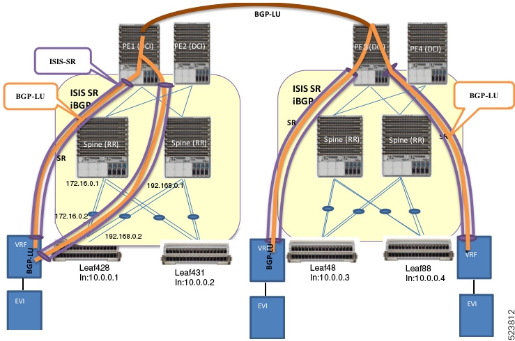
The key components involved in the EVPN bridging and E-Line services over BGP-LU underlay process are:

  • Leaf nodes: Configure EVPN with bridging and inter-subnet routing; act as default gateways for local hosts.

  • Spine nodes: Route traffic between leaf nodes and serve as route reflectors (RR) for iBGP.

  • Provider edge (PE) device and Data Center Interconnect (DCI): Connect spine nodes across data centers.

  • IS-IS labeled IGP and iBGP: Provide internal routing and route reflection across leaf, spine, and DCI nodes.

  • BGP Labeled Unicast (BGP-LU): Establishes labeled routes tunneled through IS-IS Segment Routing (SR) paths between data centers.

EVPN bridging and E-Line services over BGP-LU underlay use leaf and spine nodes with IS-IS and iBGP routing to establish labeled tunnels across data centers. This setup ensures scalable, resilient bridging and routing with efficient load balancing across interconnected sites.

Workflow

These are the stages of EVPN bridging and E-Line services over BGP-LU underlay.

  1. Configure EVPN with bridging and inter-subnet routing on leaf nodes.
  2. Connect hosts to leaf nodes, which route traffic across spine nodes.
  3. Connect spine nodes through PE devices and DCI for inter-data center connectivity.
  4. Enable IS-IS labeled IGP and iBGP across leaf, spine, and DCI nodes, with spine nodes acting as route reflectors.
  5. Configure IS-IS SR policy across leaf, spine, and DCI nodes.
  6. Establish BGP-LU sessions between data centers.
  7. Learn BGP-LU routes on leaf nodes and tunnel them through IS-IS SR labeled paths. For example, leaf node Leaf428 learns BGP-LU routes for remote loopback addresses 10.0.0.3 and 10.0.0.4.

Result

This process enables scalable and resilient EVPN bridging and E-Line services with efficient load balancing and routing across interconnected data centers.

Configure EVPN bridging and E-Line services over BGP-LU underlay with LDP

Configure EVPN Bridging and E-Line Services overging and E-Line Services over a BGP-LU underlay network using LDP.

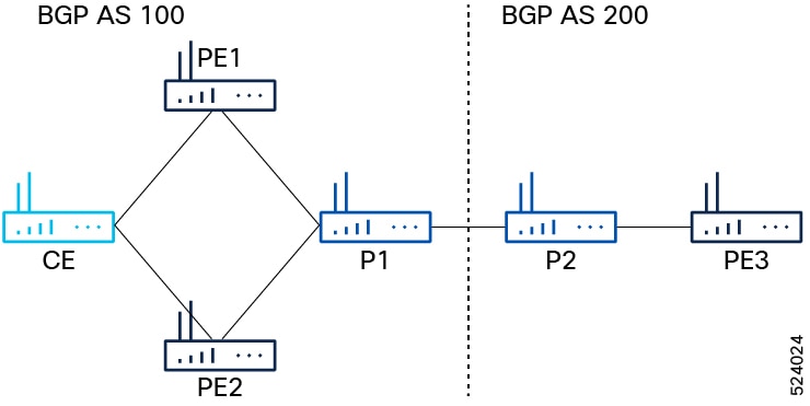
This task applies to a network topology with P routers (P1, P2) and PE routers (PE1, PE2, PE3) connected across two BGP autonomous systems (AS 100 and AS 200). P1 connects to P2, and P1 connects to PE1 and PE2 in AS 100, while P2 connects to PE3 in AS 200.

Before you begin

Ensure you have the network topology as described and access to configure IGP, MPLS, and BGP on all routers.

Procedure


Step 1

Configure IGP, MPLS, and BGP on PE1, PE2, and PE3.

  1. Configure IGP on PE1 and PE2

    Example:

    Router(config)#router ospf pyats_test
    Router(config-ospf)#router-id 54.54.54.54
    Router(config-ospf)#redistribute bgp 100
    Router(config-ospf)#mpls ldp sync
    Router(config-ospf)#mpls ldp auto-config
    Router(config-ospf)#area 0
    Router(config-ospf-ar)#interface loopback0
    Router(config-ospf-ar-if)#exit
    Router(config-ospf-ar)#interface FourHundredGigE0/0/0/2
    Router(config-ospf-ar-if)#commit
    
  2. Configure MPLS on PE1 and PE2.

    Example:

    Router(config)# mpls ldp
    Router(config-ldp)# router-id 54.54.54.54
    Router(config-ldp)# address-family ipv4
    Router(config-ldp-af)# label
    Router(config-ldp-af-lbl)# local
    Router(config-ldp-af-lbl)# allocate for host-routes
    Router(config-ldp-af-lbl-lcl)# root
    Router(config)# mpls ldp
    Router(config-ldp)# interface FourHundredGigE0/0/0/2
  3. Configure BGP on PE1 and PE2.

    Example:

    Router(config)#router bgp 100
    Router(config-bgp)#bgp router-id 54.54.54.54
    Router(config-bgp)#address-family ipv4 unicast
    Router(config-bgp-af)#exit
    Router(config-bgp)#address-family l2vpn evpn 
    Router(config-bgp-af)#retain route-target all
    Router(config-bgp-af)#exit
    Router(config-bgp)#neighbor-group IBGP-PEERS
    Router(config-bgp-nbrgrp)#remote-as 100
    Router(config-bgp-nbrgrp)#update-source loopback0
    Router(config-bgp-nbrgrp)#address-family ipv4 unicast
    Router(config-bgp-nbrgrp-af)#exit
    Router(config-bgp-nbrgrp)#address-family l2vpn evpn
  4. Configure IGP, MPLS, and BGP on PE3.

    Example:

    Router# configure
    Router(config)#router ospf pyats_test
    Router(config-ospf)#router-id 51.51.51.51
    Router(config-ospf)#redistribute bgp 200
    Router(config-ospf)#mpls ldp sync
    Router(config-ospf)#mpls ldp auto-config
    Router(config-ospf)#area 0
    Router(config-ospf-ar)#interface loopback0
    Router(config-ospf-ar-if)#exit
    Router(config-ospf-ar)#interface FourHundredGigE0/0/0/10
    Router(config-ospf-ar-if)#commit
    Router(config)# mpls ldp
    Router(config-ldp)# router-id 51.51.51.51
    Router(config-ldp)# address-family ipv4
    Router(config-ldp-af)# label
    Router(config-ldp-af-lbl)# local
    Router(config-ldp-af-lbl-lcl)# allocate for host-routes
    Router(config-ldp-af-lbl-lcl)# root
    Router(config)# mpls ldp
    Router(config-ldp)# interface FourHundredGigE0/0/0/10
    Router(config-ldp-if)# root
    Router(config)#router bgp 100
    Router(config-bgp)#bgp router-id 54.54.54.54
    Router(config-bgp)#address-family ipv4 unicast
    Router(config-bgp-af)#exit
    Router(config-bgp)#address-family l2vpn evpn 
    Router(config-bgp-af)#retain route-target all
    Router(config-bgp-af)#exit
    Router(config-bgp)# neighbor 56.56.56.56
    Router(config-bgp-nbr)#remote-as 200
    Router(config-bgp-nbr)#update-source loopback0
    Router(config-bgp-nbr)#address-family ipv4 unicast
    Router(config-bgp-nbr-af)#exit
    Router(config-bgp-nbr)#address-family l2vpn evpn

Step 2

Configure iBGP peer on P1 and PE2.

  1. Configure iBGP peer on P1.

    Example:

    Router(config-bgp)# neighbor 52.52.52.52
    Router(config-bgp-nbr)# use neighbor-group IBGP-PEERS
  2. Configure iBGP peer on PE2.

    Example:

    Router(config-bgp)# neighbor 55.55.55.55 
    Router(config-bgp-nbr)# remote-as 100
    Router(config-bgp-nbr)# use neighbor-group IBGP-PEERS
    Router(config-bgp-nbr)# update-source Loopback0
    Router(config-bgp-nbr)# address-family l2vpn evpn

Step 3

Configure P2 as route reflector.

Example:

Router(config)# prefix-set LOOPBACKS
Router(config-pfx)# 53.53.53.53,
Router(config-pfx)# 54.54.54.54,
Router(config-pfx)# 55.55.55.55,
Router(config-pfx)# 52.52.52.52,
Router(config-pfx)# 56.56.56.56,
Router(config-pfx)# 51.51.51.51
Router(config-pfx)# end-set
Router(config)# route-policy passall
Router(config-rpl)# pass
Router(config-rpl)# end-policy
Router(config)# route-policy MATCH_LOOPBACKS
Router(config-rpl)#if destination in LOOPBACKS then
Router(config-rpl-if)#pass
Router(config-rpl-if)#else
Router(config-rpl-else)#drop
Router(config-rpl-else)#endif
Router(config-rpl)#end-policy

Step 4

Configure route policy, IGP, MPLS, and BGP on P1 and P2.

  1. Configure route policy, IGP, MPLS, and BGP on P1.

    Example:

    
    Router(config)#router ospf pyats_test
    Router(config-ospf)#router-id 52.52.52.52
    Router(config-ospf)#redistribute bgp 100
    Router(config-ospf)#mpls ldp sync
    Router(config-ospf)#mpls ldp auto-config
    Router(config-ospf)#area 0
    Router(config-ospf-ar)#interface loopback0
    Router(config-ospf-ar-if)#exit
    Router(config-ospf-ar)#interface FourHundredGigE0/0/0/11
    Router(config-ospf-ar-if)#exit
    Router(config-ospf-ar)#interface FourHundredGigE0/0/0/12 
    Router(config-ospf-ar-if)#root
    Router(config)# router static
    Router(config-static)# address-family ipv4 unicast
    Router(config-static-afi)# 100.0.0.2/32 FourHundredGigE0/0/0/13
    Router(config-static-afi-if)# root
    Router(config)# mpls ldp
    Router(config-ldp)# router-id 52.52.52
    Router(config-ldp)# address-family ipv4
    Router(config-ldp-af)# label
    Router(config-ldp-af-lbl)# local
    Router(config-ldp-af-lbl-lcl)# allocate for host-routes
    Router(config-ldp-af-lbl-lcl)# root
    Router(config)# mpls ldp
    Router(config-ldp)# interface FourHundredGigE0/0/0/11
    Router(config-ldp-if)# exit
    Router(config-ldp)# interface FourHundredGigE0/0/0/12
  2. Configure route policy, IGP, MPLS, and BGP on P2.

    Example:

    Router(config)#router ospf pyats_test
    Router(config-ospf)#router-id 56.56.56.56
    Router(config-ospf)#redistribute bgp 200
    Router(config-ospf)#mpls ldp sync
    Router(config-ospf)#mpls ldp auto-config
    Router(config-ospf)#area 0
    Router(config-ospf-ar)#interface loopback0
    Router(config-ospf-ar-if)#passive enable
    Router(config-ospf-ar-if)#exit
    Router(config-ospf-ar)#interface FourHundredGigE0/0/0/2
    Router(config-ospf-ar)#root
    Router(config)# router static
    Router(config-static)# address-family ipv4 unicast
    Router(config-static-afi)# 100.0.0.1/32 FourHundredGigE0/0/0/5
    Router(config-static-afi)# root
    Router(config)# mpls ldp
    Router(config-ldp)# router-id 56.56.56.56
    Router(config-ldp)# address-family ipv4
    Router(config-ldp-af)# label
    Router(config-ldp-af-lbl)# local
    Router(config-ldp-af-lbl-lcl)# allocate for host-routes
    Router(config-ldp-af-lbl-lcl)# root
    Router(config)# mpls ldp
    Router(config-ldp)# interface FourHundredGigE0/0/0/4
  3. Configure router reflector client on P2, which is essential for copying the EVPN routes between the AS.

    Example:

    
    Router(config)#router bgp 200
    Router(config-bgp)#bgp router-id 56.56.56.56
    Router(config-bgp)#address-family ipv4 unicast
    Router(config-bgp-af)#network 51.51.51.51/32
    Router(config-bgp-af)#network 52.52.52.52/32
    Router(config-bgp-af)#network 53.53.53.53/32
    Router(config-bgp-af)#network 54.54.54.54/32
    Router(config-bgp-af)#network 55.55.55.55/32
    Router(config-bgp-af)#network 56.56.56.56/32
    Router(config-bgp-af)#redistribute connected
    Router(config-bgp-af)#redistribute ospf 0
    Router(config-bgp-af)#allocate-label all
    Router(config-bgp-af)#exit
    Router(config-bgp)#address-family l2vpn evpn 
    Router(config-bgp-af)#retain route-target all
    Router(config-bgp-af)#exit
    Router(config-bgp)#neighbor-group IBGP-PEERS
    Router(config-bgp-nbrgrp)#remote-as 200
    Router(config-bgp-nbr)#update-source loopback0
    Router(config-bgp-nbr)#address-family ipv4 unicast
    Router(config-bgp-nbr-af)#exit
    Router(config-bgp-nbr)#address-family l2vpn evpn
    Router(config-bgp-nbr-af)#route-reflector-client

Step 5

Configure P1 and P2 as eBGP neighbor.

  1. Configure P1 as eBGP neighbor.

    Example:

    Router(config-bgp)# neighbor 100.0.0.1
    Router(config-bgp-nbr)#remote-as 100
    Router(config-bgp-nbr)#ebgp-multihop 255
    Router(config-bgp-nbr)#address-family ipv4 labeled-unicast 
    Router(config-bgp-nbr-af)#next-hop-self 
    Router(config-bgp-nbr-af)#route-policy passall in
    Router(config-bgp-nbr-af)#route-policy MATCH_LOOPBACKS out
    Router(config-bgp-nbr-af)#send-extended-community-ebgp 
    Router(config-bgp-nbr-af)#exit
    Router(config-bgp-nbr)#address-family l2vpn evpn
    Router(config-bgp-nbr-af)#route-policy passall in
    Router(config-bgp-nbr-af)#route-policy passall out
    Router(config-bgp-nbr-af)#next-hop-unchanged
  2. Configure P2 as eBGP neighbor.

    Example:

    Router(config-bgp)# neighbor 100.0.0.2
    Router(config-bgp-nbr)#remote-as 200
    Router(config-bgp-nbr)#ebgp-multihop 255
    Router(config-bgp-nbr)#address-family ipv4 labeled-unicast 
    Router(config-bgp-nbr-af)#next-hop-self 
    Router(config-bgp-nbr-af)#route-policy passall in
    Router(config-bgp-nbr-af)#route-policy MATCH_LOOPBACKS out
    Router(config-bgp-nbr-af)#send-extended-community-ebgp 
    Router(config-bgp-nbr-af)#exit
    Router(config-bgp-nbr)#address-family l2vpn evpn
    Router(config-bgp-nbr-af)#route-policy passall in
    Router(config-bgp-nbr-af)#route-policy passall out
    Router(config-bgp-nbr-af)#next-hop-unchanged

Step 6

Configure PE1, PE2, and PE3 as iBGP neighbor.

  1. Configure PE3 as iBGP neighbor.

    Example:

    Router(config-bgp)#neighbor 51.51.51.51 
    Router(config-bgp-nbr)#use neighbor-group IBGP-PEERS
  2. Configure PE1 and PE2 as iBGP neighbor.

    Example:

    
    Router(config-bgp)#neighbor 54.54.54.54 
    Router(config-bgp-nbr)#use neighbor-group IBGP-PEERS
    Router(config-bgp-nbr)#exit
    Router(config-bgp)#neighbor 55.55.55.55 
    Router(config-bgp-nbr)#use neighbor-group IBGP-PEERS

Step 7

For P1, the iBGP peers are PE1 and PE2, and the eBGP peer is P2.

  1. For P1, the iBGP peers are PE1 and PE2, and the eBGP peer is P2.

    Example:

    Router(config)# prefix-set LOOPBACKS
    Router(config-pfx)# 53.53.53.53,
    Router(config-pfx)# 54.54.54.54,
    Router(config-pfx)# 55.55.55.55,
    Router(config-pfx)# 52.52.52.52,
    Router(config-pfx)# 56.56.56.56,
    Router(config-pfx)# 51.51.51.51
    Router(config-pfx)# end-set
    Router(config)# route-policy passall
    Router(config-rpl)# pass
    Router(config-rpl)# end-policy
    Router(config)# route-policy MATCH_LOOPBACKS
    Router(config-rpl)#if destination in LOOPBACKS then
    Router(config-rpl-if)#pass
    Router(config-rpl-if)#else
    Router(config-rpl-else)#drop
    Router(config-rpl-else)#endif
    Router(config-rpl)#end-policy
    
  2. Configure router reflector client.

    Example:

    
    Router(config)#router bgp 100
    Router(config-bgp)#bgp router-id 52.52.52.52
    Router(config-bgp)#address-family ipv4 unicast
    Router(config-bgp-af)#network 51.51.51.51/32
    Router(config-bgp-af)#network 52.52.52.52/32
    Router(config-bgp-af)#network 53.53.53.53/32
    Router(config-bgp-af)#network 54.54.54.54/32
    Router(config-bgp-af)#network 55.55.55.55/32
    Router(config-bgp-af)#network 56.56.56.56/32
    Router(config-bgp-af)#redistribute connected
    Router(config-bgp-af)#redistribute ospf 0
    Router(config-bgp-af)#allocate-label all
    Router(config-bgp-af)#exit
    Router(config-bgp)#address-family l2vpn evpn 
    Router(config-bgp-af)#retain route-target all
    Router(config-bgp-af)#exit
    Router(config-bgp)#neighbor-group IBGP-PEERS
    Router(config-bgp-nbrgrp)#remote-as 100
    Router(config-bgp-nbr)#update-source loopback0
    Router(config-bgp-nbr)#address-family ipv4 unicast
    Router(config-bgp-nbr-af)#exit
    Router(config-bgp-nbr)#address-family l2vpn evpn
    Router(config-bgp-nbr-af)#route-reflector-client

Step 8

Configure L2VPN and EVPN on PE1, PE2, and PE3.

Example:

Router(config)# l2vpn 
Router(config-l2vpn)# bridge group bg1
Router(config-l2vpn-bg)# bridge-domain bd1
Router(config-l2vpn-bg-bd)# interface Bundle-Ether3.1
Router(config-l2vpn-bg-bd-ac)# evi 1
Router(config-l2vpn-bg-bd-ac)# root
Router(config)# l2vpn 
Router(config-l2vpn)# bridge group bg2
Router(config-l2vpn-bg)# bridge-domain bd2
Router(config-l2vpn-bg-bd)# interface Bundle-Ether3.2
Router(config-l2vpn-bg-bd-ac)# evi 2
Router(config-l2vpn-bg-bd-ac-evi)# root
Router(config)# evpn
Router(config-evpn)# evi 1
Router(config-evpn-evi)# advertise-mac
Router(config-evpn-evi)# exit
Router(config-evpn)# evi 2
Router(config-evpn-evi)# advertise-mac

Step 9

Use these show commands to verify that you have successfully configured EVPN bridging and E-Line services over BGP-LU underlay with LDP.

  • show evpn internal-label vpn-id 1 detail

  • show bgp l2vpn evpn route-type inclusive-mcast

  • show l2vpn forwarding bridge-domain mac location 0/RP0/CPU0

  • show bgp l2vpn evpn route-type mac-advertisement

Example:

Router# show evpn internal-label vpn-id 1 detail

VPN-ID     Encap  Ethernet Segment Id         EtherTag     Label   
---------- ------ --------------------------- ----------   --------
1          MPLS   0040.0000.0000.0000.0001    0            24010   
   Multi-paths resolved: TRUE (Remote all-active) 
   Multi-paths Internal label: 24010
    EAD/ES  (ID:0x0000000000000652)
                54.54.54.54                                0              
                55.55.55.55                                0              
    EAD/EVI (ID:0x0000000000000649)
                54.54.54.54                                24000          
                55.55.55.55                                24000          
   Summary pathlist (ID 0x000000000000064d):
 0x02000001 (P) 54.54.54.54                                24000          
 0x02000002 (P) 55.55.55.55                                24000          
Router# show bgp l2vpn evpn route-type inclusive-mcast

BGP router identifier 51.51.51.51, local AS number 200
BGP generic scan interval 60 secs
Non-stop routing is enabled
BGP table state: Active
Table ID: 0x0
BGP table nexthop route policy: 
BGP main routing table version 100
BGP NSR Initial initsync version 1 (Reached)
BGP NSR/ISSU Sync-Group versions 0/0
BGP scan interval 60 secs

Status codes: s suppressed, d damped, h history, * valid, > best
              i - internal, r RIB-failure, S stale, N Nexthop-discard
Origin codes: i - IGP, e - EGP, ? - incomplete
   Network            Next Hop            Metric LocPrf Weight Path
Route Distinguisher: 51.51.51.51:1 (default for vrf bd1)
Route Distinguisher Version: 94
*> [3][0][32][51.51.51.51]/80
                      0.0.0.0                                0 i N
*>i[3][0][32][54.54.54.54]/80
                      54.54.54.54                   100      0 100 i N
*>i[3][0][32][55.55.55.55]/80
                      55.55.55.55                   100      0 100 i N
Route Distinguisher: 51.51.51.51:2 (default for vrf bd2)
Route Distinguisher Version: 100
*> [3][0][32][51.51.51.51]/80
                      0.0.0.0                                0 i N
*>i[3][0][32][54.54.54.54]/80
                      54.54.54.54                   100      0 100 i N
*>i[3][0][32][55.55.55.55]/80
                      55.55.55.55                   100      0 100 i N
Route Distinguisher: 54.54.54.54:1
Route Distinguisher Version: 92
*>i[3][0][32][54.54.54.54]/80
                      54.54.54.54                   100      0 100 i N
Route Distinguisher: 54.54.54.54:2
Route Distinguisher Version: 99
*>i[3][0][32][54.54.54.54]/80
                      54.54.54.54                   100      0 100 i N
Route Distinguisher: 55.55.55.55:1
Route Distinguisher Version: 67
*>i[3][0][32][55.55.55.55]/80
                      55.55.55.55                   100      0 100 i N
Route Distinguisher: 55.55.55.55:2
Route Distinguisher Version: 96
*>i[3][0][32][55.55.55.55]/80
                      55.55.55.55                   100      0 100 i N

Processed 10 prefixes, 10 paths
Router# show l2vpn forwarding bridge-domain mac location 0/RP0/CPU0

 To Resynchronize MAC table from the Network Processors, use the command...
    l2vpn resynchronize forwarding mac-address-table location <r/s/i>

Mac Address    Type    Learned from/Filtered on    LC learned Resync Age/Last Change Mapped to       
-------------- ------- --------------------------- ---------- ---------------------- --------------  
0000.cccc.dddd dynamic FH0/0/0/0.2                 N/A        12 Mar 13:17:36        N/A   --> MAC 0000.cccc.dddd was locally learned from interface FH0/0/0/0.2         
0000.aaaa.bbbb EVPN    BD id: 1                    N/A        N/A                    N/A   --> MAC 0000.aaaa.bbbb was advertised from PE1/PE2
Router# show bgp l2vpn evpn route-type mac-advertisement

BGP router identifier 51.51.51.51, local AS number 200
BGP generic scan interval 60 secs
Non-stop routing is enabled
BGP table state: Active
Table ID: 0x0
BGP table nexthop route policy: 
BGP main routing table version 100
BGP NSR Initial initsync version 1 (Reached)
BGP NSR/ISSU Sync-Group versions 0/0
BGP scan interval 60 secs

Status codes: s suppressed, d damped, h history, * valid, > best
              i - internal, r RIB-failure, S stale, N Nexthop-discard
Origin codes: i - IGP, e - EGP, ? - incomplete
   Network            Next Hop            Metric LocPrf Weight Path
Route Distinguisher: 51.51.51.51:2 (default for vrf bd2)
Route Distinguisher Version: 100
*>i[2][0][48][0000.aaaa.bbbb][0]/104 --> 
                      54.54.54.54                   100      0 100 i N
* i                   55.55.55.55                   100      0 100 i N
*> [2][0][48][0000.cccc.dddd][0]/104 --> 
                      0.0.0.0                                0 i N
Route Distinguisher: 54.54.54.54:2
Route Distinguisher Version: 99
*>i[2][0][48][0000.aaaa.bbbb][0]/104
                      54.54.54.54                   100      0 100 i N
Route Distinguisher: 55.55.55.55:2
Route Distinguisher Version: 96
*>i[2][0][48][0000.aaaa.bbbb][0]/104
                      55.55.55.55                   100      0 100 i N
Processed 4 prefixes, 5 paths

Configure EVPN bridging and E-Line services over BGP-LU underlay with SR

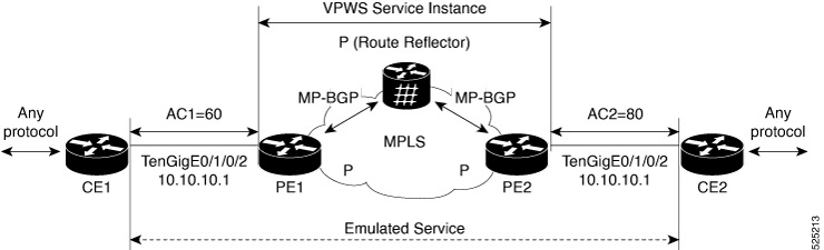
Configure EVPN bridging and E-Line services over a BGP-LU underlay network using SR for efficient traffic engineering and simplified forwarding.

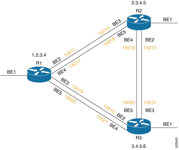
This task applies to networks where Segment Routing is enabled within the IGP domain using IS-IS, and BGP-LU is used to advertise loopback addresses with associated SR labels. The configuration involves PE and Route Reflector (RR) nodes participating in EVPN services over the SR-enabled underlay.

Before you begin

Ensure all participating nodes support IS-IS with Segment Routing and BGP-LU. Have loopback interfaces configured for router IDs and SR prefix SIDs assigned.

Procedure


Step 1

Configure IS-IS with SR on all participating nodes.

Configure SR with IS-IS to enable SR within the IGP domain and assign prefix SIDs to the router loopback interface. Configure all the participating nodes, which include the PE or Route Reflector (RR) nodes in the underlay to run IS-IS and advertise their loopbacks with SIDs. The prefix SID varies for each node and instance.

Example:

Router#config
Router(config)#router isis igp1
Router(config-isis)#address-family ipv4 unicast 
Router(config-isis-af)#segment-routing mpls sr-prefer 
Router(config-isis-af)#segment-routing prefix-sid-map advertise-local
Router(config-isis-af)#exit
Router(config-isis)#address-family ipv6 unicast 
Router(config-isis-af)#segment-routing mpls sr-prefer 
Router(config-isis-af)#segment-routing prefix-sid-map advertise-local
Router(config-isis-af)#exit
Router(config-isis)#interface Loopback 0
Router(config-isis-if)#passive 
Router(config-isis-if)#address-family ipv4 unicast 
Router(config-isis-if-af)#prefix-sid index 1 
Router(config-isis-if-af)#exit
Router(config-isis-if)#address-family ipv6 unicast 
Router(config-isis-if-af)#prefix-sid index 101

Step 2

Configure BGP on all nodes.

Ensure that the bgp router-id is the loopback address used for peering and SR SID assignment. The router ID varies for each node.

Example:

Router(config)#router bgp 65600
Router(config-bgp)#nsr
Router(config-bgp)#bgp router-id 192.168.1.1
Router(config-bgp)#bgp graceful-restart 
Router(config-bgp)#ibgp policy out enforce-modifications

Step 3

Enable the BGP-LU address families and advertise the router loopback address with an associated label derived from the SR node SID.

Configure all the participating nodes to advertise the router loopback address through BGP-LU.

Example:

The network and SID index vary for each node. The following is a sample configuration for IPv4 and IPv6 unicast address families.

Router#config
Router(config)#router bgp 64600
Router(config-bgp)#address-family ipv4 unicast 
Router(config-bgp-af)#additional-paths receive 
Router(config-bgp-af)#additional-paths send
Router(config-bgp-af)#nexthop trigger-delay critical 50
Router(config-bgp-af)#network 192.168.1.1/32 route-policy SID (1)
Router(config-bgp-af)#allocate-label all
Router(config-bgp-af)#exit             
Router(config-bgp)#address-family ipv6 unicast 
Router(config-bgp-af)#additional-paths receive 
Router(config-bgp-af)#additional-paths send 
Router(config-bgp-af)#nexthop trigger-delay critical 50
Router(config-bgp-af)#network 2001:DB8::/32 route-policy SID (101)
Router(config-bgp-af)#allocate-label all

Example:

Sample route-policy configuration.

Router#config
Router(config)#route-policy SID ($SID)
Router(config-rpl)#set label-index $SID
Router(config-rpl)#end-policy 

Step 4

Configure BGP neighbors and neighbor groups.

Configure the BGP neighbors or neighbor groups to establish iBGP peering between all the participating nodes such as PEs and RRs, and enable the BGP-LU and EVPN address families.

  1. Create a session group with remote AS and update source as loopback0.

    Example:

    Router(config)#router bgp 64600 
    Router(config-bgp)#session-group current
    Router(config-bgp-sngrp)#remote-as 64600
    Router(config-bgp-sngrp)#update-source Loopback 0
  2. Configure a BGP neighbor group for BGP-LU for IPv4 and IPv6 address families.

    Example:

    
    Router(config-bgp)#neighbor-group bgp-lu-rr
    Router(config-bgp-nbrgrp)#use session-group current
    Router(config-bgp-nbrgrp)#address-family ipv4 labeled-unicast 
    Router(config-bgp-nbrgrp-af)#next-hop-self 
    Router(config-bgp-nbrgrp-af)#exit
    Router(config-bgp-nbrgrp)#address-family ipv6 labeled-unicast 
    Router(config-bgp-nbrgrp-af)#next-hop-self 
    Router(config-bgp-nbrgrp-af)#exit
  3. Configure BGP neighbor group for L2VPN services such as VPLS-VPWS and EVPN address families.

    Example:

    Router(config-bgp)#neighbor-group bgp-lu-rr
    Router(config-bgp-nbrgrp)#use session-group current
    Router(config-bgp-nbrgrp)#address-family ipv4 labeled-unicast 
    Router(config-bgp-nbrgrp-af)#next-hop-self 
    Router(config-bgp-nbrgrp-af)#exit
    Router(config-bgp-nbrgrp)#address-family ipv6 labeled-unicast
    Router(config-bgp-nbrgrp)#address-family l2vpn vpls-vpws 
    Router(config-bgp-nbrgrp-af)#exit
    Router(config-bgp-nbrgrp)#address-family l2vpn evpn
  4. Associate an individual BGP neighbor with a predefined neighbor group.

    Example:

    Router(config)#router bgp 64600
    Router(config-bgp)#neighbor 192.168.101.1 
    Router(config-bgp-nbr)#use neighbor-group bgp-lu-rr
    Router(config-bgp-nbr)#commit

L2VPN services over segment routing traffic engineering tunnel

Segment routing is a source routing technology that

  • enables the source device to select a path and encode it in the packet header as an ordered list of segments

  • uses segments as identifiers for various instructions, and

  • supports traffic engineering by creating tunnels between source and destination pairs where the source specifies the path for the packet to follow.

Segment routing for traffic engineering and preferred tunnel path

Segment routing for traffic engineering (SR-TE) establishes a tunnel between a source and destination pair using source routing. The source calculates the path and encodes it as segments in the packet header. Each segment represents an end-to-end path that directs routers in the provider core network to follow the specified route instead of the shortest path determined by the IGP. The destination remains unaware of the tunnel's existence.

Using segment routing to transport MPLS L2VPN services enhances network resilience and convergence compared to MPLS LDP. Segment routing integrates directly with the MPLS architecture without modifying the forwarding plane. In an MPLS data plane segment-routing network, label distribution is handled by the IGP, eliminating the need for LDP or other signaling protocols. This simplification reduces protocol interactions, making the network more robust and stable. Additionally, segment routing optimizes bandwidth usage and reduces latency compared to traditional MPLS networks.

Preferred tunnel path functionality enables mapping pseudowires to specific traffic-engineering tunnel paths. Attachment circuits connect to designated SR traffic engineering tunnel interfaces rather than remote PE router IP addresses reachable via IGP or LDP. The traffic engineering tunnel then transports traffic from the source to destination PE routers. An SR Policy selects a path when it is valid and has the highest preference value among all candidate paths.

These are the supported services:

  • L2VPN preferred path

  • VPWS over SR-TE policy

  • Decoupled mode for L2VPN and EVPN VPWS services

  • VPWS PW over preferred SR-TE using statically configured SR policy

  • EVPN PW over preferred SR-TE using On-Demand Nexthop SR policy

  • Call admission control for L2VPN point-to-point services over circuit-style SR-TE policies

L2VPN preferred path

L2VPN preferred-path allows you to steer PW traffic over an SR-TE tunnel at the granularity of per PW level. It is recommended to use preferred-path configuration together with statically configured SR policy. EVPN ODN configuration allows you to steer PW traffic over an SR-TE tunnel at the granularity of per EVPN instance (EVI) level. When both the preferred-path and EVPN ODN configurations are used on a PW, preferred-path configuration takes precedence.

VPWS over SR-TE policy

A virtual private wire service (VPWS) is a Layer 2 VPN service that

  • connects two locations through a PW

  • encapsulates PW traffic within an MPLS label stack used for routing, and

  • uses SR-TE policies to control the path the PW takes through the network instead of relying on Label Distribution Protocol (LDP).

For more information on SR-TE policy, see the Configure SR-TE Policies section in the Segment Routing Configuration Guide for Cisco 8000 Series Routers, IOS XR.

Table 2. Feature History Table

Feature Name

Release Information

Feature Description

VPWS over SR-TE policy

Release 24.4.1

Introduced in this release on: Fixed Systems (8700) (select variants only*)

* The VPWS over SR-TE policy functionality is now extended to the Cisco 8712-MOD-M routers.

VPWS over SR-TE policy

Release 24.3.1

Introduced in this release on: Fixed Systems (8200, 8700); Modular Systems (8800 [LC ASIC: P100]) (select variants only*)

* The VPWS over SR-TE policy functionality is now extended to:

  • 8212-48FH-M

  • 8711-32FH-M

  • 88-LC1-52Y8H-EM

  • 88-LC1-12TH24FH-E

VPWS over SR-TE policy

Release 24.2.11

Introduced in this release on: Modular Systems (8800 [LC ASIC: P100]) (select variants only*)

* The VPWS over SR-TE policy functionality is now extended to routers with the 88-LC1-36EH line cards.

VPWS over SR-TE policy

Release 7.7.1

Using the SR-TE policy, you can now set the preferred path between two endpoints for Virtual Private Wire Service (VPWS). This gives you the advantage of a reduced number of dedicated networks to provision IP and VPN services across SR-TE tunnels.

The VPWS is a method to provide Ethernet-based point to point communication over MPLS or IP networks.

VPWS preferred path using SR-TE policy

Using SR-TE policies, you can set a preferred path between two endpoints for VPWS. This approach reduces the need to provision multiple dedicated networks for IP and VPN services across SR-TE tunnels, simplifying network management and improving efficiency.

VPWS provides Ethernet-based point-to-point communication over MPLS or IP networks. Cisco 8000 series routers support VPWS implementation through these methods:

  • EVPN VPWS

  • LDP VPWS

  • EVPN VPWS On-Demand Nexthop

How segment routing traffic engineering steers pseudowire traffic

Summary

The key components involved in the process are:

  • Pseudowire (PW): A virtual point-to-point connection between routers that carries encapsulated traffic.

  • Routers R1, R2, and R3: Network devices where R1 and R3 are endpoints of the PW, and R2 is an intermediate router.

  • Segment Routing Traffic Engineering (SR-TE) policy: A routing policy that defines a preferred path for traffic steering.

SR-TE steers pseudowire traffic by enforcing a preferred path through an intermediate router instead of the default direct route. This approach improves network resource utilization and traffic control.

Workflow

These stages describe how SR-TE steers pseudowire traffic.

  1. By default, the PW between routers R1 and R3 takes the direct path from R1 to R3.
  2. You configure an SR-TE policy with a preferred path that specifies traffic should be steered through router R2.
  3. The SR-TE policy enforces the traffic to follow the defined path, steering the PW traffic from R1 to R3 via R2 instead of the direct route.

Result

This process enables controlled traffic engineering by steering pseudowire traffic along a preferred path, improving network resource utilization and traffic management.

Decoupled mode for L2VPN and EVPN VPWS services

Decoupled mode is a network capability in L2VPN and EVPN VPWS that

  • improves network reliability and resilience

  • enables PW to function independently from the AC, maintaining PW traffic continuity despite AC failure, and

  • employs the xconnect, a virtual connection that links the AC and PW segments, to efficiently manage state transitions.

Table 3. Feature History Table

Feature Name

Release Information

Feature Description

Decoupled mode for L2VPN and EVPN VPWS services

Release 25.2.1

Introduced in this release on: Fixed Systems (8200, 8700); Centralized Systems (8600); Modular Systems (8800 [LC ASIC: Q100, Q200, P100, K100])

Decoupled mode improves fault tolerance by allowing the PE router to maintain the PW in an active state independently of the AC status. Unlike the traditional coupled mode, which requires both AC and PW to be active for traffic flow, decoupled mode ensures uninterrupted PW traffic even during AC failures.

The feature introduces these changes:

CLI:

YANG Data Model:

  • Cisco-IOS-XR-l2vpn-cfg.yang

  • Cisco-IOS-XR-l2vpn-oper.yang

(see GitHub, YANG Data Models Navigator)

Decoupled mode states

Decoupled mode uses the XTC to manage traffic flow dynamically by transitioning between states based on the operational status of the AC and PW:

  • Bound state: Both AC and PW segments are operational. The XC is bound, allowing traffic to flow seamlessly between the AC and PW segments.

  • Unbound state: Either the AC or PW segment fails. The XC enters an unbound state and drops any pending data on the AC. If the AC fails, the PE router brings down the PW connection, stopping traffic flow or rerouting it through alternative paths. If the PW fails, the XC brings down the AC connection and stops traffic flow.

  • Bound down state: When the AC segment fails, the XC keeps the PW active, maintaining PW traffic flow between PE routers. If the PW segment fails, the XC enters an unbound state, brings down the AC segment, and stops traffic flow.

Before Release 25.2.1, the default configuration for VPWS was the coupled mode, which supported only bound and unbound XC states. For more information, see the VPWS over SR-TE policy.

From Release 25.2.1, you can configure the decoupled mode in addition to the existing coupled mode. Decoupled mode allows PW traffic to continue forwarding even when the AC experiences a failure, enhancing service resilience.

Limitations for decoupled mode

The router does not support decoupled mode for these configurations:

  • PWHE AC segment

  • Multi-segment PW

  • Local switching between AC

  • BGP auto-discovery for PW

  • Multihoming EVPN circuits

How decoupled mode works

Summary

The key components involved in the process are:

  • Customer edge device (CE1 and CE2): End devices connected to the provider network.

  • Provider edge router (PE1 and PE2): Network devices managing PW and AC connections.

  • Route reflector: Facilitates routing information exchange between PE1 and PE2.

Decoupled Mode improves network resilience by enabling PE routers to independently manage PW and AC connections. This separation ensures continuous PW traffic and dynamic fault management between CE devices and PE routers.

Workflow

These stages describe how the decoupled mode works.

The stages described here are not sequential. They illustrate different aspects of how the decoupled mode works, and may occur independently or in varying order depending on the scenario.

  1. Scenario 1: Both AC and PW are active
    • CE1 sends a packet to PE1 via the active AC.
    • PE1 looks up the packet destination and forwards it over the active PW to PE2.
    • PE1 encapsulates and transmits the packet to PE2.
    • PE2 receives the packet, determines the next hop, and forwards it to CE2 via the active AC.
    • CE2 successfully receives the packet.
  2. Scenario 2: AC experiences a failure
    • CE1 sends a packet to PE1.
    • PE1 detects the AC failure but keeps the PW operational without signaling it inactive.
    • The cross-connect (XC) transitions to a bound-down state, allowing PW traffic to continue.
    • PE1 forwards the packet over the active PW to PE2.
    • PE2 forwards the packet to CE2 via the active AC.
    • CE2 successfully receives the packet.
  3. Scenario 3: PW experiences a failure
    • CE1 sends a packet to PE1 via the active AC.
    • PE1 detects the PW failure and signals the AC to become inactive.
    • The route reflector updates PE2 about the AC state change.
    • PE2 blocks traffic from CE2, and PE1 blocks traffic from CE1.
    • The XC drops any pending data on the AC, stopping all traffic flow.

Result

This process ensures network resilience by maintaining PW traffic independently of AC status, allowing dynamic fault handling and uninterrupted communication between CE devices through PE routers.

Configure decoupled mode for L2VPN and EVPN VPWS services

Enable decoupled mode on PE routers to maintain PW activity even if the AC fails, ensuring continuous Layer 2 VPN service.

Decoupled mode allows a point-to-point pseudowire service to extend a Layer 2 network over a Layer 3 IP and MPLS infrastructure, improving service resilience.

Procedure

Step 1

Enable L2VPN services and create a point-to-point pseudowire service.

Enable L2VPN services and configure a p2p pseudowire service that extends a Layer 2 network across a Layer 3 IP and MPLS network.

Example:
Router# configuration
Router(config)# l2vpn
Router(config-l2vpn)# xconnect group g1
Router(config-l2vpn-xc)# p2p xc1

Step 2

Enable decoupled mode on the point-to-point pseudowire service.

Enable decoupled mode within p2p services, which keeps the PW active even if the AC experiences a failure.

Example:
Router(config-l2vpn-xc-p2p)# decoupled-mode

Step 3

Configure the interface and establish the pseudowire with the appropriate neighbor and service ID.

Enable interface and configure PW, ipv4 , EVPN or MPLS services for establishing the required L2VPN service over a network.

Example:
Router(config-l2vpn-xc-p2p)# interface TenGigE0/1/0/2
Router(config-l2vpn-xc-p2p)# neighbor evpn evi 1 service-id 10011
Router(config-l2vpn-xc-p2p)# commit

Step 4

Use the show l2vpn command to verify the XC, AC, and PW states.

Example:

In this example, both the AC and PW are in the bound state, and the XC is in the up state.

Router# show l2vpn xconnect group g1 xc-name p1 detail
Group g1, XC p1, state is up; Interworking none 
Decoupled mode: Enabled 
  AC: GigabitEthernet0/0/0/2.1, state is up 
    Type VLAN; Num Ranges: 1
    Rewrite Tags: []
    VLAN ranges: [1, 1]
    MTU 1504; XC ID 0x1; interworking none
    Statistics:
      packets: received 0, sent 0
      bytes: received 0, sent 0
      drops: illegal VLAN 0, illegal length 0
  PW: neighbor 1.1.1.1, PW ID 1, state is up ( established ) 
    PW class not set, XC ID 0xfff80013
    Encapsulation MPLS, protocol LDP
    Source address 2.2.2.2
    PW type Ethernet, control word disabled, interworking none
    PW backup disable delay 0 sec
    Sequencing not set
    Ignore MTU mismatch: Disabled
    Transmit MTU zero: Disabled
    LSP : Up 
    Nexthop type: IPV4 1.1.1.1
Example:

In this example, due to a local AC fault, the AC is in the down state and the PW is in the up state.

Router# show l2vpn xconnect group g1 xc-name p1 detail

Group g1, XC p1, state is down; Interworking none 
Decoupled mode: Enabled 
  AC: GigabitEthernet0/0/0/2.1, state is down (Admin) 
    Type VLAN; Num Ranges: 1
    Rewrite Tags: []
    VLAN ranges: [1, 1]
    MTU 1504; XC ID 0x1; interworking none
    Statistics:
      packets: received 0, sent 0
      bytes: received 0, sent 0
      drops: illegal VLAN 0, illegal length 0
  PW: neighbor 1.1.1.1, PW ID 1, state is up ( established ) 
    PW class not set, XC ID 0xfff80013
    Encapsulation MPLS, protocol LDP
    Source address 2.2.2.2
    PW type Ethernet, control word disabled, interworking none
    PW backup disable delay 0 sec
    Sequencing not set
    Ignore MTU mismatch: Disabled
    Transmit MTU zero: Disabled
    LSP : Up 
    Nexthop type: IPV4 1.1.1.1

Step 5

Use the show l2vpn forwarding xconnect <xc-id> detail location <location> command to verify the xconnect and PW binding state.

Example:

In this example, the XC is in the down state, both AC and PW are in a bound state, and the segment can still carry traffic across the PW despite the AC failure.

Router# show l2vpn forwarding xconnect 0x1 detail location 0/0/CPU0

Local interface: GigabitEthernet0/0/0/2.1, Xconnect id: 0x1, Status: down 
  Segment 1
    AC, GigabitEthernet0/0/0/2.1, status: Bound 
    Statistics:
      packets: received 0, sent 0
      bytes: received 0, sent 0
  Segment 2
    MPLS, Destination address: 1.1.1.1, pw-id: 1, status: Bound 
    Pseudowire label: 24014
    Control word disabled
    Statistics:
      packets: received 0, sent 0
      bytes: received 0, sent 0
    PD System Data:  0x00000000, 0x00000000, 0x00000000, 0x01000000, 0x22000000,
                    0x00000000, 0x00000000
Example:

In this example, the XC is in the up state and both AC and PW are in bound state.

Router# show l2vpn forwarding xconnect 0x1 detail location 0/0/CPU0

Local interface: GigabitEthernet0/0/0/2.1, Xconnect id: 0x1, Status: up 
  Segment 1
    AC, GigabitEthernet0/0/0/2.1, status: Bound 
    Statistics:
      packets: received 0, sent 0
      bytes: received 0, sent 0
  Segment 2
    MPLS, Destination address: 1.1.1.1, pw-id: 1, status: Bound 
    Pseudowire label: 24014
    Control word disabled

VPWS PW over preferred SR-TE using statically configured SR policy

A preferred path configuration is a feature that

  • allows setting the preferred path between two endpoints for EVPN VPWS PW or LDP VPWS PW using a statically configured policy

  • supports both bundle AC and physical AC, and

  • enables control over the forwarding path to optimize network performance and reliability.

Restrictions for VPWS PW over preferred SR-TE using statically configured SR policy

  • EVPN VPWS SR policy is not supported on EVPN VPWS dual homing.

  • EVPN validates if the route is for a single home nexthop, otherwise it issues an error message about a dangling SR TE policy, and continues to set up EVPN-VPWS without it. EVPN relies on ESI value being zero to determine if this is a single home or not. If the AC is a Bundle-Ether interface running LACP then you must manually configure the ESI value to zero to overwrite the auto-sense ESI as EVPN VPWS multihoming is not supported.

    To disable EVPN dual homing, configure bundle-Ether AC with ESI value set to zero.
    
    evpn
    interface Bundle-Ether12
      ethernet-segment
       identifier type 0 00.00.00.00.00.00.00.00.00
    /* Or globally */
    evpn 
     ethernet-segment type 1 auto-generation-disable
    

Configure VPWS pseudowire over preferred SR-TE using statically configured SR policy

Ensure successful configuration of VPWS PW over a preferred SR-TE path using a statically configured SR policy for both EVPN VPWS and LDP VPWS.

This task applies when you want to leverage statically configured SR-TE policies to control the preferred path for VPWS pseudowires in your network, enhancing traffic engineering and path selection.

Before you begin

  • Confirm that IS-IS is running as the IGP.

  • Ensure MPLS and SR features are supported and enabled on your devices.

  • For LDP VPWS, configure MPLS LDP as a baseline for label distribution.

Procedure

Step 1

Configure SR in IS-IS, adjacency-SID, and prefix-SID.

Enable SR in IS-IS and configure adjacency-SID on BE2, BE3, BE4, and BE5.

  1. Enable SR in IS-IS

    Example:
    Router(config)# router isis isp
    Router(config-isis)# net 01.0000.0000.0001.00
    Router(config-isis)# distribute link-state instance-id 32 level 2 throttle 5
    Router(config-isis)# address-family ipv4 unicast
    Router(config-isis-af)# metric-style wide
    Router(config-isis-af)# mpls traffic-eng level-1
    Router(config-isis-af)# mpls traffic-eng router-id 1.2.3.4
    Router(config-isis-af)# segment-routing mpls sr-prefer
    Router(config-isis-af)# segment-routing prefix-sid-map advertise-local
    
  2. Configure adjacency-SID on BE2.

    Example:
    Router(config)# router isis isp
    Router(config-isis)# interface Bundle-Ether2
    Router(config-isis-if)# point-to-point
    Router(config-isis-if)# address-family ipv4 unicast
    Router(config-isis-if-af)# adjacency-sid index 11
    Router(config-isis-if-af)# adjacency-sid absolute 15011
    
  3. Configure adjacency-SID on BE3.

    Example:
    Router(config)# router isis isp
    Router(config-isis)# interface Bundle-Ether3
    Router(config-isis-if)# point-to-point
    Router(config-isis-if)# address-family ipv4 unicast
    Router(config-isis-if-af)# adjacency-sid index 16
    Router(config-isis-if-af)# adjacency-sid absolute 15016
  4. Configure adjacency-SID on BE4.

    Example:
    Router(config)# router isis isp
    Router(config-isis)# interface Bundle-Ether4
    Router(config-isis-if)# point-to-point
    Router(config-isis-if)# address-family ipv4 unicast
    Router(config-isis-if-af)# adjacency-sid index 17
    Router(config-isis-if-af)# adjacency-sid absolute 15017
  5. Configure adjacency-SID on BE5.

    Example:
    Router(config)# router isis isp
    Router(config-isis)# interface Bundle-Ether5
    Router(config-isis-if)# point-to-point
    Router(config-isis-if)# address-family ipv4 unicast
    Router(config-isis-if-af)# adjacency-sid index 22
    Router(config-isis-if-af)# adjacency-sid absolute 15022
  6. Configure prefix-SID.

    Example:
    Router(config)# router isis isp
    Router(config-isis)# interface Loopback0
    Router(config-isis-if)# passive
    Router(config-isis-if)# address-family ipv4 unicast
    Router(config-isis-if-af)# prefix-sid index 1001

Step 2

Configure SR on interfaces.

Configure SR on BE2, BE3, BE4, and BE5.

Example:
Router(config)# segment-routing
Router(config-sr)# adjacency-sid
Router(config-sr)# exit
Router(config)# interface Bundle-Ether2
Router(config-if)# address-family ipv4 unicast
Router(config-if-af)# l2-adjacency-sid absolute 15011 next-hop 0.0.0.0
Router(config)# interface Bundle-Ether3
Router(config-if)# address-family ipv4 unicast
Router(config-if-af)# l2-adjacency-sid absolute 15016 next-hop 0.0.0.0
Router(config)# interface Bundle-Ether4
Router(config-if)# address-family ipv4 unicast
Router(config-if-af)# l2-adjacency-sid absolute 15017 next-hop 0.0.0.0
Router(config)# interface Bundle-Ether5
Router(config-if)# address-family ipv4 unicast
Router(config-if-af)# l2-adjacency-sid absolute 15022 next-hop 0.0.0.0

Step 3

Define segment lists for adjacency-SIDs

Example:
Router(config)# segment-routing
Router(config-sr)# traffic-eng
Router(config-sr-te)# segment-list segment_list_r3_1
Router(config-sr-te-sl)# index 10 mpls label 15011
Router(config-sr-te-sl)# index 20 mpls label 15013
Router(config-sr-te-sl)# exit
Router(config-sr-te)# segment-list segment_list_r3_2
Router(config-sr-te-sl)# index 10 mpls label 15011
Router(config-sr-te-sl)# index 20 mpls label 15019
Router(config-sr-te-sl)# exit
Router(config-sr-te)# segment-list segment_list_r3_3
Router(config-sr-te-sl)# index 10 mpls label 15017
Router(config-sr-te-sl)# index 20 mpls label 15013
Router(config-sr-te-sl)# exit
Router(config-sr-te)# segment-list segment_list_r3_4
Router(config-sr-te-sl)# index 10 mpls label 15017
Router(config-sr-te-sl)# index 20 mpls label 15019
Router(config-sr-te-sl)# exit

Step 4

Configure static SR-TE policy.

Example:

Router(config)# segment-routing
Router(config-sr)# traffic-eng
Router(config-sr-te)# policy policy_r3_1
Router(config-sr-te-policy)# color 10 end-point ipv4 3.4.5.6
Router(config-sr-te-policy)# candidate-paths
Router(config-sr-te-policy-path)# preference 100
Router(config-sr-te-pp-info)# explicit segment-list segment_list_r3_1
Router(config-sr-te-pp-info)# weight 10

Router(config-sr-te-pp-info)# explicit segment-list segment_list_r3_2
Router(config-sr-te-pp-info)# weight 10

Router(config-sr-te-pp-info)# explicit segment-list segment_list_r3_3
Router(config-sr-te-pp-info)# weight 10

Router(config-sr-te-pp-info)# explicit segment-list segment_list_r3_4
Router(config-sr-te-pp-info)# weight 10
 

Step 5

Configure EVPN VPWS over the statically configured SR-TE policy.

Example:

Note

 
Use the auto-generated SR-TE policy name to attach the policy to the L2VPN instance. The auto-generated policy name is based on the policy color and end-point. Use the show segment-routing traffic-eng policy candidate-path name policy_name command to get the auto-generated policy name.
Router# show segment-routing traffic-eng policy candidate-path name policy_r3_1

SR-TE policy database
---------------------
Color: 10, End-point: 3.4.5.6
 Name: sr-te policy srte_c_10_ep_3.4.5.6

Set the preferred path with the SR-TE policy name.


Router(config)# l2vpn
Router(config-l2vpn)# pw-class c1
Router(config-l2vpn-pwc)# encapsulation mpls
Router(config-l2vpn-pwc-mpls)# preferred-path sr-te policy srte_c_10_ep_3.4.5.6
Router(config-l2vpn-pwc-mpls)# root
Router(config)# l2vpn
Router(config-l2vpn)# xconnect group xg
Router(config-l2vpn-xc)# p2p xc200
Router(config-l2vpn-xc-p2p)# interface Bundle-Ether1.200
Router(config-l2vpn-xc-p2p)# neighbor evpn evi 2 target 3 source 4
Router(config-l2vpn-xc-p2p-pw)# pw-class c1
!

Step 6

Configure LDP VPWS over statically configured policy.

It is recommended to configure MPLS LDP as the baseline setup to ensure proper label distribution and network stability, particularly when handling scenarios involving unconfiguration and reconfiguration of loopback interfaces.

Example:
Router(config)# mpls ldp
Router(config-ldp)# router-id 1.2.3.4

Attach the policy to the L2VPN instance.

Note

 
Use the auto-generated SR-TE policy name to attach the policy to the L2VPN instance. The auto-generated policy name is based on the policy color and end-point. Use the show segment-routing traffic-eng policy candidate-path name policy_name command to get the auto-generated policy name.
Router# show segment-routing traffic-eng policy candidate-path name policy_r3_1

SR-TE policy database
---------------------
Color: 10, End-point: 3.4.5.6
 Name: sr-te policy srte_c_10_ep_3.4.5.6

Set the preferred path with the SR-TE policy name.

Router(config)# l2vpn
Router(config-l2vpn)# pw-class c
Router(config-l2vpn-pwc)# encapsulation mpls
Router(config-l2vpn-pwc-mpls)# preferred-path sr-te policy srte_c_10_ep_3.4.5.6
Router(config-l2vpn-pwc-mpls)# commit
Router(config-l2vpn-pwc-mpls)# root
Router(config)# l2vpn
Router(config-l2vpn)# xconnect group xg
Router(config-l2vpn-xc)# p2p xc100
Router(config-l2vpn-xc-p2p)# interface Bundle-Ether1.100
Router(config-l2vpn-xc-p2p)# neighbor ipv4 3.4.5.6 pw-id 100
Router(config-l2vpn-xc-p2p-pw)# pw-class c

Step 7

Use these show commands to verify the VPWS PW over preferred SR-TE using statically configured SR policy.

These commands help confirm the status and forwarding path of the VPWS pseudowire, ensuring it follows the intended static policy for optimized network performance and reliability.

  • show l2vpn xconnect interface Bundle-Ether 1.100 detail

  • show segment-routing traffic-eng policy color 10 endpoint ipv4 3.4.5.6 detail

  • show segment-routing traffic-eng forwarding policy color 10 endpoint ipv4 3.4.5.6 detail

Example:
Router# show l2vpn xconnect interface Bundle-Ether 1.100 detail
Mon May 16 14:19:42.833 UTC

Group xg, XC xc100, state is up; Interworking none
  AC: Bundle-Ether1.100, state is up
  PW: neighbor 3.4.5.6, PW ID 100, state is up ( established )
    PW class c, XC ID 0xa0000001
    Encapsulation MPLS, protocol LDP
    Source address 1.2.3.4
    PW type Ethernet, control word disabled, interworking none
    PW backup disable delay 0 sec
    Sequencing not set
    Preferred path Active : SR TE srte_c_10_ep_3.4.5.6 (BSID:24011, IFH:0xf000014), Statically configured, fallback enabled
    Ignore MTU mismatch: Disabled
    Transmit MTU zero: Disabled
    Tunnel : Up

Router# show segment-routing traffic-eng policy color 10 endpoint ipv4 3.4.5.6 detail 
Mon May 16 14:02:16.550 UTC

SR-TE policy database
---------------------

Color: 10, End-point: 3.4.5.6
  Name: srte_c_10_ep_3.4.5.6
  Status:
    Admin: up  Operational: up for 00:05:09 (since May 16 13:57:06.627)
 
Router# show segment-routing traffic-eng forwarding policy color 10 endpoint ipv4 3.4.5.6 detail 
Mon May 16 14:04:49.061 UTC

SR-TE Policy Forwarding database
--------------------------------

 Color: 10, End-point: 3.4.5.6
  Name: srte_c_10_ep_3.4.5.6
  Binding SID: 24011
  Active LSP:
    Candidate path:
      Preference: 100 (configuration)
      Name: policy_r3_1
    Local label: 24021
    Segment lists:
      SL[0]:
       Name: segment_list_r3_1
        Switched Packets/Bytes: 0/0
        Paths:
          Path[0]:
            Outgoing Label: 15013
            Outgoing Interfaces: Bundle-Ether2
  .........

      SL[1]:
        Name: segment_list_r3_2
        Switched Packets/Bytes: 0/0
        Paths:
          Path[0]:
            Outgoing Label: 15019
            Outgoing Interfaces: Bundle-Ether2
  .........

      SL[2]:
        Name: segment_list_r3_3
        Switched Packets/Bytes: 0/0
        Paths:
          Path[0]:
            Outgoing Label: 15013
            Outgoing Interfaces: Bundle-Ether4
  .........

      SL[3]:
        Name: segment_list_r3_4
        Switched Packets/Bytes: 0/0
        Paths:
          Path[0]:
            Outgoing Label: 15019
            Outgoing Interfaces: Bundle-Ether4
 
  .........
  Policy Packets/Bytes Switched: 0/0

EVPN PW over preferred SR-TE using on-demand nexthop SR policy

An EVPN PW over preferred SR-TE using On-Demand Nexthop (ODN) SR policy is a network feature that

  • enables dynamic selection of the optimal path for traffic forwarding from source to destination in point-to-point services

  • leverages IOS XR Traffic Controller (XTC) for path computation and control, and

  • supports both EVPN E-LAN and EVPN E-Line service types.

Multi-domain service provisioning with on-demand nexthop and segment routing traffic engineering

Provisioning multi-domain services such as Layer 2 VPN and Layer 3 VPN across routing domains introduces complexity and scalability challenges. The ODN feature with SR-TE addresses these challenges by delegating the computation of an end-to-end Label Switched Path (LSP) to a Path Computation Element (PCE). This approach avoids route redistribution by incorporating constraints and policies directly within the PCE.

ODN uses BGP dynamic SR-TE capabilities to add the computed path to the PCE. The PCE dynamically discovers and downloads the optimal end-to-end path based on specified requirements. ODN triggers an SR-TE auto-tunnel according to the configured BGP policy. The PCE maintains an up-to-date view of the network by learning real-time topology information through BGP and/or IGP, enabling precise and adaptive path computation for multi-domain services.


Note


The maximum number of supported auto-provisioned SR-TE policies is 1000.


IOS XR Traffic Controller

The PCE defines a set of procedures that enable a path computation client (PCC) to delegate control of head-end tunnels it sources to a PCE peer. This delegation allows the PCE peer to request updates and modifications to the parameters of label-switched paths (LSPs) controlled by the PCC. Additionally, the PCE can initiate path computations and perform network-wide orchestration to optimize traffic engineering.

Key aspects include:

  • The PCC reports and delegates control of its head-end tunnels to the PCE peer.

  • The PCE peer requests the PCC to update and modify LSP parameters.

  • The PCC permits the PCE to initiate path computations.

  • The PCE performs network-wide orchestration based on the delegated control.

Configure EVPN VPWS PW over preferred SR-TE using ODN SR policy

Configure EVPN VPWS pseudowires over a preferred SR-TE path using ODN SR policy.

This task applies when you want to leverage PCE-based path computation and dynamic SR-TE policies to optimize EVPN VPWS pseudowire forwarding.

Procedure

Step 1

Configure SR in IS-IS and configure interfaces BE2, BE3, BE4, and BE5.

  1. Enable SR in IS-IS.

    Example:
    Router(config)# router isis isp
    Router(config-isis)# net 01.0000.0000.0001.00
    Router(config-isis)# distribute instance-id 32 level 2 throttle 5
    Router(config-isis)# address-family ipv4 unicast
    Router(config-isis-af)# metric-style wide
    Router(config-isis-af)# mpls traffic-eng level-1
    Router(config-isis-af)# mpls traffic-eng router-id 1.2.3.4
    Router(config-isis-af)# segment-routing mpls sr-prefer
    Router(config-isis-af)# segment-routing prefix-sid-map advertise-local
    Router(config-isis-af)# exit
  2. Configure interface BE2.

    Example:
    Router(config-isis)# interface Bundle-Ether2
    Router(config-isis-if)# point-to-point
    Router(config-isis-if)# address-family ipv4 unicast
    Router(config-isis-if-af)# exit
    Router(config-isis-if)# exit
  3. Configure interface BE3.

    Example:
    Router(config-isis)# interface Bundle-Ether3
    Router(config-isis-if)# point-to-point
    Router(config-isis-if)# address-family ipv4 unicast
    Router(config-isis-if-af)# exit
    Router(config-isis-if)# exit
  4. Configure interface BE4.

    Example:
    Router(config-isis)# interface Bundle-Ether4
    Router(config-isis-if)# point-to-point
    Router(config-isis-if)# address-family ipv4 unicast
    Router(config-isis-if-af)# exit
  5. Configure interface BE5.

    Example:
    Router(config-isis)# interface Bundle-Ether5
    Router(config-isis-if)# point-to-point
    Router(config-isis-if)# address-family ipv4 unicast
    Router(config-isis-if-af)# exit
  6. Configure Loopback interface.

    Example:
    Router(config-isis)# interface Loopback0
    Router(config-isis-if)# passive
    Router(config-isis-if)# address-family ipv4 unicast

Step 2

Configure SR-TE policy.

Example:

Router(config)# segment-routing
Router(config-sr)# traffic-eng
Router(config-sr-te)# on-demand color 1
Router(config-sr-te-color)# dynamic
Router(config-sr-te-color-dyn)# pcep
Router(config-sr-te-color-dyn-pce)# exit
Router(config-sr-te-color-dyn)# metric type igp
Router(config-sr-te-color-dyn)# exit
Router(config-sr-te-color)# exit
Router(config-sr-te)# on-demand color 2
Router(config-sr-te-color)# dynamic
Router(config-sr-te-color-dyn)# pcep
Router(config-sr-te-color-dyn-pce)# exit
Router(config-sr-te-color-dyn)# metric type igp
Router(config-sr-te-color-dyn)# exit
Router(config-sr-te-color)# exit

Step 3

Configure PCE and PCC.

  1. Configure PCC on R1.

    Example:
    Router(config)# segment-routing 
    Router(config-sr)# traffic-eng 
    Router(config-sr-te)# pcc
    Router(config-sr-te-pcc)# source-address ipv4 1.2.3.4 >>>>> This is the node address
    Router(config-sr-te-pcc)# pce address ipv4 3.4.5.6 >>>>> This is the PCE server address
    Router(config-sr-te-pcc)# commit
  2. Configure PCE on R3.

    Example:
    Router(config)# segment-routing 
    Router(config-sr)# traffic-eng 
    Router(config-sr-te)# exit
    Router(config)# pce
    Router(config-pce)# address ipv4 3.4.5.6 >>>>> Configure the address only on a PCE server
    Router(config-pce)# commit

Step 4

Configure BGP.

Configure BGP on the routers to establish neighborship with EVPN. When you enable an SR policy on R1, use the nexthop validation color-extcomm sr-policy command to instruct BGP that, instead of nexthop reachability validation of BGP routes, the validation is done for SR policy-installed color nexthop addresses. When the nexthop address of such a route is reachable, the route is added to the routing table.

Example:

Router(config)# router bgp 100
Router(config-bgp)# bgp router-id 1.2.3.4
Router(config-bgp)# nexthop validation color-extcomm sr-policy
Router(config-bgp)# address-family l2vpn evpn
Router(config-bgp-af)# exit 
Router(config-bgp)# neighbor 2.3.4.5
Router(config-bgp-nbr)# remote-as 100
Router(config-bgp-nbr)# update-source Loopback0
Router(config-bgp-nbr)# address-family l2vpn evpn
Router(config-bgp-af)# exit 
Router(config-bgp)# neighbor 3.4.5.6
Router(config-bgp-nbr)# remote-as 100
Router(config-bgp-nbr)# update-source Loopback0
Router(config-bgp-nbr)# address-family l2vpn evpn
Router(config-bgp-af)# exit 
!

Step 5

Configure SR color.

Example:

Router(config)# extcommunity-set opaque color1
Router(config-ext)# 1
Router(config-ext)# end-set
Router(config)# extcommunity-set opaque color2
Router(config-ext)# 2
Router(config-ext)# end-set

Step 6

Configure EVPN route policy.

Example:
Router(config)# route-policy route_policy_1
Router(config-rpl)# if evpn-route-type is 1 then
Router(config-rpl-if)# set extcommunity color color1
Router(config-rpl-if)# endif
Router(config-rpl)# pass
Router(config-rpl)# end-policy
Router(config)# route-policy route_policy_2
Router(config-rpl)# if evpn-route-type is 1 then
Router(config-rpl-if)# set extcommunity color color2
Router(config-rpl-if)# endif
Router(config-rpl)# pass
Router(config-rpl)# end-policy

Configure EVPN route policy for tail-end coloring by exporting EVPN policy to color EVPN type 1 route. At the head-end, ODN uses color advertised by tail-end to create SR-TE tunnel.

Example:
Router(config)# evpn
Router(config-evpn)# evi 1
Router(config-evpn-evi)# bgp
Router(config-evpn-evi-bgp)# route-policy export route_policy_1

Configure EVPN route policy for head-end coloring by importing EVPN policy to color EVPN type 1 route at the head-end. ODN uses color configured by head-end to create SR-TE tunnel.

Example:
Router(config)# evpn
Router(config-evpn)# evi 2
Router(config-evpn-evi)# bgp
Router(config-evpn-evi-bgp)# route-policy import route_policy_2

Step 7

Configure EVPN VPWS over SR-TE policy.

Example:
Router(config)# l2vpn
Router(config-l2vpn)# xconnect group xg
Router(config-l2vpn-xc)# p2p xc100
Router(config-l2vpn-xc-p2p)# interface Bundle-Ether1.100
Router(config-l2vpn-xc-p2p)# neighbor evpn evi 1 target 1 source 2
Router(config-l2vpn-xc-p2p-pw)# exit
Router(config-l2vpn-xc-p2p)# exit
Router(config-l2vpn-xc)# p2p xc200
Router(config-l2vpn-xc-p2p)# interface Bundle-Ether1.200
Router(config-l2vpn-xc-p2p)# neighbor evpn evi 2 target 3 source 4

Step 8

Use these show commands to verify EVPN VPWS PW over SR-TE using ODN configuration.

  1. View PCE topology on R3.

    Example:
    Router# show pce ipv4 topology summary
    Wed Jul 27 22:00:37.109 UTC
    
    PCE's topology database summary:
    --------------------------------
    
    Topology nodes:                3
    Prefixes:                      3
    Prefix SIDs:
      Total:                       0
      Regular:                     0
      Strict:                      0
    Links:
      Total:                      12
      EPE:                         0
    Adjacency SIDs:
      Total:                      12
      Unprotected:                12
      Protected:                   0
      EPE:                         0
    
    Private Information:
    Lookup Nodes                   0
    Consistent                    no
    
    Update Stats (from IGP and/or BGP):
      Nodes added:                 7
      Nodes deleted:               0
      Links added:                32
      Links deleted:               0
      Prefix added:               47
      Prefix deleted:              0
    
    Topology Ready Summary:
      Ready:                     yes
      PCEP allowed:              yes
      Last HA case:        migration
      Timer value (sec):          40
      Timer:
        Running: no   >>>>> Check if the timer is running.
    
  2. View PCE configuration on R3.

    This show command works only on the PCE server.

    Example:
    Router# show pce ipv4 peer
    Wed Jul 27 22:02:00.421 UTC
    
    PCE's peer database: 
    --------------------
    Peer address: 1.2.3.4
      State: Up
      Capabilities: Stateful, Segment-Routing, Update, Instantiation, SRv6
    
    Peer address: 3.4.5.6
      State: Up
      Capabilities: Stateful, Segment-Routing, Update, Instantiation, SRv6
    
  3. View PCC configuration on both R1 and R3.

    Example:
    Router# show segment-routing traffic-eng pcc ipv4 peer 
    Wed Jul 27 22:01:47.566 UTC
    
    PCC's peer database:
    --------------------
    
    Peer address: 3.4.5.6, 
      Precedence: 255, (best PCE)
      State up
      Capabilities: Stateful, Update, Segment-Routing, Instantiation, SRv6
    
    
    Router# show l2vpn xconnect interface Bundle-Ether 1.100 detail 
    Mon Jul 25 19:19:01.443 UTC
    
    Group xg, XC xc100, state is up; Interworking none
      AC: Bundle-Ether1.100, state is up
      EVPN: neighbor 3.4.5.6, PW ID: evi 1, ac-id 1, state is up ( established )
        XC ID 0xa0000002
        Encapsulation MPLS
        Encap type Ethernet, control word enabled
        Sequencing not set
        Preferred path Active : SR TE srte_c_1_ep_3.4.5.6 (BSID:24021, IFH:0xf000054), On-Demand, fallback enabled
        Ignore MTU mismatch: Enabled
        Transmit MTU zero: Enabled
        Tunnel : Up
    
    Router# show segment-routing traffic-eng policy 
    Wed Jul 27 22:03:47.253 UTC
    
    SR-TE policy database
    ---------------------
    
    Color: 1, End-point: 3.4.5.6
      Name: srte_c_1_ep_3.4.5.6
      Status:
        Admin: up  Operational: up for 00:31:53 (since Jul 27 21:31:54.148)
      Candidate-paths:
    .........
        Preference: 100 (BGP ODN) (active)
          Requested BSID: dynamic
    .........
          Dynamic (pce 3.4.5.6) (valid)
            Metric Type: IGP,   Path Accumulated Metric: 10 
              24005 [Adjacency-SID, 42.0.0.2 - 42.0.0.1]
      Attributes:
        Binding SID: 24021
        Forward Class: Not Configured
        Steering labeled-services disabled: no
        Steering BGP disabled: no
        IPv6 caps enable: yes
        Invalidation drop enabled: no
        Max Install Standby Candidate Paths: 0
    
    
    Router# show segment-routing traffic-eng forwarding policy color 1 endpoint ipv4 3.4.5.6 detail 
    Wed Jul 27 22:08:09.961 UTC
    
    SR-TE Policy Forwarding database
    --------------------------------
    
    Color: 1, End-point: 3.4.5.6
      Name: srte_c_1_ep_3.4.5.6
      Binding SID: 24021
      Active LSP:
        Candidate path:
          Preference: 100 (BGP ODN)
        Local label: 24020
        Segment lists:
          SL[0]:
            Name: dynamic
            Switched Packets/Bytes: 0/0
            Paths:
              Path[0]:
                Outgoing Label: Pop
                Outgoing Interfaces: Bundle-Ether3
                Next Hop: 42.0.0.1
                Switched Packets/Bytes: 0/0
                FRR Pure Backup: No
                ECMP/LFA Backup: No
                Internal Recursive Label: Unlabelled (recursive)
                Label Stack (Top -> Bottom): { Pop }
                Path-id: 1, Weight: 1
    
      Policy Packets/Bytes Switched: 0/0
    

Call Admission Control for L2VPN P2P services over circuit-style SR-TE policies

Call Admission Control (CAC) is a network control method that

  • ensures available bandwidth and network resources are not overloaded by excessive traffic

  • regulates traffic admission in L2VPN point-to-point (P2P) services, and

  • operates specifically within circuit-style SR-TE policies.

Table 4. Feature History Table

Feature Name

Release Information

Feature Description

Call Admission Control for L2VPN P2P services over circuit-style SR-TE policies

Release 25.1.1

Introduced in this release on: Fixed Systems (8700 [ASIC: K100])(select variants only*)

* This feature is now supported on Cisco 8712-MOD-M routers.

Call Admission Control for L2VPN P2P services over circuit-style SR-TE policies

Release 24.4.1

Introduced in this release on: Fixed Systems(8200, 8700);Modular Systems (8800 [ASIC: P100]) (select variants only*)

*This feature is now supported on:

  • 8212-32FH-M

  • 8711-32FH-M

  • 88-LC1-12TH24FH-E

  • 88-LC1-52Y8H-EM

  • 88-LC1-36EH

Call Admission Control for L2VPN P2P services over circuit-style SR-TE policies

Release 7.9.1

This feature allows you to configure guaranteed bandwidth for Layer 2 point-to-point (P2P) services steered over Circuit-Style SR-TE policies.

This guaranteed bandwidth ensures that a Circuit-Style SR-TE policy has sufficient bandwidth to accommodate a Layer 2 P2P service. At the same time, it prevents a Layer 2 P2P service from being steered over a Circuit-Style SR-TE policy when there is insufficient available bandwidth.

Circuit-style SR-TE policies and CAC in L2VPN P2P services

Circuit-style SR-TE policies steer traffic along designated network paths tailored to the requirements of each L2VPN P2P service. Concurrently CAC manages the aggregate bandwidth demand of all active L2VPN P2P services to ensure it does not exceed the available capacity of network links.

By integrating CAC with circuit-style SR-TE policies, network administrators can optimize traffic routing while maintaining network capacity within limits. This combination enables efficient traffic management and prevents oversubscription of network resources, ensuring service quality and network stability.

For information about circuit-style SR-TE policies, refer to Circuit-Style SR-TE Policies in the Segment Routing Configuration Guide for for Cisco 8000 Series Series Routers.

Call admission control in circuit-style SR-TE policies

CAC prevents resource oversubscription in a network by allocating and reserving the necessary resources before enabling a service. CAC ensures that a aircuit-style SR-TE policy has sufficient bandwidth to support a Layer 2 P2P service.

CAC manages bandwidth by:

  • Tracking the total bandwidth assigned to a Circuit-Style SR-TE policy.

  • Monitoring the available bandwidth on the policy, considering all Layer 2 P2P services currently steered over it.

  • Evaluating the bandwidth requested by a new Layer 2 P2P service seeking admission.

CAC prevents steering a Layer 2 P2P service over a circuit-style SR-TE policy if there is insufficient available bandwidth, thereby maintaining network resource integrity and service quality.

Limitations of CAC for L2VPN P2P services over circuit-style SR-TE policies

  • LDP-signaled L2 P2P services and EVPN VPWS L2 P2P services are supported.

  • If a PW is configured with a bandwidth value but is not configured with a preferred path, then the PW stays down with the "admitted bandwidth" set to 0. See L2VPN preferred path.

Configure CAC for L2VPN P2P services over circuit-style SR-TE policies

Configure CAC to manage bandwidth for L2VPN P2P services using circuit-style SR-TE policies.

CAC ensures that bandwidth is reserved and controlled for pseudowires (PWs) in EVPN VPWS and LDP-signaled L2 P2P services to maintain service quality and prevent oversubscription.

Procedure

Step 1

Configure CAC for EVPN VPWS L2 P2P services.

To configure CAC for EVPN VPWS L2 P2P services, use the admission-control bandwidth bandwidth command. The range for bandwidth is from 1 to 4294967295 kbps.

Example:
Router(config)# l2vpn
Router(config-l2vpn)# xconnect group evpn_vpws
Router(config-l2vpn-xc)# p2p evpn_vpws_1001
Router(config-l2vpn-xc-p2p)# interface TenGigE0/1/0/1.1001
Router(config-l2vpn-xc-p2p)# neighbor evpn evi 1001 target 10001 source 20001
Router(config-l2vpn-xc-p2p-pw)# admission-control bandwidth 24000

Step 2

Running configuration of CAC for EVPN VPWS L2 P2P services.

Example:
l2vpn
 xconnect group evpn_vpws
  p2p evpn_vpws_1001
   interface TenGigE0/1/0/1.1001
   neighbor evpn evi 1001 target 10001 source 20001
    admission-control bandwidth 24000
   !
  !
 !
!

Step 3

Use the show l2vpn cac-db command to display the total bandwidth of the policy, the available bandwidth, and the reserved bandwidth.

Example:
Router# show l2vpn cac-db

Policy Name: sr-srte_c_100_ep_3.3.3.3
  Total Bandwidth: 24000             
  Available Bandwidth: 11000         
  Reserved Bandwidth: 13000          
  Service count: 1
  Pseudowire info:
  EVPN/AToM  VPN ID     AC ID      Reqd BW(kbps)   Alloc BW(kbps)  State    
  ------------------------------------------------------------------------
  EVPN     1          1          13000              13000             NOT CONF