Enhanced EVPN Services and Failover Techniques

This chapter covers enhanced EVPN services and failover techniques. You can learn to consolidate multiple services on Ethernet segments, implement hierarchical EVPN access, and ensure high availability with Layer 2 Fast Reroute for E-LAN and E-Line services.

EVPN multiple services per Ethernet segment

An Ethernet segment is a network infrastructure component that

  • supports multiple services on the same physical hardware resource

  • provides traffic segregation among these services, and

  • enables users to manage traffic configurations effectively.

Table 1. Feature History Table

Feature Name

Release Information

Feature Description

EVPN multiple services per Ethernet segment

Release 25.3.1

Introduced in this release on: Centralized Systems (8400 [ASIC: K100]) (select variants only*)

*This feature is now supported on the Cisco 8404-SYS-D routers.

EVPN multiple services per Ethernet segment

Release 24.4.1

Introduced in this release on: Fixed Systems (8700 [ASIC: P100])(select variants only*)

* The EVPN multiple services per Ethernet segment functionality is now extended to the Cisco 8712-MOD-M routers.

EVPN multiple services per Ethernet segment

Release 24.3.1

Introduced in this release on: Fixed Systems (8200 [ASIC: P100], 8700 [ASIC: P100])(select variants only*); Modular Systems (8800 [LC ASIC: P100])(select variants only*)

* The EVPN multiple services per Ethernet segment functionality is now extended to:

  • 8212-48FH-M

  • 8711-32FH-M

  • 88-LC1-52Y8H-EM

  • 88-LC1-12TH24FH-E

EVPN multiple services per Ethernet segment

Release 24.2.11

Introduced in this release on: Modular Systems (8800 [LC ASIC: Q200, P100]) (select variants only*)

You can configure EVPN to run multiple services on a single Ethernet Segment (ES), which enables the efficient use of network resources. While the services run on the same physical hardware resource, each service can be associated with a different EVPN instance and separated from each other. This allows traffic segregation, which enables users to employ their own traffic management configurations.

* This feature is supported only on routers with the Q200 and 88-LC1-36EH line cards.

Highlights and benefits of EVPN multiple services per Ethernet segment

  • Enables consolidation of diverse services on a shared Ethernet Segment without compromising service isolation.

  • Supports independent traffic policies and configurations for each service, enhancing operational control.

  • Facilitates efficient use of physical infrastructure by allowing multiple services to coexist on the same hardware.

  • Improves network scalability and flexibility by reducing the need for separate physical segments.

  • Simplifies maintenance and upgrades by centralizing service management on a single Ethernet segment.

These capabilities help network operators optimize resource utilization while maintaining clear separation and control of service traffic, leading to streamlined operations and reduced costs.

Services supported on a single Ethernet bundle

You can configure multiple services on a single Ethernet bundle, with one service assigned to each sub-interface. The supported services include:

  • EVPN E-Line xconnect service

  • Native EVPN E-LAN service

These services are supported only on all-active multihoming mode.

Configure EVPN multiple services per Ethernet segment

Configure multiple EVPN services on bundle-Ethernet sub-interfaces to support diverse customer services over a single Ethernet segment.

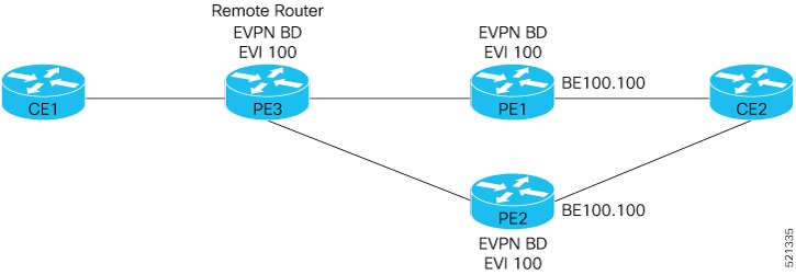
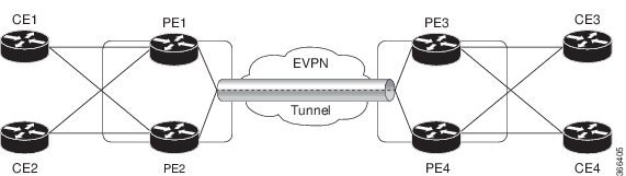
Consider a CE device connected to two PE devices through bundle-Ethernet interface 22001. Configure multiple services on bundle Ethernet sub-interfaces.

Procedure


Step 1

Configure attachment circuits.

Consider bundle-Ether22001 ES, and configure multiple services on sub-interface.

Example:


Router# configure
Router(config)# interface Bundle-Ether22001.12 l2transport
Router(config-l2vpn-subif)# encapsulation dot1q 1 second-dot1q 12
Router(config-l2vpn-subif)# exit
Router(config-l2vpn)# exit
Router(config)# interface Bundle-Ether22001.13 l2transport
Router(config-l2vpn-subif)# encapsulation dot1q 1 second-dot1q 13
Router(config-l2vpn-subif)# exit
Router(config-l2vpn)# exit
Router(config)# interface Bundle-Ether22001.14 l2transport
Router(config-l2vpn-subif)# encapsulation dot1q 1 second-dot1q 14
Router(config-l2vpn-subif)# exit
Router(config-l2vpn)# exit
Router(config)# interface Bundle-Ether22001.1 l2transport
Router(config-l2vpn-subif)# encapsulation dot1q 1 second-dot1q 1
Router(config-l2vpn-subif)# exit
Router(config-l2vpn)# exit
Router(config)# interface Bundle-Ether22001.2 l2transport
Router(config-l2vpn-subif)# encapsulation dot1q 1 second-dot1q 2
Router(config-l2vpn-subif)# exit
Router(config-l2vpn)# exit
Router(config)# interface Bundle-Ether22001.3 l2transport
Router(config-l2vpn-subif)# encapsulation dot1q 1 second-dot1q 3
Router(config-l2vpn-subif)# exit
Router(config-l2vpn)# exit
Router(config)# interface Bundle-Ether22001.4 l2transport
Router(config-l2vpn-subif)# encapsulation dot1q 1 second-dot1q 4
Router(config-l2vpn-subif)# commit

Step 2

Configure EVPN E-Line xconnect service.

Example:

Router# configure
Router(config)# interface Bundle-Ether22001.11 l2transport
Router(config-l2vpn-subif)# encapsulation dot1q 1 second-dot1q 11
Router(config-l2vpn-subif)# rewrite ingress tag pop 2 symmetric
Router(config-l2vpn-subif)# commit
Router(config-l2vpn-subif)# exit
Router# configure
Route(config)# l2vpn
Router(config-l2vpn)# xconnect group xg22001
Router(config-l2vpn-xc)# p2p evpn-vpws-mclag-22001
Router(config-l2vpn-xc-p2p)# interface Bundle-Ether22001.11  
Router(config-l2vpn-xc-p2p)# neighbor evpn evi 22101 target 220101 source 220301
Router(config-l2vpn-xc-p2p-pw)# commit

Step 3

Configure native EVPN.

Example:

Router # configure
Router (config)# evpn
Router (config-evpn)# interface Bundle-Ether22001
Router (config-evpn-ac)# ethernet-segment identifier type 0 ff.ff.ff.ff.ff.ff.ff.ff.ee
Router (config-evpn-ac-es)# bgp route-target 2200.0001.0001
Router (config-evpn-ac-es)# exit
Router (config-evpn)# evi 24001 
Router (config-evpn-evi)# bgp
Router (config-evpn-evi-bgp)# route-target import 64:24001  
Router (config-evpn-evi-bgp)# route-target export 64:24001
Router (config-evpn-evi-bgp)# exit
Router (config-evpn-evi)# exit
Router (config-evpn)# evi 21006
Router (config-evpn-evi)# bgp
Router (config-evpn-evi-bgp)# route-target 64:10000
Router (config-evpn-evi-bgp)# exit
Router (config-evpn-evi)# exit
Router (config-evpn)# evi 22101 
Router (config-evpn-evi)# bgp
Router (config-evpn-evi-bgp)# route-target import 64:22101
Router (config-evpn-evi-bgp)# route-target export 64:22101
Router (config-evpn-evi-bgp)# exit
Router (config-evpn-evi)# exit
Router (config-evpn)# evi 22021
Router (config-evpn-evi)# bgp
Router (config-evpn-evi-bgp)# route-target import 64: 22021
Router (config-evpn-evi-bgp)# route-target export 64: 22021
Router (config-evpn-evi-bgp)# exit
Router (config-evpn-evi)# exit
Router (config-evpn-evi)# advertise-mac
Router (config-evpn-evi)# exit
Router (config-evpn)# evi 22022
Router (config-evpn-evi)# bgp
Router (config-evpn-evi-bgp)# route-target import 64: 22022
Router (config-evpn-evi-bgp)# route-target export 64: 22022
Router (config-evpn-evi-bgp)# exit
Router (config-evpn-evi)# advertise-mac
Router (config-evpn-evi)# commit

Step 4

Running configuration of EVPN multiple services per Ethernet segment.

Example:


/* Configure attachment circuits */
interface Bundle-Ether22001.12 l2transport 
encapsulation dot1q 1 second-dot1q 12
!
interface Bundle-Ether22001.13 l2transport 
encapsulation dot1q 1 second-dot1q 13
!
interface Bundle-Ether22001.14 l2transport 
encapsulation dot1q 1 second-dot1q 14
!
interface Bundle-Ether22001.1 l2transport
 encapsulation dot1q 1 second-dot1q 1
!
interface Bundle-Ether22001.2 l2transport 
encapsulation dot1q 1 second-dot1q 2
!
interface Bundle-Ether22001.3 l2transport 
encapsulation dot1q 1 second-dot1q 3
!
interface Bundle-Ether22001.4 l2transport 
encapsulation dot1q 1 second-dot1q 4


/* Configure EVPN E-Line xconnect service */
interface Bundle-Ether22001.11 l2transport 
  encapsulation dot1q 1 second-dot1q 11
  rewrite ingress tag pop 2 symmetric
 !
l2vpn 
xconnect group xg22001  
p2p evpn-vpws-mclag-22001  
 interface Bundle-Ether22001.11  
 neighbor evpn evi 22101 target 220101 source 220301  
!
  !  
/* Configure Native EVPN */
Evpn
 interface Bundle-Ether22001  
  ethernet-segment   identifier type 0 ff.ff.ff.ff.ff.ff.ff.ff.ee 
  bgp route-target 2200.0001.0001
  !
  evi 24001  
   bgp  
    route-target import 64:24001   
    route-target export 64:24001
   !
   evi 21006  
    bgp   
      route-target 64:100006
   !
    evi 22101  
     bgp  
       route-target import 64:22101   
       route-target export 64:22101
     !
   evi 22021 
    bgp   
      route-target import 64:22021  
      route-target export 64:22021  
    !  
    advertise-mac
  !
  evi 22022  
   bgp   
    route-target import 64:22022  
    route-target export 64:22022  
   ! 
    advertise-mac
  !

Step 5

Use show l2vpn xconnect summary and show l2vpn xconnect group xg22001 xc-name evpn-vpws-mclag-22001 commands to verify if each of the services is configured on the sub-interface.

Example:


Router# show l2vpn xconnect summary
Number of groups: 6
Number of xconnects: 505  Up: 505  Down: 0  Unresolved: 0 Partially-programmed: 0  
AC-PW: 505  AC-AC: 0  PW-PW: 0 Monitor-Session-PW: 0
Number of Admin Down segments: 0
Number of MP2MP xconnects: 0  
 Up 0 Down 0  
Advertised: 0 Non-Advertised: 0
 

Router# show l2vpn xconnect group xg22001 xc-name evpn-vpws-mclag-22001
Fri Sep 1 17:28:58.259 UTC
Legend: ST = State, UP = Up, DN = Down, AD = Admin Down, UR = Unresolved,
SB = Standby, SR = Standby Ready, (PP) = Partially Programmed
XConnect 																															Segment 1 										Segment 2
Group 				Name 																		ST 				Description ST 					Description 																ST
------------------------ ----------------------------- -----------------------------------
xg22001 	evpn-vpws-mclag-22001 		UP 			BE22001.101 	UP 					EVPN 22101, 220101,64.1.1.6 UP
------------------------------------------------------------------------------------------

Hierarchical EVPN access pseudowire

A hierarchical EVPN access pseudowire is a network capability that

  • reduces the number of pseudowires between network provider edge (N-PE) devices

  • connects user provider edge (U-PE) devices to N-PE devices using EVPN access pseudowires for each VPN instance, and

  • links customer edge (CE) devices to U-PE devices through attachment circuits.

This capability optimizes network scalability by minimizing the pseudowire count on the provider edge, simplifying management and improving efficiency.

  • Pseudowire (PW): A virtual point-to-point connection that emulates a physical wire over a packet-switched network.

  • Network Provider Edge (N-PE): The provider’s edge device that terminates pseudowires.

  • User Provider Edge (U-PE): The device connecting customer edge devices to the provider network through pseudowires.

  • Attachment Circuit: The physical or logical link connecting a CE device to a U-PE device.

Table 2. Feature History Table

Feature Name

Release Information

Feature Description

Hierarchical EVPN access pseudowire

Release 25.3.1

Introduced in this release on: Centralized Systems (8400 [ASIC: K100]) (select variants only*)

*This feature is now supported on the Cisco 8404-SYS-D routers.

Hierarchical EVPN access pseudowire

Release 24.4.1

Introduced in this release on: Fixed Systems (8700) (select variants only*)

* The Hierarchical EVPN Access Pseudowire functionality is now extended to the Cisco 8712-MOD-M routers.

Hierarchical EVPN access pseudowire

Release 24.3.1

Introduced in this release on: Modular Systems (8800 [LC ASIC: P100]) (select variants only*)

* The Hierarchical EVPN Access Pseudowire functionality is now extended to:

  • 8212-48FH-M

  • 8711-32FH-M

  • 88-LC1-52Y8H-EM

  • 88-LC1-12TH24FH-E

Hierarchical EVPN access pseudowire

Release 24.2.11

Introduced in this release on: Modular Systems (8800 [LC ASIC: P100]) (select variants only*)

This feature enables you to configure EVPN VPWS in the access node under the same bridge domain as EVPN in the core and helps to build a PW to the nearest high-end PE that stitches those access circuits using EVPN. Therefore, the access nodes can leverage the benefits of EVPN.

This feature also allows you to reduce the number of pseudowires (PWs) between the network provider edge (N-PE) devices by replacing PE devices with user provider edge (U-PE) and network provider edge (N-PE) devices. This feature prevents signaling overhead and packet replication.

* This feature is supported only on routers with 88-LC1-36EH line cards.

Hierarchical EVPN access pseudowire model

The hierarchical EVPN access pseudowire is a network feature that reduces the number of PWs between N-PE devices. This capability is accomplished by introducing a two-tier provider edge architecture where:

  • U-PE devices connect to CE devices through attachment circuits and establish EVPN access pseudowires for each VPN instance to the N-PE devices.

  • N-PE devices communicate with other N-PE devices in the core network, handling the aggregation of pseudowires from multiple U-PE devices.

How hierarchical EVPN access pseudowire works

Summary

The key components involved in the hierarchical EVPN access pseudowire are:

  • U-PE1: Connects to the CE1 device through an attachment circuit and transports CE1 traffic over an EVPN access PW.

  • N-PE1: Receives the access PW from U-PE1 and connects to other N-PE devices (such as N-PE2) within the EVPN core.

  • N-PE2: Part of the EVPN core, interconnected with N-PE1.

  • AC: The physical or logical link between CE1 and U-PE1.

The hierarchical EVPN access pseudowire process connects the customer edge device to the EVPN core by transporting traffic from U-PE1 over an access pseudowire to N-PE1. N-PE1 then forwards this traffic within the EVPN core to other network provider edges, maintaining a clear separation between the access and core layers.

Workflow

These stages describe how hierarchical EVPN access pseudowire works.

  1. The U-PE1 device establishes an attachment circuit connection to CE1.
  2. U-PE1 transports CE1 traffic over an EVPN access pseudowire to N-PE1.
  3. On N-PE1, the access pseudowire from U-PE1 is treated similarly to an attachment circuit.
  4. U-PE1 operates outside the EVPN core and is not part of the core network with other N-PE devices.
  5. N-PE1 forwards traffic received from the access pseudowire to core pseudowires within the EVPN core, connecting to other N-PE devices such as N-PE2.

Result

This process enables hierarchical EVPN access by separating the user provider edge from the core provider edge devices, allowing efficient transport of customer traffic from the attachment circuit through access pseudowires into the EVPN core.

Configure hierarchical EVPN access pseudowire

Configure the hierarchical EVPN access pseudowire feature on U-PE and N-PE devices to enable efficient Layer 2 VPN connectivity.

This task applies when setting up hierarchical EVPN access pseudowires to interconnect U-PE and N-PE routers in an EVPN environment.

Procedure


Step 1

Configure the U-PE device.

Example:

Router# configure 
Router(config)# l2vpn 
Router(config-l2vpn)# xconnect group XG1
Router(config-l2vpn-xc)# p2p P1
Router(config-l2vpn-xc-p2p)# interface TenGigE0/0/0/31
Router(config-l2vpn-xc-p2p)# neighbor evpn evi 4 target 33 source 33
Router(config-l2vpn-xc-p2p-pw)# commit

Step 2

Configure the N-PE device.

Example:


Router# configure 
Router(config)# l2vpn 
Router(config-l2vpn)# bridge group evpn
Router(config-l2vpn-bg)# bridge-domain evpn1
Router(config-l2vpn-bg-bd)# neighbor evpn evi 4 target 33
Router(config-l2vpn-bg-bd)# evi 1
Router(config-l2vpn-bg-bd-evi)# commit

Step 3

Use the show l2vpn bridge-domain bd-name evpn1 command to verify the EVPN state, and the list of access PWs.

The sample output on N-PE1 shows it processing EVPN access pseudowire traffic from U-PE1 like an attachment circuit and forwarding it into the EVPN core to connect with other N-PE devices.

Example:


Router:N-PE1# show l2vpn bridge-domain bd-name evpn1
Wed Jun 16 09:22:30.328 EDT
Legend: pp = Partially Programmed.
Bridge group: evpn, bridge-domain: evpn1, id: 1, state: up, ShgId: 0, MSTi: 0
  Aging: 300 s, MAC limit: 4000, Action: none, Notification: syslog
  Filter MAC addresses: 0
  ACs: 0 (0 up), VFIs: 0, PWs: 1 (1 up), PBBs: 0 (0 up), VNIs: 0 (0 up)
  List of EVPNs:
    EVPN, state: up
  List of ACs:
  List of Access PWs:
      EVPN 4,33,192.168.0.4, state: up, Static MAC addresses: 0
  List of VFIs:
  List of Access VFIs:

The hierarchical EVPN access pseudowire is configured successfully, enabling Layer 2 connectivity between U-PE and N-PE devices.

Layer 2 fast reroute

A layer 2 fast reroute (FRR) is a network capability that

  • redirects traffic during link or node failures in a layer 2 network

  • establishes backup paths to enable rapid switchover and minimize disruption, and

  • prevents traffic loss when a PE-CE link fails before the remote PE receives the mass withdrawal message.

Supported Layer 2 fast reroute services

Layer 2 fast reroute is supported on these services:

  • E-LAN service—is a multipoint-to-multipoint Layer 2 connection, requiring FRR to handle traffic rerouting across multiple endpoints and maintain seamless connectivity within the LAN segment.

  • E-Line service—is a point-to-point Layer 2 connection, so FRR focuses on rerouting traffic between two endpoints.

Layer 2 fast reroute for E-LAN services

A Layer 2 fast reroute (FRR) for E-LAN services is a network capability that

  • provides rapid traffic rerouting in the event of a link or node failure within a multipoint Layer 2 network

  • improves network reliability by maintaining connectivity among multiple endpoints, and

  • ensures service continuity with minimal disruption by pre-establishing backup paths that accommodate the multipoint topology.

Table 3. Feature History Table

Feature Name

Release Information

Feature Description

Layer 2 fast reroute for E-LAN services

Release 25.3.1

Introduced in this release on: Centralized Systems (8400 [ASIC: K100])(select variants only*)

* This feature is now supported on Cisco 8404-SYS-D routers.

Layer 2 fast reroute for E-LAN services

Release 24.4.1

Introduced in this release on: Fixed Systems(8200, 8700);Modular Systems (8800 [ASIC: P100]) (select variants only*)

*This feature is now supported on:

  • 8212-32FH-M

  • 8711-32FH-M

  • 88-LC1-12TH24FH-E

Layer 2 fast reroute for E-LAN services

Release 24.3.1

Introduced in this release on: Fixed Systems (8200, 8700); Centralized Systems (8600); Modular Systems (8800 [LC ASIC: Q100, Q200, P100])

Fast reroute minimizes traffic loss by quickly redirecting traffic to a backup path in the event of a link failure, ensuring fast convergence and maintaining the service continuity.

This feature introduces the convergence reroute  command.

MAC address handling during AC failure in Layer 2 fast reroute for E-LAN service

In an E-LAN service, local hosts are associated with a specific bridge port based on their MAC addresses, independent of the AC status. When Layer 2 FRR is enabled and an AC fails, the MAC addresses remain linked to the L2 FRR-enabled AC and are not flushed. This mechanism ensures continuous MAC address association despite changes in the AC state, maintaining network stability and connectivity.

Layer 2 fast reroute in all-active multihoming mode

In all-active redundancy mode or single-active mode, configure the AC-backup function to enable fast traffic redirection by using the service label of the all-active peer. This configuration ensures that hosts or MAC addresses remain permanently associated with the AC, maintaining stable and continuous network connectivity during failover events.

Benefits of Layer 2 fast reroute for E-LAN service

L2 FRR for E-LAN service provides several key benefits that enhance network performance and reliability:

  • delivers fast and predictable convergence, ensuring minimal disruption during failover events.

  • enables rapid failure notification even in large ring topologies with many nodes.

  • supports manual configuration to achieve predictable failover behavior tailored to network requirements.

  • requires no changes to the existing network topology, simplifying deployment and maintenance.

How Layer 2 fast reroute for EVPN multihomed E-LAN services work

Summary

The key components involved in the L2 FRR process for EVPN multihomed E-LAN services are:

  • CE2: Customer edge device multihomed to PE1 and PE2.

  • PE1 and PE2: Provider edge routers operating in EVPN active-active or single-active mode, enabled with L2 FRR, and connected to PE3 over the MPLS core.

  • PE3: Remote Provider edge router connected to CE1.

  • FRR label: A backup path label allocated per Ethernet VPN Instance (EVI) for traffic protection.

The L2 FRR process for EVPN multihomed E-LAN services enables fast traffic redirection by pre-programming backup paths and using FRR labels to ensure seamless failover when a link to a customer edge device fails, minimizing service disruption. This process involves multihomed provider edge routers distributing and forwarding traffic with rapid failover triggered upon link failure.

Workflow

These stages describe how the L2 FRR for EVPN multihomed E-LAN services work.

  1. CE1 sends traffic to PE3.
  2. PE3 distributes the traffic across PE1 and PE2.
  3. PE1 and PE2 forward the traffic to CE2.
  4. If the PE1-CE2 link fails, PE1 triggers L2 FRR and redirects traffic to PE2 until network convergence completes.
  5. When L2 FRR is enabled on PE1, the backup path to PE2 is pre-programmed in hardware. Upon detecting the failure on the CE2 link, PE1 uses this pre-programmed backup path.
  6. PE2 allocates and advertises an FRR label for the protected traffic.
  7. All incoming traffic to PE1 is encapsulated with PE2’s FRR label and forwarded to PE2.
  8. PE2 receives the traffic with the FRR label and forwards it to CE2.

Result

This process ensures fast reroute of traffic in EVPN multihoming modes, minimizing traffic disruption during link failures by pre-establishing backup paths and labels for seamless failover.

Restrictions for Layer 2 fast reroute for E-LAN service

  • This feature is supported on EVPN all-active or single-active mode.

  • This feature applies only to unicast traffic.

  • This feature is not supported for BUM traffic.

Configure Layer 2 fast reroute for E-LAN service

Enable L2 FRR on a PE router to provide fast convergence in an E-LAN EVPN multihoming network.

Use this task to configure L2 FRR on both PE routers in an E-LAN EVPN multihoming setup to ensure rapid failover and maintain service continuity.

Procedure

Step 1

Associate the Ethernet segment with the bundle interface.

Example:
Router# configure
Router(config)# l2vpn
Router(config-l2vpn)# bridge group bg1
Router(config-l2vpn-bg)# bridge-domain bd1
Router(config-l2vpn-bg-bd)# interface Bundle-Ether4.1
Router(config-l2vpn-bg-bd-ac)#exit
Router(config-l2vpn-bg-bd)# evi 1
Router(config-l2vpn-bg-bd-evi)# exit
Router(config-l2vpn-bg-bd)# exit
Router(config-l2vpn-bg)# bridge-domain bd2
Router(config-l2vpn-bg-bd)# interface Bundle-Ether4.2
Router(config-l2vpn-bg-bd-ac)# exit
Router(config-l2vpn-bg-bd)# exit
Router(config-l2vpn-bg)# exit
Router(config-l2vpn)#

Step 2

Enable L2 FRR.

Example:
Router# configure
Router(config)# evpn
Router(config-evpn)# evi 1
Router(config-evpn-instance)# advertise-mac
Router(config-evpn-instance-mac)# exit
Router(config-evpn-instance)# exit
Router(config-evpn)# evi 2
Router(config-evpn-instance)# advertise-mac
Router(config-evpn-instance-mac)# exit
Router(config-evpn-instance)# exit
Router(config-evpn)# interface Bundle-Ether4
Router(config-evpn-ac)# ethernet-segment
Router(config-evpn-ac-es)# identifier type 0 40.00.00.00.00.00.00.00.01
Router(config-evpn-ac-es)# load-balancing-mode single-active
Router(config-evpn-ac-es)# convergence
Router(config-evpn-ac-es-conv)# reroute
Router(config-evpn-ac-es)# exit
Router(config-evpn-ac# exit
Router(config-evpn)# exit
Router(config)# exit

Step 3

Use show evpn ethernet-segment carving detail and show l2vpn forwarding interface BE4.1 private location 0/RP0/CPU0 commands to verify L2 FRR configuration.

Example:
Router# show evpn ethernet-segment carving detail
...Ethernet Segment Id      Interface                          Nexthops            
------------------------ ---------------------------------- --------------------
0040.0000.0000.0000.0001 BE4                                4.5.6.7
                                                            5.6.7.8
  ES to BGP Gates   : Ready
  ES to L2FIB Gates : Ready
  Main port         :
     Interface name : Bundle-Ether4
     Interface MAC  : 00c9.c654.9a04
     IfHandle       : 0x7800008c
     State          : Up
     Redundancy     : Not Defined
  ESI ID            : 1
  ESI type          : 0
     Value          : 0040.0000.0000.0000.0001
  ES Import RT      : 4000.0000.0000 (from ESI)
  Topology          :
     Operational    : MH, Single-active
     Configured     : Single-active (AApS)
  Service Carving   : Auto-selection
     Multicast      : Disabled
  Convergence    : Reroute 
  Peering Details   : 2 Nexthops
     4.5.6.7 [MOD:P:00:T]
     5.6.7.8 [MOD:P:00:T]
  Service Carving Synchronization:
     Mode           : NTP_SCT
     Peer Updates   :
                 4.5.6.7 [SCT: 2025-01-22 17:01:01.1737583]
                 5.6.7.8 [SCT: 2025-01-22 17:00:36.1737583]
  Service Carving Results:
     Forwarders     : 2
     Elected        : 1
            EVI E   :        2
     Not Elected    : 1
            EVI NE  :        1
  EVPN-VPWS Service Carving Results:
     Primary        : 0
     Backup         : 0
     Non-DF         : 0
  MAC Flush msg     : STP-TCN
  Peering timer     : 3 sec [not running]
  Recovery timer    : 30 sec [not running]
  Carving timer     : 0 sec [not running]
  Revert timer      : 0 sec [not running]
  HRW Reset timer   : 5 sec [not running]
  Local SHG label   : 24008
     IPv6_Filtering_ID : 1:16
  Remote SHG labels : 1
              24007 : nexthop 5.6.7.8
  Access signal mode: Bundle OOS
  ...
Router# show l2vpn forwarding interface BE4.1 private location 0/RP0/CPU0  
Wed Jan 22 17:02:01.387 EST

Xconnect ID 0xc0000002

  Xconnect info:
    xcon_status=Up, xcon_bound=TRUE, switching_type=0, data_type=12
    xcon_name=

    Object: XCON
    Base info: version=0xaabbcc13, flags=0x3110, type=2, object_id=UNSPECIFIED, reserved=0
    

  AC info:
    xcon_id=0xc0000002, ifh=0x7800008c, subifh=0x78000096, ac_id=0, ac_type=21, status=Bound
    ac_mtu=1500, iw_mode=1, adj=150.0.0.120+Bundle-Ether4,
    r_aps_channel=FALSE, prot_exclusion=FALSE
    rg_id=0, ro_id=0x0000000000000000
    evpn internal label = None
    E-Tree = Root
    FXC local-switch AC xcid = 0x0 (Invalid)
    FXC local-switch PW xcid = 0xffffffff (Invalid)
    EVPN MP route flags = 0x0
    Statistics:
      packets: received 0 (multicast 0, broadcast 0, unknown unicast 0, unicast 0), sent 0
      bytes: received 0 (multicast 0, broadcast 0, unknown unicast 0, unicast 0), sent 0
      MAC move: 0
      packets dropped: PLU 0, tail 0
      bytes dropped: PLU 0, tail 0

    Object: AC
    Base info: version=0xaabbcc11, flags=0x0, type=3, object_id=0x10001000000002d8|v9, reserved=0

    AC Backup info:
      VC label: 24004
      Local VC label: 0
      Backup Pseudowire XC ID: 0x0
      Statistics:
        packets: received 0, sent 0
        bytes: received 0, sent 0
        packets dropped: PLU 0, tail 0, out of order 0
        bytes dropped: PLU 0, tail 0, out of order 0

      Object: AC_BACKUP
      Base info: version=0xaabbcc39, flags=0x0, type=43, object_id=0x1000100000000300|v1, reserved=0
        Time (~200ms)     Event                     Flags
        =============     =====                     =====
        Jan 22 17:00:58.4 Create                      0x0  -  -
        -------------------------------------------------

      Nexthop info:
        nh_addr=5.6.7.8,
        ecd_plat_data_valid=TRUE, ecd_plat_data_len=104, plat_data_size=232
        child_count=0, child_evpn_ole_count=2, child_mac_count=0, child_pwhe_mp_count=0, child_ac_backup_count=2,
        child_vni_count=0, child_ifl_count=0, child_sg_count=0

        Object: NHOP
        Base info: version=0xaabbcc14, flags=0x4010, type=7, object_id=0x10001000000002f4|v5, reserved=0
        
    bp_seg1_type=0x3, mtu=1500
    is_flooding_disabled=FALSE, is_mac_learning_disabled=FALSE, is_mac_port_down_flush_disabled=FALSE,
   EVPN ESI ID: 0
   EVPN SHG Local Label: None
   EVPN SHG Remote Labels: 0
    MAC learning: enabled
    Software MAC learning: enabled
    MAC port down flush: enabled
    Flooding:
      Broadcast & Multicast: enabled
      Unknown unicast: enabled
    MAC aging time: 300 s, Type: inactivity
    MAC limit: none
    MAC Secure: disabled, Logging: disabled, Accept-Shutdown: enabled
    DHCPv4 snooping: profile not known on this node, disabled
    Dynamic ARP Inspection: disabled, Logging: disabled
    IP Source Guard: disabled, Logging: disabled
    IGMP snooping profile: profile not known on this node
    MLD snooping profile: profile not known on this node
    Router guard disabled
    vES:disabled
    Etree Leaf:disabled
    STP participating: disabled
    Storm control: disabled
    Main port: Bundle-Ether4, MSTI: 2

    Object: BRIDGE_PORT
    Base info: version=0xaabbcc1a, flags=0x0, type=12, object_id=0x10001000000002d9|v6, reserved=0

L2 FRR is enabled on the PE routers, providing fast failover in the E-LAN EVPN multihoming network. The Ethernet segment is associated with the bundle interface, and convergence reroute is active, ensuring rapid recovery from failures.

Layer 2 fast reroute for E-Line service

A Layer 2 fast reroute (FRR) for E-Line services is a network capability that

  • provides rapid traffic rerouting in the event of a link or node failure

  • improves network reliability, and

  • ensures service continuity with minimal disruption by pre-establishing backup paths.

Table 4. Feature History Table

Feature Name

Release Information

Feature Description

Layer 2 fast reroute for E-Line services

Release 25.2.1

Introduced in this release on: Centralized Systems (8400 [ASIC: K100])(select variants only*)

*This feature is now supported on the Cisco 8404-SYS-D routers.

Layer 2 fast reroute for E-Line services

Release 25.1.1

Introduced in this release on: Fixed Systems 8010 [ASIC: A100]) (select variants only*)

You can now ensure faster convergence and uninterrupted service by redirecting the traffic using the EVPN pseudowire (PW) in an E-Line configuration when a dual-homing link fails.

*This feature is now supported on:

  • 8011-4G24Y4H-I

Minimize traffic loss with Layer 2 fast reroute for E-Line service

Layer 2 fast reroute protects the provider edge–customer edge (PE-CE) connection by quickly redirecting traffic through a backup path when a primary link fails. This feature minimizes traffic loss and ensures rapid network convergence. If a local link failure occurs, traffic is rerouted to a peer PE, which then forwards it to the CE. In an E-Line service, an EVPN pseudowire establishes a point-to-point Layer 2 connection over an IP/MPLS network using EVPN. All traffic is redirected to the CE without involving MAC address learning or forwarding.

Benefits of Layer 2 fast reroute for E-Line service
  • Achieves fast convergence with a 50 ms target failover time.

  • Protects PE-CE links by rerouting traffic to a peer PE in case of local link failure.

  • Maintains the same topology, requiring no additional network changes.

  • Ensures minimal traffic disruption and rapid recovery in E-Line services.

How Layer 2 fast reroute for EVPN multihomed E-Line services work

Summary

The key components involved in the Layer 2 fast reroute process for EVPN multihomed E-Line services are:

  • CE2: A customer edge device connected to both PE1 and PE2 as a multihomed device.

  • PE1 and PE2: Provider edge routers operating in EVPN active-active or single-active mode, enabled with L2 FRR and assigned FRR labels per EVI for backup paths.

  • PE3: A remote provider edge router connected to CE1 and the MPLS core network.

The Layer 2 FRR process for EVPN multihomed E-Line services rapidly switches traffic from a failed PE to a backup PE using pre-assigned FRR labels.

Workflow

These stages describe how Layer 2 FRR for EVPN multihomed E-Line services work.

  1. Normal traffic flow: CE1 sends traffic to PE3. PE3 distributes the traffic to PE1 and PE2, with PE1 acting as the Designated Forwarder (DF). PE1 and PE2 forward the traffic to CE2.
  2. Failover scenario: When the link between PE1 and CE2 fails, PE1 detects the failure on the access side.
  3. Traffic redirection: PE1 redirects incoming traffic by encapsulating it with PE2’s FRR label and forwards it to PE2 over the pre-programmed backup path.
  4. Traffic forwarding by PE2: Upon receiving the FRR-labeled traffic, PE2 forwards it to CE2 through the attachment circuit (AC), even if the AC is in a blocking state.
  5. Route update: Meanwhile, PE3 updates its routes to send traffic directly to PE2 until the primary link is restored.

Result

This process ensures rapid failover and minimal traffic disruption in EVPN multihomed E-Line services by pre-establishing backup paths and enabling seamless traffic redirection upon link failure.

Restrictions for Layer 2 fast reroute for E-Line service

  • This feature is supported on EVPN all-active or single-active mode.

  • This feature applies only to unicast traffic.

  • This feature is not supported for BUM traffic.

Configure layer 2 fast reroute for E-Line service

Enable L2 FRR on a PE router to enhance network resilience in an E-LINE EVPN multihoming environment.

This task applies to configuring L2 FRR in an EVPN E-Line service where multihoming is deployed with single-active load balancing mode.

Procedure

Step 1

Configure L2 FRR on a PE router in the E-LINE EVPN multihoming network.

Example:
Router(config)# evpn
Router(config-evpn)# evi 1
Router(config-evpn-instance)# exit
Router(config-evpn)# evi 2
Router(config-evpn-instance)# exit
Router(config-evpn)# interface Bundle-Ether4
Router(config-evpn-ac)# ethernet-segment
Router(config-evpn-ac-es)# identifier type 0 40.00.00.00.00.00.00.00.01
Router(config-evpn-ac-es)# load-balancing-mode single-active
Router(config-evpn-ac-es)# convergence
Router(config-evpn-ac-es-conv)# reroute
Router(config-evpn-ac-es-conv)# exit
Router(config-evpn-ac-es)# exit
Router(config-evpn-ac)# exit
Router(config-evpn)# exit
Router(config)#

Step 2

Use show evpn ethernet-segment carving detail and show l2vpn forwarding interface BE4.1 private location 0/RP0/CPU0 commands to verify the L2 FRR EVPN E-LINE configuration and status.

Example:
Router# show evpn ethernet-segment carving detail 
Wed Jan 22 17:15:05.606 EST
...

Ethernet Segment Id      Interface                          Nexthops            
------------------------ ---------------------------------- --------------------
0040.0000.0000.0000.0001 BE4                                4.5.6.7
                                                            5.6.7.8
  ES to BGP Gates   : Ready
  ES to L2FIB Gates : Ready
  Main port         :
     Interface name : Bundle-Ether4
     Interface MAC  : 00c9.c654.9a04
     IfHandle       : 0x7800008c
     State          : Up
     Redundancy     : Not Defined
  ESI ID            : 1
  ESI type          : 0
     Value          : 0040.0000.0000.0000.0001
  ES Import RT      : 4000.0000.0000 (from ESI)
  Topology          :
     Operational    : MH, Single-active
     Configured     : Single-active (AApS)
  Service Carving   : Auto-selection
     Multicast      : Disabled
  Convergence    : Reroute
  Peering Details   : 2 Nexthops
     4.5.6.7 [MOD:P:00:T]
     5.6.7.8 [MOD:P:00:T]
  Service Carving Synchronization:
     Mode           : NTP_SCT
     Peer Updates   :
                 4.5.6.7 [SCT: 2025-01-22 17:13:55.1737584]
                 5.6.7.8 [SCT: 2025-01-22 17:06:30.1737583]
  Service Carving Results:
     Forwarders     : 2
     Elected        : 0
     Not Elected    : 0
  EVPN-VPWS Service Carving Results:
     Primary        : 2
       EVI:ETag P   :      1:2,     2:4
     Backup         : 0
     Non-DF         : 0
  MAC Flush msg     : STP-TCN
  Peering timer     : 3 sec [not running]
  Recovery timer    : 30 sec [not running]
  Carving timer     : 0 sec [not running]
  Revert timer      : 0 sec [not running]
  HRW Reset timer   : 5 sec [not running]
  Local SHG label   : 24008
     IPv6_Filtering_ID : 1:16
  Remote SHG labels : 1
              24007 : nexthop 5.6.7.8
  Access signal mode: Bundle OOS
Router# show l2vpn forwarding interface BE4.1 private location 0/RP0/CPU0 
Wed Jan 22 17:15:29.510 EST

Xconnect ID 0xc0000002

  Xconnect info:
    xcon_status=Up, xcon_bound=TRUE, switching_type=0, data_type=4
    xcon_name=xg1:xc1

    Object: XCON
    Base info: version=0xaabbcc13, flags=0x110, type=2, object_id=UNSPECIFIED, reserved=0
    

  AC info:
    xcon_id=0xc0000002, ifh=0x7800008c, subifh=0x78000096, ac_id=0, ac_type=21, status=Bound
    ac_mtu=1500, iw_mode=0, adj=150.0.0.120+Bundle-Ether4,
    r_aps_channel=FALSE, prot_exclusion=FALSE
    rg_id=0, ro_id=0x0000000000000000
    evpn internal label = None
    E-Tree = Root
    FXC local-switch AC xcid = 0x0 (Invalid)
    FXC local-switch PW xcid = 0x0 (Invalid)
    EVPN MP route flags = 0x4
    Main port: Bundle-Ether4, MSTI: 3
    Statistics:
      packets: received 0, sent 0
      bytes: received 0, sent 0
      packets dropped: MTU exceeded 0, other 0

    Object: AC
    Base info: version=0xaabbcc11, flags=0x0, type=3, object_id=0x100010000000032a|v5, reserved=0

    AC Backup info:
      VC label: 24012
      Local VC label: 24012
      Backup Pseudowire XC ID: 0x20000005
      Statistics:
        packets: received 0, sent 0
        bytes: received 0, sent 0
        packets dropped: PLU 0, tail 0, out of order 0
        bytes dropped: PLU 0, tail 0, out of order 0

      Object: AC_BACKUP
      Base info: version=0xaabbcc39, flags=0x0, type=43, object_id=0x100010000000032b|v1, reserved=0
      

      Nexthop info:
        nh_addr=5.6.7.8,
        ecd_plat_data_valid=TRUE, ecd_plat_data_len=104, plat_data_size=232
        child_count=0, child_evpn_ole_count=0, child_mac_count=0, child_pwhe_mp_count=0, child_ac_backup_count=2,
        child_vni_count=0, child_ifl_count=0, child_sg_count=0

        Object: NHOP
        Base info: version=0xaabbcc14, flags=0x4010, type=7, object_id=0x100010000000032c|v3, reserved=0
        

  PW info:
    pw_id=1, 1, nh_valid=TRUE, sig_cap_flags=0x1, context=0x0,
    MPLS, Destination address: 1.2.3.4, evi: 1, ac-id: 1, status: Bound
    Local Pseudowire label: 24013
    Remote Pseudowire label: 24007
    Control word enabled
    EVPN Virtual ES PW: 0
    VFI PW: 0
    Statistics:
      packets: received 0, sent 0
      bytes: received 0, sent 0
      packets dropped: PLU 0, tail 0, out of order 0
      bytes dropped: PLU 0, tail 0, out of order 0

    Object: ATOM
    Base info: version=0xaabbcc12, flags=0x0, type=4, object_id=0x100010000000032d|v3, reserved=0

    Nexthop info:
      nh_addr=1.2.3.4,
      ecd_plat_data_valid=TRUE, ecd_plat_data_len=104, plat_data_size=232
      child_count=2, child_evpn_ole_count=0, child_mac_count=0, child_pwhe_mp_count=0, child_ac_backup_count=0,
      child_vni_count=0, child_ifl_count=0, child_sg_count=0

      Object: NHOP
      Base info: version=0xaabbcc14, flags=0x4010, type=7, object_id=0x100010000000032e|v3, reserved=0
      
    Statistics:
      packets: received 0, sent 0
      bytes: received 0, sent 0
      packets dropped: MTU 0, tail 0, out of order 0
      bytes dropped: MTU 0, tail 0, out of order 0

    PD System Data: Learn key: 0

The PE router is configured for Layer 2 FRR in an EVPN E-Line multihoming setup, enabling rapid failover and improved service availability.

EVPN and L3VPN using route type-5 over BGP-LU with SR

EVPN and L3VPN using Route Type-5 over BGP-LU with SR is a network architecture that

  • combines EVPN and Layer 3 VPN

  • utilizes route type-5 over BGP Layer-3 Unicast (BGP-LU), and

  • leverages segment routing (SR) for advanced traffic engineering.

Table 5. Feature History Table

Feature Name

Release Information

Feature Description

EVPN and L3VPN using route type-5 over BGP-LU with SR

Release 25.2.1

Introduced in this release on: Modular Systems (8800 [LC ASIC: P100])(select variants only*)

Enhance your network infrastructure with our advanced architecture that seamlessly integrates EVPN, L3VPN, and Route Type-5 over BGP-LU over segment routing, offering a scalable, flexible, and resilient solution for service providers and large enterprises. This design combines the versatility of EVPN for Layer 2 services with the robust scalability of L3VPN, ensuring seamless IP connectivity across multiple sites using route type-5.

* This is supported on 88-LC1-12TH24FH-E and 88-LC1-52Y8H-EM.

Key concepts of EVPN and L3VPN using route type-5 over BGP-LU with SR

These concepts outline the foundational principles and functionalities of EVPN, L3VPN, route type-5, BGP Layer-3 Unicast, and Segment Routing:

  • EVPN is a scalable solution for extending Layer 2 connectivity across geographically dispersed sites, supporting mobility, MAC learning, and multihoming.

  • L3VPN provides IP routing services over shared infrastructure, enabling isolated customer traffic across a provider’s network.

  • Route Type-5 allows the advertisement of Layer 3 prefixes (IPv4 or IPv6) in EVPN, bridging Layer 2 and Layer 3 services.

  • BGP Layer-3 Unicast (BGP-LU) distributes unicast IP routes, acting as the control plane to carry both EVPN and L3VPN prefixes.

  • Segment routing (SR) simplifies traffic engineering by encoding the path through the network into the packet headers using segments.

Benefits of EVPN and L3VPN using route type-5 over BGP-LU with SR

EVPN and L3VPN leveraging route type-5 over BGP-LU with SR offer these benefits:

  • Seamless Layer 2 and Layer 3 integration—EVPN offers efficient Layer 2 extensions with MAC address learning through control-plane, eliminating flooding. L3VPN provides scalable VRF-based IP routing, enhancing tenant or service segregation.

  • Service multiplexing—Supports multiple VRFs with unique mappings to BD, BVI, and EVI for granular traffic segmentation.

  • Scalable core with BGP-LU—BGP-LU enables end-to-end LSPs across multiple IGP domains, facilitating inter-domain segment routing transport while decoupling core and service layers.

  • Inter-domain SR transport—BGP-LU facilitates seamless SR between IGP domains.

References

For detailed information and configuration steps for EVPN, L3VPN, BGP-LU, and SR, refer to the configuration guides:

  • BGP Configuration Guide for Cisco 8000 Series Routers

  • L2VPN Configuration Guide for Cisco 8000 Series Routers

  • L3VPN Configuration Guide for Cisco 8000 Series Routers

  • Segment Routing Configuration Guide for Cisco 8000 Series Routers

Sub-second convergence for EVPN with BGP PIC-edge

Sub-second convergence for EVPN with BGP PIC-edge is a network functionality that

  • maintains uninterrupted service during network failures

  • delivers rapid convergence for active-active EVPN ELAN and E-Line services, and

  • enables immediate switchover to backup nexthop path for user traffic when a preferred path becomes unavailable.

Table 6. Feature History Table

Feature Name

Release Information

Feature Description

Sub-second convergence for EVPN with BGP PIC-edge

Release 25.3.1

Introduced in this release on: Fixed Systems (8010 [ASIC: A100], 8200 [ASIC: P100], 8700 [ASIC: P100, K100]); Modular Systems (8800 [LC ASIC: P100])

You can maintain continuous service in multi-homed EVPN deployments using sub-second convergence for EVPN with BGP PIC-edge. This functionality rapidly switches traffic to a backup nexthop path when the preferred nexthop fails, delivering fast convergence and high availability for active-active EVPN E-LAN and E-Line services.

EVPN network resiliency with sub-second BGP PIC-edge convergence

Sub-second convergence for EVPN with BGP PIC-edge enhances network availability and reliability by minimizing service disruptions in large-scale environments where even brief outages affect users and business operations.

Key features include:

  • Preprogrammed primary and backup paths: Both active and standby routes are configured in advance to maintain service continuity during failures.

  • Automatic traffic redirection: The system reroutes traffic seamlessly to backup paths upon primary path failure and restores normal operation quickly when the primary path is available.

  • Rapid convergence for active-active EVPN E-LAN and E-Line services: Multi-homed deployments achieve sub-second recovery times independent of the underlying BGP and EVPN prefixes.

Supported deployment scenarios for sub-second EVPN convergence

The sub-second EVPN convergence supports these deployment scenarios:

When... and remote PE is reachable through... the feature provides...
the remote PE is within the same IGP domain IGP sub-second EVPN convergence for node failure in active-active Multihoming scenarios.
the remote PE is in a different IGP domain BGP-LU sub-second EVPN convergence in inter-IGP domain scenarios.

Benefits of sub-second convergence for EVPN with BGP PIC-edge

These are some of the benefits of sub-second convergence for EVPN with BGP PIC-edge:

  • Rapid traffic recovery: Enables sub-second failover when a primary path or node fails, minimizing traffic disruption for end users.

  • Improved network resiliency: Enhances the ability of the network to quickly recover from failures, supporting high-availability services.

  • Prefix-Independent Convergence (PIC): Pre-programs backup paths in hardware, allowing instant traffic switching without software re-programming of each prefix.

  • Optimized for active-active multihoming: Provides seamless traffic redirection in active-active multihoming scenarios.

  • Scales efficiently for large EVPN deployments.

Limitations of sub-second convergence for EVPN with BGP PIC-edge

  • Sub-second convergence applies only to unicast EVPN traffic. Backup paths can be pre-programmed in hardware only for unicast prefixes.

  • Fast convergence for BUM traffic is not supported.

  • Sub-second convergence is supported only when a single EVPN nexthop path goes down at a time. Multiple simultaneous failures or mass flaps may not achieve sub-second recovery.

  • Use the preferred-nexthop {[highest-ip] [lowest-ip]} command to enable sub-second convergence.

  • Backup path pre-programming relies on hardware capabilities.

How sub-second convergence for EVPN with BGP PIC-edge works

Sub-second EVPN convergence features minimize traffic interruption during network failures by switching to a pre-programmed backup nexthop path without control-plane delay.

Summary

The key components involved in the process are:

  • Primary path: The main route used for forwarding EVPN service traffic.

  • Backup path: An alternate route pre-programmed in hardware to take over if the primary path fails.

  • Forwarding Information Base (FIB): A table that manages path selection and failover.

Workflow

These stages describe how the sub-second EVPN convergence works.

  1. When the preferred path is operational, all traffic is sent using the primary path.
  2. If the primary path fails because of a node failure, link failure, or IGP event, the hardware immediately switches forwarding to the backup path without waiting for the control plane to reconverge.
  3. The system continues forwarding over the backup path until the primary path is restored or a new preferred path is configured.
  4. If the primary path is not restored, the control plane later reconverges and programs the backup path as the sole forwarding path.

Result

Service interruption is minimized, and traffic switchover occurs in less than one second in supported scenarios.

Configure sub-second convergence for EVPN with BGP PIC-edge

Achieve sub-second EVPN convergence by enabling rapid failover through preferred next-hop configuration.

This task applies when you want to optimize EVPN path selection to ensure fast failover between primary and backup paths.

Before you begin

Ensure you have access to the router CLI and necessary privileges to configure EVPN.

Procedure


Step 1

Configure the preferred next-hop for the EVPN instance to optimize path selection for rapid failover.

Example:

Router# configure
Router(config)# evpn
Router(config-evpn)# evi 100
Router(config-evpn-instance)# preferred-nexthop highest-ip
Router(config-evpn-instance)# commit

Step 2

Run the show running-config evpn command to ensure the configuration is active.

Example:

Router#show running-config evpn
evpn
 evi 100
  preferred-nexthop highest-ip
 !
!

The router is configured for sub-second EVPN convergence, with both primary and backup paths pre-programmed to provide rapid and automatic failover.

Layer 3 EVPN IGMP and MLD state synchronization

Layer 3 EVPN IGMP and Multicast Listener Discovery (MLD) state synchronization is a network solution that

  • synchronizes IPv4 IGMP and IPv6 MLD states across multiple PE devices

  • ensures reliable and seamless multicast service delivery in residential fiber-to-the-home (FTTH) deployments, and

  • removes the need for complex L2 and integrated routing and bridging (IRB) configurations by utilizing L3 subinterfaces.

Table 7. Feature History Table

Feature Name

Release Information

Feature Description

Layer 3 EVPN IGMP and MLD state synchronization

Release 25.3.1

Introduced in this release on: Fixed Systems(8200, 8700, 8011)(select variants only*); Modular Systems (8800 [LC ASIC: P100])

You can ensure seamless and reliable multicast delivery in residential FTTH networks with IGMP and MLD state synchronization for L3 using EVPN. This feature synchronizes IPv4 IGMP and IPv6 Multicast Listener Discovery (MLD) states across multiple PE devices using L3 sub-interfaces, eliminating the need for complex L2 or IRB configurations. It supports both VRF and global routing table deployments, providing flexibility for various network designs.

*This feature is supported on:

  • 8212-48FH-M

  • 8711-32FH-M

  • 8712-MOD-M

  • 8011-4G24Y4H-I

Simplified multicast delivery in residential FTTH networks

In many fiber-to-the-home (FTTH) deployments, multicast receivers are located within residential networks where hosts do not communicate with each other. To minimize costs, service providers often deploy basic Layer 2 switches in these networks and connect them to Provider Edge (PE) devices using Layer 2 port channels. However, when PE devices terminate traffic at Layer 2, Integrated Routing and Bridging (IRB) interfaces must be configured to bridge Layer 2 and Layer 3 domains. This adds unnecessary complexity because there is no host-to-host communication in these environments.

Including L2 switching and IRB interfaces in such scenarios increases operational overhead without providing tangible benefits. A simpler architecture can be achieved by terminating access connections as Layer 3 subinterfaces on the PE device. This eliminates the need for IRB interfaces, streamlines forwarding logic, and results in a more efficient and cost-effective design for residential multicast delivery.

Using EVPN for IGMP and MLD state synchronization at Layer 3 ensures consistent IPv4 and IPv6 multicast group membership across multiple PE devices. This approach supports resilient multicast services in residential FTTH networks by leveraging Layer 3 connectivity. The design aligns with RFC 9251, providing robust and scalable multihoming capabilities.

Multihomed topologies for IGMP and MLD state synchronization

A multihomed topology for IGMP and MLD state synchronization is a network design that

  • connects CE devices to multiple PE devices

  • uses L3 subinterfaces for direct connections, and

  • supports multicast state synchronization to ensure uninterrupted service for both IPv4 and IPv6 multicast traffic.

Benefits of Layer 3 EVPN IGMP and MLD state synchronization

Layer 3 EVPN IGMP and MLD state synchronization offers several key benefits:

  • Simplifies network architecture by removing unnecessary Layer 2 switching in residential deployments.

  • Enhances scalability and lowers operational overhead through the adoption of L3 multihoming, as specified in RFC 9251.

  • Boosts multicast performance and reliability by streamlining forwarding processes, improving efficiency across different IP versions.

Guidelines for Layer 3 EVPN IGMP and MLD state synchronization

  • Do not change the standard multicast routing configuration when enabling Layer 3 EVPN IGMP and MLD state synchronization.

  • Use only bundle subinterfaces to support Layer 3 EVPN IGMP and MLD state synchronization.

  • Deploy this feature in both VRF and global routing table environments.

  • Configure all IGMP (IPv4) and MLD (IPv6) parameters—such as timers, versions, and querier settings—identically across all redundancy groups.

  • If static joins are necessary on multihomed ports, configure them identically across redundancy groups because static joins are not synchronized automatically.

  • When using PIM or PIMv6 with IGMP or MLD state synchronization, configure multicast redundancy in all-active mode only; single-active and port-active modes are not supported.

How Layer 3 EVPN IGMP and MLD state synchronization works

In EVPN multihoming, the designated forwarder (DF) exclusively forwards multicast traffic, including IGMP and MLD queries, to the customer edge, while the non-designated forwarder (NDF) blocks duplicates to prevent loops. This IGMP and MLD state synchronization ensures efficient, loop-free multicast delivery by coordinating forwarding roles across Layer 2 and Layer 3 components.

Summary

The key components involved in IGMP and MLD state synchronization are:

  • L3

    • PE1 and PE2: Both act as PE routers running PIM/PIMv6 (Protocol Independent Multicast for IPv4/IPv6) and connect to the customer edge (CE) via Bundle Ethernet interfaces.

    • Global routing table (GRT): Handles unicast and multicast routing.

    • Designated router (DR): Manages multicast group membership.

    • Designated forwarder (DF): Forwards multicast traffic on the shared segment as elected per EVPN rules.

      In EVPN multihoming scenarios, the DF is responsible for forwarding multicast traffic, including IGMP and MLD queries, to the CE. Only the DF PE forwards such traffic, while the Non-Designated Forwarder (NDF) blocks it to prevent duplication and loops. This mechanism ensures that the CE receives a single, loop-free copy of multicast queries and traffic.

    • EVPN A-A (All-active): Enables both PEs to be active and participate in forwarding.

  • L2

    • CE: Device that receives L2 multicast (IGMP/MLD) joins from FTTH subscribers.

IGMP and MLD state synchronization ensures efficient and loop-free multicast delivery in EVPN active-active multihoming environments by coordinating state and forwarding roles among L2 and L3 network components.

Workflow

Figure 1. A sample toplogy for L3 EVPN IGMP and MLD state synchronization

This diagram illustrates the operation of L3 EVPN for synchronizing IGMP and MLD state across PE devices in a dual-homed all-active topology. The goal is to ensure consistent multicast group state between PE1 and PE2 for seamless multicast forwarding, even in the event of a link or device failure.

This example focuses on multicast running in the global routing table (GRT), but the process is the same when multicast operates in a VRF (MVPN).

These stages describe multicast state synchronization:

  1. Reception of IGMP/MLD joins from the customer edge (CE): The CE device sends IGMP (for IPv4) or MLD (for IPv6) membership reports upstream to either PE1 or PE2 over the Layer 2 Bundle Ethernet interface to indicate interest in specific multicast groups.
  2. State learning and actions: The PE that receives the IGMP or MLD join sends a PIM or PIMv6 join message to the core to request the multicast stream. Because both PEs act as PIM or PIMv6 DRs for the Bundle-Ether interface, either PE that receives the IGMP or MLD join will trigger a PIM or PIMv6 join to the core.
  3. State synchronization between PEs: IGMP and MLD state information is synchronized between PE1 and PE2 using EVPN mechanisms. The PEs exchange synchronization messages containing IGMP and MLD states, including group membershipand source details, over the EVPN all-active control plane. This ensures both PEs maintain an identical view of multicast group membership, regardless of which PE received the original join.
  4. Live-live redundancy: IGMP/MLD state synchronization allows the second PE to also send PIM or PIMv6 join towards the core to request the multicast stream. Both PEs receive the multicast stream from the core, ensuring live-live redundancy.
  5. Multicast traffic forwarding: Both PEs receive the multicast traffic, but only the DF sends it through the Bundle-Ether interface. The non-designated forwarder (NDF) does not forward the traffic.
  6. Failure scenario: If the Bundle-Ether interface on the DF fails, the second PE automatically becomes the DF and immediately forwards the multicast stream. This ensures uninterrupted multicast delivery.

Example scenario

  1. A subscriber sends an IGMP join message for a TV multicast group from behind the CE device.

  2. The CE forwards the IGMP join on one of the two bundle links; for example, the join is received by PE1.

  3. Both PE1 and PE2 are designated routers (DRs). Regardless of which PE receives the IGMP join, a Protocol Independent Multicast (PIM) join is sent upstream to request multicast traffic.

  4. PE1 exchanges its IGMP state with PE2 over EVPN active-active synchronization.

  5. When PE2 receives the IGMP state over EVPN A-A, it also sends a PIM join upstream.

  6. PE1 forwards the multicast stream through the Bundle-Ether interface because it is the DF.

  7. If PE1 fails, PE2 already maintains the multicast group state and receives the stream from the core, allowing it to immediately take over forwarding multicast traffic to the subscriber.


Note


Because of IGMP/MLD state synchronization, the process operates the same way if the join is received on PE2, the non-designated forwarder, in step 2.


Configure Layer 3 EVPN IGMP and MLD state synchronization

Enable and maintain synchronized IGMP and MLD multicast group state across dual-homed PE routers in an EVPN all-active multihoming environment to ensure efficient, loop-free multicast delivery.

This task applies to Layer 3 EVPN deployments where PE routers connect to customer edge devices via Bundle Ethernet interfaces, supporting multicast traffic with redundancy and active-active forwarding.

Before you begin

  • Enable and activate the l2vpn evpn address family on peering with route reflectors to allow EVPN control plane messages to be exchanged between PEs.

  • Ensure that the same ESI value is configured under the EVPN settings on both PEs for the Bundle-Ether interface.

    For more details on EVPN configuration, see EVPN MPLS Multihoming.

  • Layer 3 EVPN IGMP and MLD state synchronization requires the standard multicast configuration. For more details, see the Multicast Configuration Guide for Cisco 8000 Series Routers.

Procedure


Step 1

Configure the Ethernet Virtual Instance (EVI) to be used for EVPN synchronization.

  1. Run the evpn route-sync <evi> command if multicast operates in GRT.

    Example:

    Router#config
    Router(config)#evpn route-sync 10
    Router(config-evpn-instance)#commit

    The evpn route-sync <evi> command enables route synchronization for a specific EVI in the GRT. Use this command when multicast operates in the GRT and the ESI and associated bundle subinterfaces are not tied to any VRF. The command ensures that Layer 3 routes for the EVPN instance are synchronized across all PE devices within the GRT.

  2. Run the evpn route-sync <evi> command if multicast operates in default VRF.

    Example:

    Router#config
    Router(config)#evpn
    Router(config-evpn)#route-sync 10
    Router(config-evpn-instance)#vrf default
    Router(config-evpn-instance)#exit
    Router(config-evpn)#interface Bundle-Ether1
    Router(config-evpn-ac)#ethernet-segment
    Router(config-evpn-ac-es)#identifier type 0 00.01.00.ac.00.00.01.0a.00
    Router(config-evpn-ac-es)#commit

    The evpn route-sync <evi> command enables route synchronization for a specific EVI in the default VRF context. This command synchronizes Layer 3 routes learned on bundle subinterfaces or Ethernet segments for that EVPN instance across all PE devices within the default VRF.

    Note


    The ethernet-segment identifier type must match the one configured on the remote dual-homed PE router.

  3. Run the vrf <name> evpn-route-sync <evi> command if multicast operates in a private VRF.

    Example:

    Router#config
    Router(config)#evpn
    Router(config-evpn)#interface Bundle-Ether1
    Router(config-evpn-ac)#ethernet-segment
    Router(config-evpn-ac-es)#identifier type 0 00.01.00.ac.00.00.01.0a.00
    Router(config-evpn-ac-es)#root
    Router(config)#vrf vrf-name evpn-route-sync 10
    Router(config)#commit

    The vrf <name> evpn-route-sync <evi> command enables route synchronization for a specific EVI within a non-default VRF context. Use this command when the Ethernet segment identifier (ESI) and related bundle subinterfaces are part of a non-default VRF. The command ensures that Layer 3 routes for that EVPN instance are synchronized across all PE devices in the specified VRF.

Use a unique EVI number for this CLI; do not use the same EVI under l2vpn configuration for standard EVPN services.

Step 2

Use the show mfib platform evpn bucket loc <location> command to display EVPN bucket information for the specified location.

Example:

Router#show mfib platform evpn bucket loc 0/0/CPU0 

-------------------------------------------------------------------------------
ESI Interface        Handle     Bucket ID  State  Ref cnt    Stale  Del pending
-------------------------------------------------------------------------------
BE1                  0x7800008c 8          NDF    0          F      F          
BE1                  0x7800008c 9          DF     0          F      F          
BE1                  0x7800008c 10         NDF    0          F      F          
BE1                  0x7800008c 11         DF     0          F      F          
BE1                  0x7800008c 4          NDF    0          F      F          
BE1                  0x7800008c 5          DF     4          F      F          
BE1                  0x7800008c 6          NDF    0          F      F          
BE1                  0x7800008c 7          DF     0          F      F          
BE1                  0x7800008c 0          NDF    0          F      F          
BE1                  0x7800008c 1          DF     0          F      F          
BE1                  0x7800008c 2          NDF    0          F      F          
BE1                  0x7800008c 3          DF     0          F      F          
BE2                  0x78000094 4          NDF    0          F      F          
BE2                  0x78000094 5          DF     0          F      F          
BE2                  0x78000094 6          NDF    0          F      F          
BE2                  0x78000094 7          DF     0          F      F          
BE2                  0x78000094 0          NDF    0          F      F          
BE2                  0x78000094 1          DF     0          F      F          
BE2                  0x78000094 2          NDF    0          F      F          
BE2                  0x78000094 3          DF     0          F      F          
BE2                  0x78000094 8          NDF    0          F      F          
BE2                  0x78000094 9          DF     0          F      F          
BE2                  0x78000094 10         NDF    0          F      F          
BE2                  0x78000094 11         DF     0          F      F          
-------------------------------------------------------------------------------
Router#

This output shows that EVPN multi-homing is enabled with multiple buckets per ESI, and DF roles are distributed across different buckets and interfaces. The mix of DF and NDF states indicates active load balancing and redundancy, ensuring resiliency in multicast forwarding. No entries are stale or pending deletion.

Step 3

Use the show mrib platform idb command to display the multicast routing interface database (IDB) information for all interfaces on the platform.

Example:

Router#show mrib platform idb 

-------------------------------------------------------
IDB Hash Table (Total Count 5)
-------------------------------------------------------
  --------------------------------------------------------------
  Bundle-Ether1 (0x7800008c)
  --------------------------------------------------------------
  --------------------------------------------------------------

  --------------------------------------------------------------
  Bundle-Ether2 (0x78000094)
  --------------------------------------------------------------
  --------------------------------------------------------------

  --------------------------------------------------------------
  Bundle-Ether1.10 (0x7800009c)
  --------------------------------------------------------------
   Root Interface:     Bundle-Ether1 (0x7800008c)
   EVPN registered:    T
   ESI IFH:            0x7800008c
   MH count:           2
  --------------------------------------------------------------

  --------------------------------------------------------------
  Bundle-Ether1.11 (0x780000a4)
  --------------------------------------------------------------
   Root Interface:     Bundle-Ether1 (0x7800008c)
   EVPN registered:    T
   ESI IFH:            0x7800008c
   MH count:           2
  --------------------------------------------------------------

  --------------------------------------------------------------
  Bundle-Ether2.10 (0x780000d4)
  --------------------------------------------------------------
   Root Interface:     Bundle-Ether2 (0x78000094)
   EVPN registered:    T
   ESI IFH:            0x78000094
   MH count:           2
  --------------------------------------------------------------

-------------------------------------------------------

This output shows that sub-interfaces Bundle-Ether1.10, Bundle-Ether1.11, and Bundle-Ether2.10 are registered for EVPN multi-homing, each associated with their root bundle and ESI. The MH count indicates that each sub-interface is participating in a multi-homing group with two members, confirming redundancy and active EVPN multi-homing configuration.

Step 4

Use the show mfib vrf <vrf-name> platform route olist det location <location> command to display multicast forwarding details, highlighting EVPN multi-homing information for each outgoing interface.

Example:

  1. Use the show mfib vrf vpn101 platform route olist det location 0/0/CPU0 command to verify that both BE1.10 and BE1.11 subinterfaces are multihomed under the same ESI, with both acting as designated forwarders for multicast traffic.

    Example:

    Router#show mfib vrf vpn101 platform route olist det location 0/0/CPU0 
    
    ------------------------------------------------------------------------------
    Legend:
    Route Information
        MC GID:    Multicast Index     NPI:     NP Independent       
    
    Outgoing Interface Information
        UL_Intf: Underlying Interface  UL_IFH:  Underlying Interface Handle
        L:       Local Interface       B:       Bundle Interface     
        O:       In NPI Layer          OT:      OLE TYPE             
        MRID:    Multicast Group Index DF:      Designated Forwarder 
        EI:      ESI IFH               BI:      Bucket ID            
        SE:      Last sync error reported in OFA 
        AE:      Last async error reported in OFA 
    ------------------------------------------------------------------------------
    
    
     VRF_ID: 0x0          Source: 40.10.1.2       Group: 232.0.0.1       Mask: 64  
    
        SW Route Information 
        ----------------------------
        Global MC GID: 317        Scale mode: Not-Set          Total OLE_CNT:2 
        ------------------------------------------------------------------------------
    
        SW OLE Information 
        ------------------------------------------------------------------------------
        Interface        IFH        UL_Intf     UL_IFH     L  B  O  SE   AE    NP
        ------------------------------------------------------------------------------
        BE1.11           0x780000a4 Hu0/0/0/0/1 0x368      F  T  T  0x0  0x0   0xff      
        BE1.10           0x7800009c Hu0/0/0/0/1 0x368      F  T  T  0x0  0x0   0xff      
        ------------------------------------------------------------------------------
    
        EVPN Multi-homing Information
        -------------------------------------
        Intf            EI         BI  DF 
        -------------------------------------
        BE1.11          0x7800008c 5   DF 
        BE1.10          0x7800008c 5   DF 
        -------------------------------------
    
        HW OLE NPI Information 
        ------------------------------------------------------------------------------
        Interface   IFH        UL_Intf     UL_IFH     NP ID  MRID   OT       IC
        ------------------------------------------------------------------------------
        BE1.11      0x780000a4 Hu0/0/0/0/1 0x368      0x0    0      BE-Sub   F
        BE1.10      0x7800009c Hu0/0/0/0/1 0x368      0x0    0      BE-Sub   F
        ------------------------------------------------------------------------------
    
     VRF_ID: 0x0          Source: 40.10.1.2       Group: 232.0.0.2       Mask: 64  
    
        SW Route Information 
        ----------------------------
        Global MC GID: 318        Scale mode: Not-Set          Total OLE_CNT:2 
        ------------------------------------------------------------------------------
    
        SW OLE Information 
        ------------------------------------------------------------------------------
        Interface        IFH        UL_Intf     UL_IFH     L  B  O  SE   AE    NP
        ------------------------------------------------------------------------------
        BE1.11           0x780000a4 Hu0/0/0/0/0 0x2b0      F  T  T  0x0  0x0   0xff      
        BE1.10           0x7800009c Hu0/0/0/0/0 0x2b0      F  T  T  0x0  0x0   0xff      
        ------------------------------------------------------------------------------
    
        EVPN Multihoming Information
        -------------------------------------
        Intf            EI         BI  DF 
        -------------------------------------
        BE1.11          0x7800008c 5   DF 
        BE1.10          0x7800008c 5   DF 
        -------------------------------------
    
        HW OLE NPI Information 
        ------------------------------------------------------------------------------
        Interface   IFH        UL_Intf     UL_IFH     NP ID  MRID   OT       IC
        ------------------------------------------------------------------------------
        BE1.11      0x780000a4 Hu0/0/0/0/0 0x2b0      0x0    0      BE-Sub   F
        BE1.10      0x7800009c Hu0/0/0/0/0 0x2b0      0x0    0      BE-Sub   F
        ------------------------------------------------------------------------------

    The output confirms that both BE1.10 and BE1.11 subinterfaces are multihomed under the same ESI, with both acting as designated forwarders for multicast traffic. This indicates a redundant and active-active multi-homing setup, providing resiliency for multicast forwarding in the EVPN environment.

  2. Use the show mfib vrf vpn101 platform route olist det location 0/RP0/CPU0 command to verify that the redundant EVPN multihoming setup is configured correctly, with multiple subinterfaces grouped into different ESIs.

    Example:

    Router# show mfib vrf vpn101 platform route olist det location 0/RP0/CPU0 
    
    ------------------------------------------------------------------------------
    Legend:
    Route Information
        MC GID:    Multicast Index     NPI:     NP Independent       
    
    Outgoing Interface Information
        UL_Intf: Underlying Interface  UL_IFH:  Underlying Interface Handle
        L:       Local Interface       B:       Bundle Interface     
        O:       In NPI Layer          OT:      OLE TYPE             
        MRID:    Multicast Group Index DF:      Designated Forwarder 
        EI:      ESI IFH               BI:      Bucket ID            
        SE:      Last sync error reported in OFA 
        AE:      Last async error reported in OFA 
    ------------------------------------------------------------------------------
    
    
     VRF_ID: 0x0          Source: 40.10.1.2       Group: 232.0.0.1       Mask: 64  
    
        SW Route Information 
        ----------------------------
        Global MC GID: 318        Scale mode: Not-Set          Total OLE_CNT:3 
        ------------------------------------------------------------------------------
    
        SW OLE Information 
        ------------------------------------------------------------------------------
        Interface        IFH        UL_Intf     UL_IFH     L  B  O  SE   AE    NP
        ------------------------------------------------------------------------------
        BE1.11           0x780000a4 FH0/0/0/1   0x78000198 F  T  T  0x0  0x0   0xff      
        BE1.10           0x7800009c FH0/0/0/1   0x78000198 F  T  T  0x0  0x0   0xff      
        BE2.10           0x780000d4 FH0/0/0/2   0x780001a0 F  T  T  0x0  0x0   0xff      
        ------------------------------------------------------------------------------
    
        EVPN Multihoming Information
        -------------------------------------
        Intf            EI         BI  DF 
        -------------------------------------
        BE1.11          0x7800008c 5   NDF
        BE1.10          0x7800008c 5   NDF
        BE2.10          0x78000094 5   NDF
        -------------------------------------
    
        HW OLE NPI Information 
        ------------------------------------------------------------------------------
        Interface   IFH        UL_Intf     UL_IFH     NP ID  MRID   OT       IC
        ------------------------------------------------------------------------------
        BE1.11      0x780000a4 FH0/0/0/1   0x78000198 0x0    0      BE-Sub   F
        BE1.10      0x7800009c FH0/0/0/1   0x78000198 0x0    0      BE-Sub   F
        BE2.10      0x780000d4 FH0/0/0/2   0x780001a0 0x0    0      BE-Sub   F
        ------------------------------------------------------------------------------
    
     VRF_ID: 0x0          Source: 40.10.1.2       Group: 232.0.0.2       Mask: 64  
    
        SW Route Information 
        ----------------------------
        Global MC GID: 319        Scale mode: Not-Set          Total OLE_CNT:3 
        ------------------------------------------------------------------------------
    
        SW OLE Information 
        ------------------------------------------------------------------------------
        Interface        IFH        UL_Intf     UL_IFH     L  B  O  SE   AE    NP
        ------------------------------------------------------------------------------
        BE1.11           0x780000a4 FH0/0/0/0   0x78000190 F  T  T  0x0  0x0   0xff      
        BE1.10           0x7800009c FH0/0/0/0   0x78000190 F  T  T  0x0  0x0   0xff      
        BE2.10           0x780000d4 FH0/0/0/2   0x780001a0 F  T  T  0x0  0x0   0xff      
        ------------------------------------------------------------------------------
    
        EVPN Multihoming Information
        -------------------------------------
        Intf            EI         BI  DF 
        -------------------------------------
        BE1.11          0x7800008c 5   NDF
        BE1.10          0x7800008c 5   NDF
        BE2.10          0x78000094 5   NDF
        -------------------------------------
    
        HW OLE NPI Information 
        ------------------------------------------------------------------------------
        Interface   IFH        UL_Intf     UL_IFH     NP ID  MRID   OT       IC
        ------------------------------------------------------------------------------
        BE1.11      0x780000a4 FH0/0/0/0   0x78000190 0x0    0      BE-Sub   F
        BE1.10      0x7800009c FH0/0/0/0   0x78000190 0x0    0      BE-Sub   F
        BE2.10      0x780000d4 FH0/0/0/2   0x780001a0 0x0    0      BE-Sub   F
        ------------------------------------------------------------------------------

    This output shows a redundant EVPN multihoming setup with multiple subinterfaces grouped into different ESIs. However, for the listed multicast groups, none of these local interfaces are acting as the designated forwarder, indicating that the DF role is handled elsewhere or is pending election.


Virtual Ethernet segment

A virtual Ethernet segment is a logical Ethernet segment that

  • aggregates multiple physical Ethernet segments into a single common segment visible to the CE device

  • enables multi-homing access to EVPN bridges through an MPLS network, and

  • provides connectivity to PWs and AC sub-interfaces for redundancy and load balancing.

Table 8. Feature History Table

Feature Name

Release Information

Feature Description

Virtual Ethernet segment

Release 24.4.1

Introduced in this release on: Fixed Systems (8700) (select variants only*)

* The Virtual Ethernet Segment functionality is now extended to the Cisco 8712-MOD-M routers.

Virtual Ethernet segment

Release 24.3.1

Introduced in this release on: Fixed Systems (8200, 8700); Modular Systems (8800 [LC ASIC: P100]) (select variants only*)

* The Virtual Ethernet Segment functionality is now extended to:

  • 8212-48FH-M

  • 8711-32FH-M

  • 88-LC1-52Y8H-EM

  • 88-LC1-12TH24FH-E

Virtual Ethernet segment

Release 24.2.11

Introduced in this release on: Modular Systems (8800 [LC ASIC: P100]) (select variants only*)

A Virtual Ethernet Segment (VES) allows a Customer Edge (CE) device to connect to an EVPN service over an MPLS network, which can be used for redundancy and load balancing.

* This feature is supported only on routers with the 88-LC1-36EH line cards.

Virtual Ethernet segment architecture for multihomed CE-PE connectivity in EVPN

A CE device connects to multiple PE devices, with each CE-PE connection forming an individual Ethernet segment (ES). When these multiple Ethernet segments are combined and presented as a single logical segment to the CE device, this combined entity is called a virtual Ethernet segment (VES). The VES uses a PW as the logical link between the CE and PE devices to facilitate access to EVPN bridges. This architecture supports network resilience and efficient traffic distribution by enabling access through both pseudowires and AC sub-interfaces.

How virtual Ethernet segment works

Summary

The key components involved in the VES traffic flow process are:

  • CE2: Customer edge device that initiates traffic.

  • DCI1 and DCI2: EVPN data centers connected to legacy data centers via access pseudowires on a single Ethernet segment.

  • PE1, PE2, and PE3: Provider edge devices in legacy data centers receiving traffic from EVPN data centers.

  • Designated Forwarder (DF) and non-DF: Roles elected by DCI1 and DCI2 to manage traffic forwarding and standby paths.

The VES process enables resilient traffic forwarding by having CE2 send traffic through EVPN data centers, which elect a DF to manage active paths while the non-DF remains on standby, ensuring efficient and redundant connectivity to legacy data center PEs.

Workflow

These stages describe how virtual Ethernet segment works.

  1. CE2 sends traffic to either DCI1 or DCI2 through the EVPN network.
  2. DCI1 and DCI2 advertise Type 4 routes and discover each other.
  3. DCI1 and DCI2 perform a DF election; one becomes the DF, and the other becomes the non-DF.
  4. For traffic destined to PE3 (Legacy Data Center 2), the DF forwards traffic through the access pseudowire on the single Ethernet segment; the non-DF path remains in standby.
  5. For traffic destined to PE1 and PE2 (Legacy Data Center 1), the DF forwards traffic to PE1 and PE2; the non-DF path remains in standby.

Result

This process ensures loop-free and resilient traffic forwarding between EVPN data centers and legacy data centers over a virtual Ethernet segment by using Type 4 route advertisement and designated forwarder election, optimizing traffic flow and providing redundancy.

Configure virtual Ethernet segment

Configure access PWs to act as VES, enabling resilient and loop-free forwarding between EVPN data centers and legacy data centers.

Use this task to set up VES on DCI1, DCI2, and PE3 devices, connecting EVPN data centers to legacy data centers through access pseudowires on a single Ethernet segment.

Procedure


Step 1

Configure DCI1 with bridge domain and assign EVI to the bridge domain.

Example:

Router# configure 
Router(config)# l2vpn 
Router(config-l2vpn)# bridge group bg1
Router(config-l2vpn-bg)# bridge-domain bd1
Router(config-bg-bd)# neighbor 70.70.70.70 pw-id 17300001
Router(config-bg-bd-pw)# evi 1 
Router(config-bg-bd-pw-evi)# member vni 10001
Router(config-bg-bd-pw-evi)# commit
Router# configure 
Router(config)# evpn 
Router(config-evpn)# virtual neighbor 70.70.70.70 pw-id 17300001
Router(config-evpn-ac-pw)# ethernet-segment
Router(config-evpn-ac-pw-es)# identifier type 0 12.12.00.00.00.01.00.00.03
Router(config-evpn-ac-pw-es)# bgp route-target 1212.8888.0003
Router(config-evpn-ac-pw-es)# exit
Router(config-evpn-ac-pw)# timers peering 15
Router(config-evpn-ac-pw-timers)# commit

Step 2

Configure DCI2 with bridge domain and assign EVI to the bridge domain.

Example:

Router# configure 
Router(config)# l2vpn 
Router(config-l2vpn)# bridge group bg1
Router(config-l2vpn-bg)# bridge-domain bd1
Router(config-bg-bd)# neighbor 70.70.70.70 pw-id 17300001
Router(config-bg-bd-pw)# evi 1 
Router(config-bg-bd-pw-evi)# member vni 10001
Router(config-bg-bd-pw-evi)# commit
Router# configure 
Router(config)# evpn 
Router(config-evpn)# virtual neighbor 70.70.70.70 pw-id 27300001
Router(config-evpn-ac-pw)# ethernet-segment
Router(config-evpn-ac-pw-es)# identifier type 0 12.12.00.00.00.01.00.00.03
Router(config-evpn-ac-pw-es)# bgp route-target 1212.8888.0003
Router(config-evpn-ac-pw-es)# exit
Router(config-evpn-ac-pw)# timers peering 15
Router(config-evpn-ac-pw-timers)# commit

Step 3

Configure EVPN with virtual ethernet segment on both DCI1 and DCI2.

Example:

Router(config)# evpn 
Router(config-evpn)# virtual neighbor 70.70.70.70 pw-id 27300001
Router(config-evpn-ac-pw)# ethernet-segment
Router(config-evpn-ac-pw-es)# identifier type 0 12.12.00.00.00.01.00.00.03
Router(config-evpn-ac-pw-es)# bgp route-target 1212.8888.0003
Router(config-evpn-ac-pw-es)# exit
Router(config-evpn-ac-pw)# timers peering 15
Router(config-evpn-ac-pw-timers)# commit

Step 4

Configure PE3 with bridge domain and assign the virtual ethernet segments of DC1 and DCI2 as neighbors to the bridge domain.

Example:

Router# configure 
Router(config)# l2vpn 
Router(config-l2vpn)# bridge group 73
Router(config-l2vpn-bg)# bridge-domain 73-1
Router(config-bg-bd)# neighbor 10.10.10.10 pw-id 17300001
Router(config-bg-bd-pw)# exit
Router(config-bg-bd)# neighbor 20.20.20.20 pw-id 27300001
Router(config-bg-bd)# commit

Step 5

Running configuration of virtual Ethernet segment.

Example:

/* On DCI1 */

l2vpn
 bridge group bg1
  bridge-domain bd1
   neighbor 70.70.70.70 pw-id 17300001
    evi 1
     member vni 10001
!

evpn
  virtual neighbor 70.70.70.70 pw-id 17300001
   ethernet-segment
    identifier type 0 12.12.00.00.00.01.00.00.03
    bgp route-target 1212.8888.0003
    !
  timers peering 15
!

/* On DCI2 */

l2vpn
 bridge group bg1
  bridge-domain bd1
   neighbor 70.70.70.70 pw-id 27300001
    evi 1
     member vni 10001
!

evpn
  virtual neighbor 70.70.70.70 pw-id 27300001
   ethernet-segment
    identifier type 0 12.12.00.00.00.01.00.00.03
    bgp route-target 1212.8888.0003
    !
  timers peering 15
!

/* On PE3 */
!
l2vpn
 bridge group bg73
  bridge-domain bd73-1
   neighbor 10.10.10.10 pw-id 17300001
   !
   neighbor 20.20.20.20 pw-id 27300001
				
!

Step 6

Use the show evpn ethernet-segment command to to verify the Ethernet segment ID and interface status.

Example:

Router# show evpn ethernet-segment 
Thu Mar  7 10:56:37.662 UTC

Ethernet Segment Id      Interface                          Nexthops            
------------------------ ---------------------------------- --------------------
0012.1200.0000.0100.0003 PW:70.70.70.70,17300001            N/A                           
RP/0/RP0/CPU0:ios#show evpn ethernet-segment  detail
Thu Mar  7 10:56:53.806 UTC
Legend:
  B   - No Forwarders EVPN-enabled,
  C   - MAC missing (Backbone S-MAC PBB-EVPN / Grouping ES-MAC vES),
  RT  - ES-Import Route Target missing,
  E   - ESI missing,
  H   - Interface handle missing,
  I   - Name (Interface or Virtual Access) missing,
  M   - Interface in Down state,
  O   - BGP End of Download missing,
  P   - Interface already Access Protected,
  Pf  - Interface forced single-homed,
  R   - BGP RID not received,
  S   - Interface in redundancy standby state,
  X   - ESI-extracted MAC Conflict
  SHG - No local split-horizon-group label allocated
  Hp  - Interface blocked on peering complete during HA event
  Rc  - Recovery timer running during peering sequence

Ethernet Segment Id      Interface                          Nexthops            
------------------------ ---------------------------------- --------------------
0012.1200.0000.0100.0003 PW:70.70.70.70,17300001            N/A                           
  ES to BGP Gates   : R
  ES to L2FIB Gates : Ready
  Virtual Access    :
     Name           : PW_70.70.70.70_17300001
     State          : Peering
     Num PW Up      : 0
  ESI ID            : 1
  ESI type          : 0
     Value          : 0012.1200.0000.0100.0003
  ES Import RT      : 1212.8888.0003 (Local)
  Source MAC        : 0000.0000.0000 (N/A)
  Topology          :
     Operational    : SH
     Configured     : Single-active (AApS) (default)
  

This configuration ensures resilient and loop-free forwarding over the virtual Ethernet segment by establishing access pseudowires on DCI1 and DCI2 and connecting them as neighbors to PE3’s bridge domain.