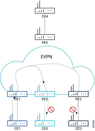
EVPN E-Tree for EVPN E-LAN

This chapter guides you on implementing EVPN E-Tree to securely segregate network traffic between root and leaf sites. Learn supported scenarios, feature highlights, and configuration steps to enhance security and optimize network performance.

EVPN E-Tree

An EVPN E-Tree is a network architecture that

  • segregates traffic to prevent direct communication between remote sites

  • reduces network congestion, and

  • minimizes the surface area vulnerable to attacks.

Table 1. Feature History Table

Feature Name

Release Information

Feature Description

EVPN E-Tree (Scenario 2)

Release 25.3.1

Introduced in this release on: Centralized Systems (8400 [ASIC: K100]) (select variants only*)

*This feature is now supported on the Cisco 8404-SYS-D routers.

EVPN E-Tree (Scenario 1a)

Release 25.3.1

Introduced in this release on: Centralized Systems (8400 [ASIC: K100]) (select variants only*)

*This feature is now supported on the Cisco 8404-SYS-D routers.

EVPN E-Tree (Scenario 2)

Release 24.4.1

Introduced in this release on: Fixed Systems (8700 [ASIC: P100])(select variants only*)

* The EVPN E-Tree (Scenario 2) functionality is now extended to the Cisco 8712-MOD-M routers.

EVPN E-Tree (Scenario 1a)

Release 24.4.1

Introduced in this release on: Fixed Systems (8700 [ASIC: P100])(select variants only*)

* The EVPN E-Tree (Scenario 1a) functionality is now extended to the Cisco 8712-MOD-M routers.

EVPN E-Tree (Scenario 2)

Release 24.3.1

Introduced in this release on: Fixed Systems (8200 [ASIC: P100], 8700 [ASIC: P100])(select variants only*); Modular Systems (8800 [LC ASIC: P100])(select variants only*)

; Modular Systems (8800 [LC ASIC: P100])(select variants only*)

* The EVPN E-Tree (Scenario 2) functionality is now extended to:

  • 8212-48FH-M

  • 8711-32FH-M

  • 88-LC1-52Y8H-EM

  • 88-LC1-12TH24FH-E

EVPN E-Tree (Scenario 1a)

Release 24.3.1

Introduced in this release on: Fixed Systems (8200 [ASIC: P100], 8700 [ASIC: P100])(select variants only*); Modular Systems (8800 [LC ASIC: P100])(select variants only*)

* The EVPN E-Tree (Scenario 1a) functionality is now extended to:

  • 8212-48FH-M

  • 8711-32FH-M

  • 88-LC1-52Y8H-EM

  • 88-LC1-12TH24FH-E

EVPN E-Tree (Scenario 2)

Release 24.2.11

Introduced in this release on: Modular Systems (8800 [LC ASIC: P100]) (select variants only*)

We now enable a PE device to have both root and leaf sites for a given EVI, which increases the granularity of leaf designation from the entire bridge to AC bridge ports; ACs under a bridge may be root or leaf.

* This feature is supported on routers with the 88-LC1-36EH line cards.

EVPN E-Tree (Scenario 1a)

Release 24.2.11

Introduced in this release on: Modular Systems (8800 [LC ASIC: P100]) (select variants only*)

We now support EVPN E-Tree with route-targets (RT) constraints using two RTs per EVI. This feature prevents L2 communication between the ACs of two or more leafs.

* This functinality is now supported on routers with the 88-LC1-36EH line cards.

EVPN E-Tree

Release 7.11.1

We now enable efficient forwarding of ethernet traffic in a tree-like topology where a root PE router broadcasts or multicasts traffic to all the leaf PE routers while the leaf PE routers only forward traffic destined for the respective customer sites connected to them.

This feature is supported only on Q200-based line cards.

The feature introduces the etree rt-leaf command.

Benefits of EVPN E-Tree

EVPN E-Tree provides several benefits that enhance network segmentation and security. These benefits include:

  • Enabling hierarchical traffic segregation by defining root and leaf nodes, which restricts communication between leaf nodes while allowing communication between root and leaf nodes.

  • Reducing unnecessary traffic flooding across the EVPN E-LAN by limiting leaf-to-leaf communication.

  • Enhancing security by preventing direct communication between remote sites or leaf nodes.

  • Improving network efficiency and scalability by controlling traffic flows and minimizing broadcast domains.

  • Supporting diverse enterprise and service provider networking scenarios that require controlled multi-point connectivity with traffic isolation.

How EVPN E-Tree service works

Summary

The key components involved in the EVPN E-Tree service are:

  • Root node (PE4): Acts as the central communication hub within the service provider’s network. It connects to all leaf nodes and manages traffic forwarding.

  • Leaf nodes (PE1, PE2, PE3): Represent customer sites or remote locations. They communicate only with the root node and do not forward traffic to other leaf nodes.

  • EVPN protocol: Enables dynamic learning of MAC addresses and supports efficient communication between root and leaf nodes.

The EVPN E-Tree process ensures that leaf nodes communicate only with the root node, preventing direct leaf-to-leaf traffic to enhance network isolation and reduce congestion. Dynamic MAC address learning through EVPN supports efficient traffic forwarding between the root and leaf nodes.

Workflow

These stages describe how EVPN E-Tree service works.

  1. ACs are defined as either root or leaf nodes. If a PE is not configured as a leaf, it defaults to root.
  2. The root node establishes connections with all leaf nodes, serving as the central point of communication.
  3. Leaf nodes send and receive traffic exclusively to and from the root node.
  4. The root node forwards traffic to all leaf nodes, ensuring communication is maintained without direct leaf-to-leaf traffic.
  5. Direct communication between leaf nodes is restricted to prevent unnecessary traffic and enhance network isolation.
  6. EVPN facilitates dynamic MAC address learning across the network, enabling flexible and efficient communication between root and leaf nodes.

Result

This process ensures hierarchical traffic segregation, maintaining communication between the root and leaf nodes while isolating leaf nodes from each other. It reduces unnecessary traffic, enhances security, and improves network efficiency.

E-Tree implementation scenarios

You can implement E-Tree using these scenarios; however, only scenario 1a and scenario 2 are supported:

  • Scenario 1: All ACs at a particular PE device for a given Ethernet VPN instance (EVI) or bridge domain (BD) are either root or leaf sites. In this scenario, all traffic for an EVI from a PE in the network originates from either a root or a leaf site. You have two configuration options:

    • Scenario 1a: Configure E-Tree with route-target (RT) constraints using two RTs per EVI.

    • Scenario 1b: Configure E-Tree without RT constraints by using the E-Tree leaf label.

  • Scenario 2: Configure a PE device to have both root and leaf sites for a given EVI.

E-Tree scenario 1a

EVPN E-Tree using route-target (RT) constraints allows you to configure BGP RT import and export policies for each AC. This configuration defines the communication pattern between root and leaf nodes within a BD. Layer 2 L2 traffic can flow only between root and leaf nodes—either from root to leaf or leaf to root—for a given BD. Direct L2 communication between leaf ACs is prevented, ensuring traffic isolation among leaf sites. Each EVI uses two distinct BGP RTs: one set associated with root ACs and another set associated with leaf ACs. This separation enforces the communication restrictions and maintains the E-Tree service topology.

BGP import and export policies for EVPN EVI instances

In EVPN EVI instances, BGP import and export policies govern the distribution of RTs to control Layer 2 communication between root and leaf PE devices.

  • Root PE behavior:

    • Exports its ROOT-RT using the BGP export policy.

    • Imports other ROOT-RTs from corresponding root PEs for the same EVI.

      This aspect is essential in scenarios with multiple roots for a BD and EVPN EVI, such as multihome active-active, port-active, and single-active modes.

    • Imports LEAF-RT through the BGP import policy. This allows the root PE to learn all remote L2 MAC addresses advertised by leaf PEs through EVPN RT2.

  • Leaf PE behavior:

    • Exports its LEAF-RT using the BGP export policy, and informs the root PE of the reachability of its directly connected L2 endpoints through EVPN RT2.

    • Imports ROOT-RT using the BGP import policy, which enables the leaf PE to discover L2 endpoints reachable through the root PE’s AC under the EVPN EVI instance.

    • Must not import LEAF-RT to prevent L2 communication between leaf PEs.

  • General policy application:

    • These BGP import and export policies apply to all EVPN RTs, including RT2 advertisements, ensuring proper isolation and communication paths within the E-Tree topology.

      This policy framework enforces the E-Tree service model by allowing L2 traffic only between root and leaf nodes, preventing direct leaf-to-leaf communication, and supporting multi-root scenarios for enhanced redundancy and scalability.

MAC address learning in EVPN E-Tree scenario 1a

  • L2 MAC addresses are learned on the AC of a specific BD on a leaf PE device as type LOCAL.

  • The leaf PE advertises the learned MAC address to the root PE as an EVPN route target 2 (RT2).

  • On the remote root PE, the MAC address entry is replicated in the MAC table with the learning type L2VPN.

  • The root PE associates the MAC entry with the MPLS label of its BGP peer that advertises RT2 to the root PE node.

  • Similarly, L2 MAC addresses learned on the AC of a BD on the root PE are marked as type LOCAL.

  • The root PE advertises these MAC addresses to peer root or leaf PEs as EVPN RT2.

  • On the remote root or leaf PE, the MAC table replicates the MAC entry with learning type L2VPN and associates it with the MPLS label of the BGP peer advertising RT2.

  • For root PEs, the MAC table of a peer root node synchronizes the replicated MAC entry with learning type L2VPN for the same Ethernet Segment Identifier (ESI) and uses the same AC as the next hop.

  • This synchronization prevents flooding and duplication of known unicast traffic, ensuring efficient MAC address learning and forwarding within the EVPN E-Tree topology.

Configure EVPN E-Tree scenario 1a

Configure EVPN E-Tree with route-target constraints on a PE device to enable root-to-leaf communication while isolating leaf-to-leaf traffic.

EVPN E-Tree Scenario 1a uses BGP route-target import and export policies to define ACs as root or leaf nodes within a BD and EVI. This configuration supports dynamic MAC learning and traffic filtering between root and leaf sites.

Procedure

Step 1

Configure the bridge domain.

Example:
Router# configure
Router(config)# l2vpn
Router(config-l2vpn)# bridge group BG1
Router(config-l2vpn-bg)# bridge-domain BD1
Router(config-l2vpn-bg-bd)# interface Bundle-Ether700.305
Router (config-l2vpn-bg-bd-ac)# exit
Router(config-l2vpn-bg-bd)# interface Bundle-Ether720.305
Router (config-l2vpn-bg-bd-ac)# exit
Router (config-l2vpn-bg-bd)# evi 305
Router (config-l2vpn-bg-bd-evi)# commit

Step 2

Configure attachment circuits.

Example:
Router# configure
Router(config)# interface Bundle-Ether700.305 l2transport
Router(config-l2vpn-subif)# encapsulation dot1q 305
Router(config-l2vpn-subif)# rewrite ingress tag pop 1 symmetric
Router(config-l2vpn-subif)# exit
Router(config-l2vpn)# exit
Router(config)# interface Bundle-Ether720.305 l2transport
Router(config-l2vpn-subif)# encapsulation dot1q 305
Router(config-l2vpn-subif)# rewrite ingress tag pop 1 symmetric
Router(config-l2vpn-subif)# commit

Step 3

Configure the EVPN EVI.

Example:
Router# configure
Router(config)# evpn
Router(config-evpn)# evi 305
Router(config-evpn-instance)# bgp
Router(config-evpn-instance-bgp)# route-target import 1001:305>>  Route target of leaf
Router(config-evpn-instance-bgp)# route-target export 1001:5305>> Route target of root
Router(config-evpn-instance-bgp)# exit
Router(config-evpn-instance)# exit
Router(config-evpn-instance)# etree
Router(config-evpn-instance-etree)# rt-leaf
Router(config-evpn-instance-etree)# exit
Router(config-evpn-instance)# control-word-disable 
Router(config-evpn-instance)# advertise-mac 
Router(config-evpn-instance-mac)# commit

Step 4

Configure bundle Ethernet interfaces.

Example:
Router# configure
Router(config)# interface Bundle-Ether700
Router(config-if)# lacp system mac 00aa.aabb.1010
Router(config-if)# lacp switchover suppress-flaps 300
Router(config-if)# lacp cisco enable link-order signaled
Router(config-if)# bundle wait-while 100 
Router(config-if)# exit
Router(config)# interface Bundle-Ether720
Router(config-if)# lacp system mac 00aa.aabb.1212
Router(config-if)# lacp switchover suppress-flaps 300
Router(config-if)# lacp cisco enable link-order signaled
Router(config-if)# bundle wait-while 100 
Router(config-if)# commit

Step 5

Configure EVPN interfaces.

Example:
Router(config)# evpn
Router(config-evpn)# interface Bundle-Ether700
Router(config-evpn-ac)# ethernet-segment
Router(config-evpn-ac-es)# identifier type 0 00.00.00.00.00.00.00.00.00
Router(config-evpn-ac-es)# bgp route-target 0000.0000.0001
Router(config-evpn-ac-es)# exit
Router(config-evpn-ac)# exit
Router(config-evpn)# exit
Router(config-evpn)# interface Bundle-Ether720
Router(config-evpn-ac)# ethernet-segment
Router(config-evpn-ac-es)# identifier type 0 00.00.00.00.00.00.00.00.00
Router(config-evpn-ac-es)# bgp route-target 0000.0000.0020
Router(config-evpn-ac-es)# commit

Step 6

Running configuration of EVPN E-Tree scenario 1a.

Example:
l2vpn
 bridge group BG1
  bridge-domain BD1
   interface Bundle-Ether700.305
   !
   interface Bundle-Ether720.305
    
   !
   evi 305
   !
  !
 !
interface Bundle-Ether700.305 l2transport
 encapsulation dot1q 305
 rewrite ingress tag pop 1 symmetric
!
interface Bundle-Ether720.305 l2transport
 encapsulation dot1q 305
 rewrite ingress tag pop 1 symmetric
!
evpn
 evi 305
  bgp
   route-target import 1001:305
   route-target export 1001:5305
  !
  etree
   rt-leaf
  !
  control-word-disable
  advertise-mac
  !
 !
!
interface Bundle-Ether700
 lacp system mac 00aa.aabb.1010
 lacp switchover suppress-flaps 300
 lacp cisco enable link-order signaled
 bundle wait-while 100
!
interface Bundle-Ether720
 lacp system mac 00aa.aabb.1212
 lacp switchover suppress-flaps 300
 lacp cisco enable link-order signaled
 bundle wait-while 100
!
evpn
 interface Bundle-Ether700
  ethernet-segment
   identifier type 0 00.00.00.00.00.00.00.00.00
   bgp route-target 0000.0000.0001
  !
 !
!
evpn
 interface Bundle-Ether720
  ethernet-segment
   identifier type 0 00.00.00.00.00.00.00.00.00
   bgp route-target 0000.0000.0020
  !
 !
!

Step 7

Use show l2route evpn mac all command to verify the EVPN E-Tree scenario 1a configuration.

The single-homing PE device only knows about its local L2 MAC addresses and the MAC addresses learned on the root node. The leaf single-homing PE device does not know any other MAC addresses learned on other leaf PE nodes. Each leaf is completely isolated from other leaf PEs in terms of their knowledge of MAC addresses learned from each other.

Example:

Router$ show l2route evpn mac all  
Topo ID  Mac Address    Producer    Next Hop(s)                             
-------- -------------- ----------- ----------------------------------------
200      0011.0100.0001 L2VPN       30579/I/ME, N/A                         
200      0011.0100.0002 L2VPN       30579/I/ME, N/A                         
200      0011.0100.0003 L2VPN       30579/I/ME, N/A                         
200      0011.0100.0004 L2VPN       30579/I/ME, N/A                         
200      0011.0100.0005 L2VPN       30579/I/ME, N/A                         
200      0012.0100.0001 LOCAL       Bundle-Ether700.305, N/A                
200      0012.0100.0002 LOCAL       Bundle-Ether700.305, N/A                
200      0012.0100.0003 LOCAL       Bundle-Ether700.305, N/A                
200      0012.0100.0004 LOCAL       Bundle-Ether700.305, N/A                
200      0012.0100.0005 LOCAL       Bundle-Ether700.305, N/A                

The PE device is configured for EVPN E-Tree scenario 1a, enabling root-to-leaf Layer 2 communication with isolation between leaf nodes. The device learns local MAC addresses and those learned on the root node, ensuring proper MAC address distribution and traffic filtering.

E-Tree scenario 2

Customer sites represented by ACs can be designated as either root or leaf nodes. For a given EVI, a PE device may receive traffic from both root and leaf ACs originating from a remote node. An EVI can be associated with both root and leaf sites simultaneously. If an AC is not explicitly configured as a leaf in the E-Tree topology, it defaults to being a root.

A PE device supports having both root and leaf sites within the same EVI. This scenario provides finer granularity by allowing root or leaf designation at the individual AC level, as opposed to scenario 1 where the designation is at the bridge domain level. Consequently, traffic for an EVI from a PE can originate from either root or leaf sites, enabling flexible and granular traffic segregation within the network.

Unicast traffic behavior in EVPN E-Tree scenario 2

  • Remote PE devices perform ingress filtering to avoid unnecessary traffic traversing the core network only to be filtered at the egress PE.

  • Each PE marks MAC addresses to indicate whether they are associated with a root or a leaf node.

  • MAC address advertisements from leaf sites include a leaf-indication flag within an extended community attribute; routes lacking this flag originate from root sites.

  • When remote PEs program MAC addresses with the leaf-indication flag, they cross-check the originating AC. If the AC is also a leaf, packets are not forwarded, preventing leaf-to-leaf traffic.

  • The solution supports E-Tree extended community type 0x06 (EVPN) with sub-type 0x05 for leaf-indication on both known unicast and BUM traffic.

  • Unknown unicast suppression should be enabled on EVIs connected to both root and leaf sites. This prevents unknown unicast traffic arriving at an EVI from being flooded to ACs, effectively eliminating leaf-to-leaf traffic during bridge domain MAC flush events.

  • MAC addresses advertise the local ESI and do not include a leaf indicator when originating from root nodes.

  • During processing of root synchronization routes, the root or leaf status is evaluated at the individual AC level rather than the entire bridge domain. If a root MAC with a matching local ESI is received but the corresponding AC is configured as a leaf, a syslog message is generated to indicate a misconfiguration.

BUM traffic behavior in EVPN E-Tree scenario 2

  • PE devices perform egress filtering on BUM traffic. BUM traffic originating from leaf sites is filtered at the egress PE if the destination is also a leaf, preventing leaf-to-leaf BUM traffic.

  • A PE with leaf sites assigns a leaf label and advertises this label to remote PEs through an Ethernet Segment/EVPN Auto-Discovery (ES/EAD) route with ESI set to 0, including the E-TREE extended community.

  • BUM traffic handling based on AC type and homing:

    • Single-homed leaf AC: BUM traffic is tagged with the destination ETREE leaf label.

    • Single-homed root AC: BUM traffic is not tagged with any ESI or ETREE leaf label.

    • Multi-homed leaf AC: BUM traffic is tagged with the destination ETREE leaf label.

    • Multi-homed root AC: BUM traffic is tagged with the ESI label.

  • The ingress PE tags MPLS frames originating from leaf sites with the ETREE leaf label. This label enables the egress PE to perform filtering based on native EVPN ESI label, ensuring proper BUM traffic segregation.

  • To prevent intra-PE forwarding between leaf sites, all leaf ACs within a bridge domain are placed in a single split-horizon group, effectively isolating leaf-to-leaf BUM traffic within the same PE.

Configure EVPN E-Tree scenario 2

Configure EVPN E-Tree on a PE device to establish root and leaf bridge domains for Ethernet VPN services.

This task applies when you need to set up EVPN E-Tree scenario 2 on a PE device, involving bridge domain configuration, E-Tree interface roles, and EVI setup.

Procedure

Step 1

Configure the bridge domain.

Example:

Router# configure
Router(config)# l2vpn
Router(config-l2vpn)# bridge group bg1
Router(config-l2vpn-bg)# bridge-domain bd_1

Step 2

Configure E-Tree interfaces.

Example:
Router(config-l2vpn-bg-bd)# interface Bundle-Ether400
Router(config-l2vpn-bg-bd-ac)# exit
Router(config-l2vpn-bg-bd)# # interface Bundle-Ether401.1001
Router(config-l2vpn-bg-bd-ac)# etree
Router(config-l2vpn-bg-bd-ac-etree)# leaf

Step 3

Configure the EVI.

Example:
Router(config-l2vpn-bg-bd)# evi 200
Router(config-l2vpn-bg-bd-evi)# commit

Step 4

Running configuration of EVPN E-Tree scenario 2.

Example:

/* Configuration for root and leaf */

l2vpn
 bridge group bg1
  bridge-domain bd_1
   interface Bundle-Ether400.1
   !
   interface Bundle-Ether401.1001
   !
   interface Bundle-Ether4701.2001
   !
   etree
    leaf
   !
   evi 200
   !
  !
 !

The PE device is configured with EVPN E-Tree scenario 2, establishing root and leaf interfaces within the specified bridge domain and associating them with the EVI.