EVPN MPLS Multihoming

This chapter provides an overview of EVPN MPLS multihoming modes, including single-active, all-active, port-active, and single-flow-active configurations for both E-LAN and E-Line services. Users can learn about key concepts, benefits, use cases, and step-by-step configuration procedures for deploying robust and redundant EVPN MPLS multihoming in their networks.

EVPN MPLS multihoming modes

EVPN MPLS multihoming modes are redundancy techniques in EVPN deployments that

  • connect a customer edge device to multiple provider edge devices

  • provide redundant connectivity for enhanced reliability, and

  • ensure uninterrupted traffic flow during network failures.

Modes of EVPN multihoming

These multihoming modes are supported:

  • Single-active: Only one PE device in the group attached to the Ethernet segment forwards traffic to and from that segment. This mode prevents loops by allowing a single active forwarder.

  • All-active: All PEs connected to the Ethernet segment are permitted to forward traffic simultaneously. This mode enables load sharing and active-active redundancy.

  • Port-active: Traffic is sent and received only by the PE that is in active mode on a specific port or interface. This mode supports single-active redundancy with load balancing at the port or interface level.

  • Single-flow-active: The PE that first advertises a host MAC address in a VLAN forwards traffic for that specific flow. This mode optimizes forwarding by directing each flow through a single active PE.

EVPN MPLS multihoming mode services

EVPN MPLS multihoming supports both E-LAN and E-LINE services.

This table compares the key features and use cases of EVPN E-LAN and E-LINE services.

Table 1. EVPN E-LAN and E-LINE services

Feature

EVPN E-LAN

EVPN E-Line

Connectivity type

Multipoint-to-Multipoint

Point-to-Point

Typical use cases

Multi-site connectivity, interconnecting multiple locations

Data center interconnects, connecting two sites

MAC address learning

Across all endpoints in the E-LAN

Limited to two endpoints

Supported modes

  • All-active

  • Single-active

  • Port-active

  • Single flow-active

  • All-active

  • Single-active

  • Port-active

While the configuration specifics differ between E-LAN and E-LINE services, their conceptual framework remains identical. Therefore, for conceptual understanding, the E-LAN documentation serves as the primary reference point for both services.

EVPN E-LAN single-active multihoming mode

EVPN E-LAN single-active multihoming mode is a network redundancy method that

  • enables PE nodes locally connected to an Ethernet segment to load balance traffic to and from the segment based on an EVI

  • ensures that within an EVI, only one PE forwards traffic to and from the Ethernet segment, and

  • supports efficient use of network resources by managing active forwarding paths.

Table 2. Feature History Table

Feature Name

Release Information

Feature Description

EVPN E-LAN single-active multihoming mode

Release 24.4.1

Introduced in this release on: Fixed Systems (8700) (select variants only*)

* The EVPN E-LAN single-active multi-homing functionality is now extended to the Cisco 8712-MOD-M routers.

EVPN E-LAN single-active multihoming mode

Release 24.3.1

Introduced in this release on: Fixed Systems (8200 [ASIC: P100], 8700 [ASIC: P100])(select variants only*); Modular Systems (8800 [LC ASIC: P100])(select variants only*)

*The EVPN E-LAN single-active multi-homing functionality is now extended to:

  • 8212-48FH-M

  • 8711-32FH-M

  • 88-LC1-52Y8H-EM

  • 88-LC1-12TH24FH-E

EVPN E-LAN single-active multihoming mode

Release 24.2.11

Introduced in this release on: Modular Systems (8800 [LC ASIC: P100]) (select variants only*)

The single-active multi-homing mode offers redundant connectivity on a single link at a time with failover to the second link in case the active link fails. In this mode, only a single PE among a group of PEs attached to an Ethernet segment forwards traffic to and from that Ethernet Segment.

* This feature is supported only on routers with the 88-LC1-36EH line cards.

EVPN E-LAN single-active multihoming mode for redundant connectivity

EVPN E-LAN single-active multihoming mode provides network redundancy in EVPN environments, especially in ring topologies:

  • Only one PE device, the active PE, handles traffic forwarding and reception for an Ethernet segment at a time, preventing network loops.

  • When the active PE's link fails, traffic switches to a standby PE. During switchover, the standby PE learns the MAC addresses, which can cause a brief interruption.

  • The standby PE quickly learns MAC addresses from the failed path, supporting rapid convergence and minimizing traffic loss.

  • A CE device can connect to multiple PEs for redundancy. The first PE to advertise a host’s MAC address in a VLAN becomes the active forwarder for that MAC.

  • This mode also enables load balancing for traffic to and from the Ethernet segment, based on the EVI.

Benefits of single-active multihoming mode

Single-active multihoming mode offers several key advantages for network management and service provision:

  • Redundant connectivity: Provides a backup link that automatically takes over if the active link fails, ensuring continuous service availability.

  • Simplified traffic management: Directs traffic to a single uplink, simplifying the monitoring and management of data flows.

  • Enhanced network control: Allows for precise control over bandwidth restrictions and data usage accounting, which is beneficial for implementing policing and metering.

  • Billing flexibility: Facilitates accurate billing for business customers by integrating with internal billing systems, ensuring proper account management.

  • High availability: Maintains a reliable connection by utilizing redundant paths, enhancing overall network resilience.

How EVPN E-LAN single-active multihoming mode works

Summary

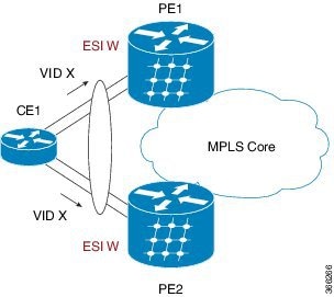
The EVPN E-LAN single-active multihoming process involves a network topology where a CE1 device is multihomed to two provider edge devices,PE1 and PE2, connected through an MPLS core to PE3. This process ensures efficient traffic flow and redundancy.

The key components involved in the process are:

  • CE1: A customer edge device multihomed to PE1 and PE2.

  • PE1 and PE2: Provider edge devices connected to CE1 and PE3, responsible for advertising routes and managing traffic flow.

  • PE3: A provider edge device connected to CE2 through an Ethernet interface bundle.

  • CE2: A customer edge device connected to PE3.

Workflow

The process involves the following stages:

  1. Route advertisement:

    • PE1 and PE2 advertise Type 4 routes to elect the designated forwarder (DF). PE1 is elected as the DF, while PE2 becomes the non-DF.

  2. Traffic management:

    • CE1 sends an ARP broadcast request to both PE1 and PE2.

    • PE1, as the DF, forwards the ARP request from CE1.

    • PE2, being the non-DF, drops the traffic from CE1.

  3. Traffic flow:

    • All traffic is sent through PE1, with PE2 acting as a standby device.

    • PE1 advertises MAC routes to PE3.

    • PE3 sends and receives traffic through PE1 and forwards it to CE2 over the Ethernet interface bundle.

  4. Redundancy management:

    • In case of a link failure where PE1 goes down, PE2 becomes active to maintain the traffic flow.

The EVPN E-LAN single-active multihoming process ensures efficient and reliable traffic flow while providing redundancy. When the active link (PE1) fails, the router automatically switches to the standby link (PE2) to maintain network connectivity.

Configure EVPN single-active multihoming mode

Set up EVPN single-active multihoming on PE routers for efficient network redundancy and load balancing.

This task involves configuring BGP sessions and MPLS LDP, setting up EVPN EVI parameters, and enabling single-active mode on PE routers.

Perform the following configuration on PE1, PE2, and PE3.

  1. Configure BGP session and MPLS Label Distribution Protocol (LDP) to enable EVPN.

  2. Configure bridge domain, EVI, and advertisement of MAC routes.

  3. Enter the bundle interface mode and configure the Ethernet segment identifier (ESI) for the interface.

  4. Ensure that you configure the same ESI on all the PEs.

  5. Enable single-active mode by using the load-balancing-mode single-active command.

Procedure


Step 1

Configure BGP session and MPLS LDP to enable EVPN on PE routers.

Example:

PE1 configuration.

Router(config)# router bgp 100
Router(config-bgp)# bgp router-id 54.54.54.54
Router(config-bgp)# address-family l2vpn evpn
Router(config-bgp)# neighbor 51.51.51.51
Router(config-bgp-nbr)# remote-as 100
Router(config-bgp-nbr)# update-source Loopback 0
Router(config-bgp-nbr)# address-family l2vpn evpn
Router(config-bgp)# neighbor 55.55.55.55
Router(config-bgp-nbr)# remote-as 100
Router(config-bgp-nbr)# update-source Loopback 0
Router(config-bgp-nbr)# address-family l2vpn evpn

Configure MPLS LDP.

Router(config)# mpls ldp
Router(config-ldp)# router-id 55.55.55.55
Router(config-ldp)# interface FourHundredGigE0/0/0/2

PE2 configuration.

Router(config)# router bgp 100
Router(config-bgp)# bgp router-id 55.55.55.55
Router(config-bgp)# address-family l2vpn evpn
Router(config-bgp)# neighbor 51.51.51.51
Router(config-bgp-nbr)# remote-as 100
Router(config-bgp-nbr)# update-source Loopback 0
Router(config-bgp-nbr)# address-family l2vpn evpn
Router(config-bgp)# neighbor 54.54.54.54
Router(config-bgp-nbr)# remote-as 100
Router(config-bgp-nbr)# update-source Loopback 0
Router(config-bgp-nbr)# address-family l2vpn evpn

Configure MPLS LDP.

Router(config)# mpls ldp
Router(config-ldp)# router-id 55.55.55.55
Router(config-ldp)# interface FourHundredGigE0/0/0/2

PE3 configuration.

Router(config)# router bgp 100
Router(config-bgp)# bgp router-id 51.51.51.51
Router(config-bgp)# address-family l2vpn evpn
Router(config-bgp)# neighbor 54.54.54.54
Router(config-bgp-nbr)# remote-as 100
Router(config-bgp-nbr)# update-source Loopback 0
Router(config-bgp-nbr)# address-family l2vpn evpn
Router(config-bgp)# neighbor 55.55.55.55
Router(config-bgp-nbr)# remote-as 100
Router(config-bgp-nbr)# update-source Loopback 0
Router(config-bgp-nbr)# address-family l2vpn evpn

Configure MPLS LDP.

Router(config)# mpls ldp
Router(config-ldp)# router-id 51.51.51.51
Router(config-ldp)# interface FourHundredGigE0/0/0/2

Step 2

Configure bridge domain, EVI, and advertise MAC routes.

Example:

Router(config)# l2vpn 
Router(config-l2vpn)# bridge group bg1
Router(config-l2vpn-bg)# bridge-domain bd1
Router(config-l2vpn-bg-bd)# interface Bundle-Ether1.1
Router(config-l2vpn-bg-bd-ac)# evi 1
Router(config-l2vpn-bg-bd-ac)# root
Router(config)# l2vpn 
Router(config-l2vpn)# bridge group bg2
Router(config-l2vpn-bg)# bridge-domain bd2
Router(config-l2vpn-bg-bd)# interface Bundle-Ether1.2
Router(config-l2vpn-bg-bd-ac)# evi 2

Configure EVPN EVI parameters and advertise MAC routes.

Router(config)# evpn
Router(config-evpn)# evi 1
Router(config-evpn-evi)# advertise-mac
Router(config-evpn-evi)# exit
Router(config-evpn)# evi 2
Router(config-evpn-evi)# advertise-mac

Step 3

Enter the bundle interface mode and configure the same ESI on all the PE routers.

Example:

Router(config)# evpn
Router(config-evpn)# interface Bundle-Ether1
Router(config-evpn-ac)# ethernet-segment
Router(config-evpn-ac-es)# identifier type 0 40.00.00.00.00.00.00.00.01

Step 4

Enable single-active mode.

Example:

Router(config-evpn-ac-es)# load-balancing-mode single-active
Router(config-evpn-ac-es)# commit

Step 5

Running configuration of EVPN single-active multihoming mode.

Example:


/* PE1 Configuration */
router bgp 100
 bgp router-id 54.54.54.54
 address-family l2vpn evpn
 !
 neighbor 51.51.51.51
  remote-as 100
  update-source Loopback0
  address-family l2vpn evpn
  !
 !
 neighbor 55.55.55.55
  remote-as 100
  update-source Loopback0
  address-family l2vpn evpn
  !
 !
!
mpls ldp
 router-id 54.54.54.54
 interface FourHundredGigE0/0/0/2
 !
!

/* PE2 Configuration */
router bgp 100
 bgp router-id 55.55.55.55
 address-family l2vpn evpn
 !
 neighbor 51.51.51.51
  remote-as 100
  update-source Loopback0
  address-family l2vpn evpn
  !
 !
 neighbor 54.54.54.54
  remote-as 100
  update-source Loopback0
  address-family l2vpn evpn
  !
 !
!
mpls ldp
 router-id 55.55.55.55
 interface FourHundredGigE0/0/0/2
 !
!

/* PE3 Configuration */
router bgp 100
 bgp router-id 51.51.51.51
 address-family l2vpn evpn
 !
 neighbor 54.54.54.54
  remote-as 100
  update-source Loopback0
  address-family l2vpn evpn
  !
 !
 neighbor 55.55.55.55
  remote-as 100
  update-source Loopback0
  address-family l2vpn evpn
  !
 !
!
mpls ldp
 router-id 51.51.51.51
 interface FourHundredGigE0/0/0/3
 !
!

Configuration of bridge domain, EVI, and advertise MAC routes on all the PEs.


l2vpn
 bridge group bg1
  bridge-domain bd1
   interface Bundle-Ether1.1
   !
   evi 1
   !
  !
 !
 bridge group bg2
  bridge-domain bd2
   interface Bundle-Ether1.2
   !
   evi 2
   !
  !
 !
!
evpn
 evi 1
  advertise-mac
  !
 !
 evi 2
  advertise-mac
  !
 !
 interface Bundle-Ether1
  ethernet-segment
   identifier type 0 40.00.00.00.00.00.00.00.01
   load-balancing-mode single-active
  !
 !
!

Step 6

Use the show evpn ethernet-segment interface BE1 carving detail to verify that single-active mode is configured on PE1.

Example:

Router# show evpn ethernet-segment interface BE1 carving detail

Ethernet Segment Id      Interface                          Nexthops            
------------------------ ---------------------------------- --------------------
0040.0000.0000.0000.0001 BE1                                54.54.54.54
                                                            55.55.55.55
  ES to BGP Gates   : Ready
  ES to L2FIB Gates : Ready
  Main port         :
     Interface name : Bundle-Ether1
     Interface MAC  : 008d.9c38.7205
     IfHandle       : 0x0f00003c
     State          : Up
     Redundancy     : Not Defined
  ESI ID            : 1
  ESI type          : 0
     Value          : 0040.0000.0000.0000.0001
  ES Import RT      : 4000.0000.0000 (from ESI)
  Topology          :
     Operational    : MH, Single-active
     Configured     : Single-active (AApS)
  Service Carving   : Auto-selection
     Multicast      : Disabled
  Convergence       : 
  Peering Details   : 2 Nexthops
     54.54.54.54 [MOD:P:00:T]
     55.55.55.55 [MOD:P:00:T]
  Service Carving Synchronization:
     Mode           : NONE
     Peer Updates   :
             54.54.54.54 [SCT: N/A]
             55.55.55.55 [SCT: 2024-03-12 10:42:30.1710254]
  Service Carving Results:
     Forwarders     : 2
     Elected        : 1
            EVI E   :        2
     Not Elected    : 1
            EVI NE  :        1
  EVPN-VPWS Service Carving Results:
     Primary        : 0
     Backup         : 0
     Non-DF         : 0
  MAC Flush msg     : STP-TCN
  Peering timer     : 3 sec [not running]
  Recovery timer    : 30 sec [not running]
  Carving timer     : 0 sec [not running]
  Revert timer      : 0 sec [not running]
  HRW Reset timer   : 5 sec [not running]
  Local SHG label   : 24004
  Remote SHG labels : 1
              24004 : nexthop 55.55.55.55
  Access signal mode: Bundle OOS


The EVPN single-active multihoming configuration is applied across PE routers, ensuring optimized redundancy and load balancing.

Disabling MAC flush messages is particularly relevant in the context of EVPN single-active multihoming mode, as it helps prevent network disruptions at the CE by mitigating issues like BPDU guard triggers when configuring multihoming scenarios.


MAC flush message disablement

Disabling MAC flush messages is a configuration option that

  • prevents MAC flush messages from being sent for an Ethernet segment

  • addresses undesired behavior such as triggering BPDU guard at the CE, and

  • is implemented using the mac-flush-message disable command during the configuration of EVPN single-active multihoming on PE routers.

Disable MAC flush messages for EVPN single-active multihoming mode

Set up EVPN and L2VPN configurations to manage Ethernet segments effectively with MAC flush messages disabled.

This task is performed to configure EVPN and L2VPN settings on a router to handle Ethernet segments with specific identifiers and load balancing mode. It includes setting up bridge groups and domains, configuring interfaces, and ensuring MAC flush messages are disabled for the specified segments

Procedure

Step 1

Configure L2VPN.

Example:
Router(config)#l2vpn
Router(config-l2vpn)#bridge group 100
Router(config-l2vpn-bg)#bridge-domain 100
Router(config-l2vpn-bg-bd)#interface Bundle-Ether2.10
Router(config-l2vpn-bg-bd)#evi 100
Router(config-l2vpn-bg-bd-evi)#commit

Step 2

Configure EVPN single-active multihoming mode and disable MAC flush message.

Example:
Router(config)#evpn
Router(config-evpn)#evi 100 
Router(config-evpn-instance)#advertise-mac
Router(config-evpn-instance-mac)#exit
Router(config-evpn-instance)#exit
Router(config-evpn)#interface Bundle-Ether1
Router(config-evpn-ac)#ethernet-segment
Router(config-evpn-ac-es)#identifier type 0 36.37.00.00.00.00.00.11.00
Router(config-evpn-ac-es)#load-balancing-mode single-active
Router(config-evpn-ac-es)#exit
Router(config-evpn-ac)# mac-flush-message disable
Router(config-evpn-ac)# commit

Step 3

Running configuration.

Example:

l2vpn     
 bridge group 100
  bridge-domain 100
   interface Bundle-Ether1.10
   !      
   evi 100
   !      
  !       
 !        
!  
evpn
 evi 100  
  advertise-mac
  !   
 !        
 interface Bundle-Ether1
  ethernet-segment
   identifier type 0 36.37.00.00.00.00.00.11.00
   load-balancing-mode single-active
  !
  mac-flush-message disable 
  !       
 !        
!         

Step 4

Use the show evpn ethernet-segment detail command to verify the MAC flush message status.

Example:

Router#show evpn ethernet-segment detail

Legend:
  B   - No Forwarders EVPN-enabled,
  C   - Backbone Source MAC missing (PBB-EVPN),
  RT  - ES-Import Route Target missing,
  E   - ESI missing,
  H   - Interface handle missing,
  I   - Name (Interface or Virtual Access) missing,
  M   - Interface in Down state,
  O   - BGP End of Download missing,
  P   - Interface already Access Protected,
  Pf  - Interface forced single-homed,
  R   - BGP RID not received,
  S   - Interface in redundancy standby state,
  X   - ESI-extracted MAC Conflict
  SHG - No local split-horizon-group label allocated

Ethernet Segment Id      Interface                          Nexthops            
------------------------ ---------------------------------- --------------------
0036.3700.0000.0000.1100 BE1                                10.1.1.1
                                                            10.2.2.2
  ES to BGP Gates   : Ready
  ES to L2FIB Gates : Ready
  Main port         :
     Interface name : Bundle-Ether1
     Interface MAC  : 0008.3302.3208
     IfHandle       : 0x02000160
     State          : Up
     Redundancy     : Not Defined
  ESI type          : 0
     Value          : 36.3700.0000.0000.1100
  ES Import RT      : 3637.0000.0000 (from ESI)
  Source MAC        : 0000.0000.0000 (N/A)
  Topology          :
    Operational    : MH, Single-active
     Configured     : Single-active (AApS)
  Service Carving   : Auto-selection
     Multicast      : Disabled
  Convergence       : 
     Mobility-Flush : Count 0, Skip 0, Last n/a
  Peering Details   : 2 Nexthops
     10.1.1.1 [MOD:P:00]
     10.2.2.2 [MOD:P:00]
 Service Carving Results:
     Forwarders     : 1
     Elected        : 1
     Not Elected    : 0
  EVPN-VPWS Service Carving Results:
     Primary        : 0
     Backup         : 0
     Non-DF         : 0
  MAC Flush msg     : Disabled
  Peering timer     : 3 sec [not running]
  Recovery timer    : 30 sec [not running]
  Carving timer     : 0 sec [not running]
  Local SHG label   : 24007
  Remote SHG labels : 1
              24007 : nexthop 10.2.2.2
  Access signal mode: Bundle OOS (Default)

Check that the MAC flush message is disabled in the output.


EVPN E-LAN all-active multihoming mode

An EVPN E-LAN all-active multihoming mode is a networking model that

  • enables multiple simultaneous active connections from an EVPN to a single Ethernet LAN

  • allows all PE routers attached to a particular Ethernet segment to forward traffic to and from that Ethernet segment, and

  • provides redundancy and load balancing by allowing traffic distribution across all available links, enhancing network reliability and efficiency by utilizing all potential paths without requiring a failover mechanism.

Table 3. Feature History Table

Feature Name

Release Information

Feature Description

EVPN E-LAN all-active multihoming mode

Release 24.4.1

Introduced in this release on: Fixed Systems (8700) (select variants only*)

* The EVPN E-LAN all-active multi-homing functionality is now extended to the Cisco 8712-MOD-M routers.

E-LAN all-active multihoming mode

Release 24.3.1

Introduced in this release on: Fixed Systems (8200 [ASIC: P100], 8700 [ASIC: P100])(select variants only*); Modular Systems (8800 [LC ASIC: P100])(select variants only*)

* The EVPN E-LAN all-active multi-homing functionality is now extended to:

  • 8212-48FH-M

  • 8711-32FH-M

  • 88-LC1-52Y8H-EM

  • 88-LC1-12TH24FH-E

E-LAN all-active multihoming mode

Release 24.2.11

Introduced in this release on: Modular Systems (8800 [LC ASIC: P100]) (select variants only*)

The all-active multi-homing mode enables redundant network connectivity by allowing a CE device to connect to more than one PE device. In this mode, all the links actively forward the traffic.

* This feature is supported only on routers with the 88-LC1-36EH line cards.

Business connectivity challenges

Consider a scenario where the enterprise XYZ is operating in two different cities, with its headquarters (HQ) in Denver and a branch office in Dallas.

The business customer hosts all voice and video services in their active data center at HQ, Denver. The branch site in Dallas has minimal services for regional operations and might need to offload certain tasks to HQ. Additionally, the HQ site is used to update storage over a high-speed connection. Enterprise XYZ has approached the service provider for Layer 2 connectivity services, requiring direct L2 services for data center workloads at both HQ and the branch site.

The HQ in Denver is critical for the business, necessitating maximum throughput and high availability. The remote branch in Dallas can operate with a single uplink.

All-active multihoming as the ideal solution

To address these requirements, the service provider plans to deploy Layer 2 connectivity that seamlessly balances workloads across multiple sites while providing reliable and redundant connections with high availability. EVPN all-active multihoming mode is chosen as the solution for this scenario.

In all-active multihoming mode, both the PE devices attached to the Ethernet segment are allowed to receive and send traffic. This mode ensures redundant connectivity with no traffic disruption in the event of a network failure. It also offers high availability, efficient bandwidth utilization, and faster convergence, making it ideal for scenarios like HQ in Denver where maximum throughput and reliability are essential.

How EVPN E-LAN all-active multihoming works

Summary

The EVPN E-LAN all-active multihoming mode enables load balancing and redundancy by allowing multiple PE devices to forward traffic concurrently. PE devices use identical Ethernet Segment Identifiers (ESIs) and bundle interfaces to achieve this.

The key components involved in the process are:

  • CE1: Single bundles towards two EVPN PE devices, allowing connectivity to the MPLS core.

  • PE1 and PE2: Utilize identical ESIs and attach to the Ethernet segment using bundle interfaces, enabling simultaneous traffic forwarding within the same EVI.

  • MPLS core: The central network component that provides connectivity and routes traffic between PEs and other network entities.

Workflow

The process involves these stages:

  1. Configuration of CE1: CE1 is configured with single bundle interfaces directed towards both PE1 and PE2.

  2. ESI configuration on PEs: Both PE1 and PE2 are configured with identical ESIs, allowing them to recognize and manage the same Ethernet segment.

  3. Traffic forwarding: In this all-active mode, both PE1 and PE2 can concurrently forward traffic within the same EVI, providing load balancing and redundancy.

  4. Load balancing: Traffic is distributed across both PEs, leveraging the Active/Active per Flow (AApF) mechanism for optimal utilization of resources.

Result

The EVPN E-LAN all-active multihoming mode ensures efficient load balancing, increased redundancy, and robust connectivity within the MPLS network by enabling simultaneous traffic forwarding through multiple PEs.

Configure EVPN E-LAN all-active multihoming mode

Set up an EVPN E-LAN all-active multihoming mode on PE1 and PE2.

This task involves configuring BGP sessions, MPLS Label Distribution Protocol (LDP), and EVPN EVI parameters on both PE1 and PE2 to enable EVPN E-LAN all-active multihoming.

Before you begin

  • Ensure all equipment is powered on and accessible.

  • Verify network connectivity between PE1 and PE2.

Procedure


Step 1

Configure BGP session and MPLS LDP on PE1.

Example:

Configure BGP session on PE1.

Router(config)# router bgp 100
Router(config-bgp)# bgp router-id 54.54.54.54
Router(config-bgp)# address-family l2vpn evpn
Router(config-bgp)# neighbor 51.51.51.51
Router(config-bgp-nbr)# remote-as 100
Router(config-bgp-nbr)# update-source Loopback 0
Router(config-bgp-nbr)# address-family l2vpn evpn
Router(config-bgp)# neighbor 55.55.55.55
Router(config-bgp-nbr)# remote-as 100
Router(config-bgp-nbr)# update-source Loopback 0
Router(config-bgp-nbr)# address-family l2vpn evpn

Configure MPLS LDP on PE1.

Router(config)# mpls ldp
Router(config-ldp)# router-id 54.54.54.54
Router(config-ldp)# interface FourHundredGigE0/0/0/2

Step 2

Configure BGP session and MPLS LDP on PE2.

Example:

Configure BGP session on PE2.

Router(config)# router bgp 100
Router(config-bgp)# bgp router-id 55.55.55.55
Router(config-bgp)# address-family l2vpn evpn
Router(config-bgp)# neighbor 51.51.51.51
Router(config-bgp-nbr)# remote-as 100
Router(config-bgp-nbr)# update-source Loopback 0
Router(config-bgp-nbr)# address-family l2vpn evpn
Router(config-bgp)# neighbor 54.54.54.54
Router(config-bgp-nbr)# remote-as 100
Router(config-bgp-nbr)# update-source Loopback 0
Router(config-bgp-nbr)# address-family l2vpn evpn

Configure MPLS LDP on PE2.

Router(config)# mpls ldp
Router(config-ldp)# router-id 55.55.55.55
Router(config-ldp)# interface FourHundredGigE0/0/0/2

Step 3

Configure bridge domain and EVI on PE1 and PE2.

Example:

Router(config)# l2vpn 
Router(config-l2vpn)# bridge group bg1
Router(config-l2vpn-bg)# bridge-domain bd1
Router(config-l2vpn-bg-bd)# interface Bundle-Ether11.1
Router(config-l2vpn-bg-bd-ac)# evi 1
Router(config-l2vpn-bg-bd-ac)# root
Router(config)# l2vpn 
Router(config-l2vpn)# bridge group bg2
Router(config-l2vpn-bg)# bridge-domain bd2
Router(config-l2vpn-bg-bd)# interface Bundle-Ether11.2
Router(config-l2vpn-bg-bd-ac)# evi 2

Step 4

Configure EVPN EVI and advertise MAC routes on PE1 and PE2.

Example:

Router(config)# evpn
Router(config-evpn)# evi 1
Router(config-evpn-evi)# advertise-mac
Router(config-evpn-evi)# exit
Router(config-evpn)# evi 2
Router(config-evpn-evi)# advertise-mac

Step 5

Configure the same ESI on PE1 and PE2.

Example:

Router(config)# evpn
Router(config-evpn)# interface Bundle-Ether11
Router(config-evpn-ac)# ethernet-segment
Router(config-evpn-ac-es)# identifier type 0 40.00.00.00.00.00.00.00.01
Router(config-evpn-ac-es)# commit

Step 6

EVPN E-LAN all-active multihoming mode running configuration.

Example:


/* PE1 Configuration */
router bgp 100
 bgp router-id 54.54.54.54
 address-family l2vpn evpn
 !
 neighbor 51.51.51.51
  remote-as 100
  update-source Loopback0
  address-family l2vpn evpn
  !
 !
 neighbor 55.55.55.55
  remote-as 100
  update-source Loopback0
  address-family l2vpn evpn
  !
 !
!
mpls ldp
 router-id 54.54.54.54
 interface FourHundredGigE0/0/0/2
 !
!/* PE2 Configuration */
router bgp 100
 bgp router-id 55.55.55.55
 address-family l2vpn evpn
 !
 neighbor 51.51.51.51
  remote-as 100
  update-source Loopback0
  address-family l2vpn evpn
  !
 !
 neighbor 54.54.54.54
  remote-as 100
  update-source Loopback0
  address-family l2vpn evpn
  !
 !
!
mpls ldp
 router-id 55.55.55.55
 interface FourHundredGigE0/0/0/2
 !
!
/* Configuration on PE1 and PE2 */
l2vpn
 bridge group bg1
  bridge-domain bd1
   interface Bundle-Ether11.1
   !
   evi 1
   !
  !
 !
 bridge group bg2
  bridge-domain bd2
   interface Bundle-Ether11.2
   !
   evi 2
   !
  !
 !
!
evpn
 evi 1
  advertise-mac
  !
 !
 evi 2
  advertise-mac
  !
 !
 interface Bundle-Ether11
  ethernet-segment
   identifier type 0 40.00.00.00.00.00.00.00.01
  !
 !
!

Step 7

Use the show evpn ethernet-segment int Bundle-Ether 11 carving detail command to verify that EVPN all-active multihoming mode is configured on PE1 and PE2.

Example:


Router#show evpn ethernet-segment int Bundle-Ether 11 carving detail

Ethernet Segment Id      Interface                          Nexthops            
------------------------ ---------------------------------- --------------------
0040.0000.0000.0000.0001 BE11                                54.54.54.54
                                                             55.55.55.55
  ES to BGP Gates   : Ready
  ES to L2FIB Gates : Ready
  Main port         :
     Interface name : Bundle-Ether11
     Interface MAC  : 008d.9c38.7205
     IfHandle       : 0x0f00001c
     State          : Up
     Redundancy     : Not Defined
  ESI ID            : 1
  ESI type          : 0
     Value          : 0040.0000.0000.0000.0001
  ES Import RT      : 4000.0000.0000 (from ESI)
  Topology          :
     Operational    : MH, All-active
     Configured     : All-active (AApF) (default)
  Service Carving   : Auto-selection
     Multicast      : Disabled
  Convergence       : 
  Peering Details   : 2 Nexthops
     54.54.54.54 [MOD:P:00:T]
     55.55.55.55 [MOD:P:00:T]
  Service Carving Synchronization:
     Mode           : NONE
     Peer Updates   :
             54.54.54.54 [SCT: N/A]
             55.55.55.55 [SCT: N/A]
  Service Carving Results:
     Forwarders     : 2
     Elected        : 1
            EVI E   :        2
     Not Elected    : 1
            EVI NE  :        1
  EVPN-VPWS Service Carving Results:
     Primary        : 0
     Backup         : 0
     Non-DF         : 0
  MAC Flush msg     : STP-TCN
  Peering timer     : 3 sec [not running]
  Recovery timer    : 30 sec [not running]
  Carving timer     : 0 sec [not running]
  Revert timer      : 0 sec [not running]
  HRW Reset timer   : 5 sec [not running]
  Local SHG label   : 24004
  Remote SHG labels : 1
              24004 : nexthop 55.55.55.55
  Access signal mode: Bundle OOS
  

EVPN E-LAN port-active multihoming mode

An EVPN E-LAN port-active multihoming is a network model that

  • supports single-active redundancy load balancing at the port-level or interface-level

  • provides faster convergence during a link failure, and

  • enables protocol simplification by having only one physical port active at a given time.

Table 4. Feature History Table

Feature Name

Release Information

Feature Description

EVPN E-LAN port-active multihoming mode

Release 25.2.1

Introduced in this release on: Centralized Systems (8400 [ASIC: K100]) (select variants only*)

*This feature is now supported on the Cisco 8404-SYS-D routers.

EVPN E-LAN port-active multihoming mode

Release 24.4.1

Introduced in this release on: Fixed Systems (8200, 8700); Centralized Systems (8600); Modular Systems (8800 [LC ASIC: Q200])(select variants only*)

*The EVPN E-LAN port-active multi-homing mode is now extended to:

  • 8712-MOD-M

  • 8201-32FH

  • 8201-24H8FH

  • 8202-32FH-M

  • 8608

  • 88-LC0-34H14FH

  • 88-LC0-36FH

  • 88-LC0-36FH-M

EVPN E-LAN port-active multihoming mode

Release 24.3.1

Introduced in this release on: Fixed Systems (8200 [ASIC: P100], 8700 [ASIC: P100])(select variants only*); Modular Systems (8800 [LC ASIC: P100])(select variants only*)

*The EVPN E-LAN port-active multi-homing is now extended to:

  • 8212-48FH-M

  • 8711-32FH-M

  • 88-LC1-52Y8H-EM

  • 88-LC1-12TH24FH-E

EVPN E-LAN port-active multihoming mode

Release 24.2.11

Introduced in this release on: Modular Systems (8800 [LC ASIC: P100]) (select variants only*)

The port-active multi-homing mode enables single-active redundancy load balancing at the port-level or the interface-level. In this mode, one of the PEs remains active at the port-level.

* This feature is supported only on routers with the 88-LC1-36EH line cards.

Port-active mode for network traffic management

Port-active mode streamlines operations by providing a simpler alternative to ICCP-based MC-LAG solutions. This mode allows you to:

  • enable precise control over QoS features by ensuring only one PE device actively forwards traffic at a time

  • reduce complexity and operational overhead compared to multichassis approaches that rely on ICCP and LDP, and

  • improve overall traffic management efficiency by using selective port activation and a clear standb-active model.

Active and standby mode operation at port level

The EVPN E-LAN port-active mode enables one PE to be active and another to be standby on a per-port basis. Only the active PE sends and receives traffic, while the standby PE remains passive. The designated forwarder (DF) election mechanism ensures proper role assignment, supporting either modulo or HRW algorithms for per-port elections. By default, the modulo algorithm is used for per port DF election.

Benefits of EVPN E-LAN port-active multihoming

The benefits of this mode include protocol simplification, efficient traffic handling, improved QoS support, robust role assignment, and enhanced network stability, as demonstrated by:

  • Protocol simplification: Eliminates the need for ICCP, reducing protocol complexity and operational overhead.

  • Efficient traffic handling: Only the active PE port handles traffic, preventing duplication and ensuring clear traffic paths.

  • Improved QoS support: Facilitates QoS features that require a single active forwarding point per port.

  • Robust role assignment:Uses a Designated Forwarder (DF) election mechanism with either modulo or Highest Random Weight (HRW) algorithms to dynamically assign active and standby roles per port.

  • Enhanced network stability: By having a standby PE port ready to take over, it improves network resilience and failover capabilities.

This approach streamlines network design and operation while maintaining high availability and performance at the port level.

How EVPN E-LAN port-active multihoming mode works

Summary

The process of aggregating links in a multihomed topology involves managing traffic flow between customer edge and provider edge devices. The key components involved in the process are:

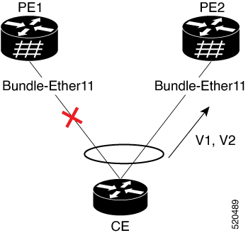
  • CE: Utilizes single link aggregation and connects to multiple provider edge devices.

  • PE1: Initially in standby mode; its interface is not forwarding traffic.

  • PE2: Initially in active mode; its interface forwards traffic from the CE.

Workflow

The process involves these stages:

  1. Initial configuration:

    • The CE connects to PE1 and PE2 using link aggregation.

    • Only one CE interface forwards traffic, with the other in standby.

  2. Traffic management:

    • PE2 operates in active mode, carrying traffic from the CE.

    • PE1 remains in standby mode, not carrying traffic.

  3. Configuration changes:

    • Removing port-active configuration from both PE1 and PE2.

    • Re-adding port-active configuration to both PEs.

  4. Interface selection:

    • After reconfiguration, PE2 is chosen as the active interface again.

Result

The process ensures efficient traffic management in multihomed topologies, with PE2 consistently selected as the active PE device, maintaining optimal service operations and connectivity.

Configure EVPN port-active multihoming mode

Set up EVPN port-active multihoming on PE routers to enable efficient load balancing and redundancy.

This configuration is essential for deploying EVPN in a network environment where multihoming is required, enabling single-active mode for efficient resource use.

Before you begin

  • Ensure you have access to PE1 and PE2 with administrative privileges.

Procedure


Step 1

Configure BGP session and MPLS LDP on PE1.

Example:

Configure BGP session.

Router(config)# router bgp 100
Router(config-bgp)# bgp router-id 55.55.55.55
Router(config-bgp)# address-family l2vpn evpn
Router(config-bgp)# neighbor 51.51.51.51
Router(config-bgp-nbr)# remote-as 100
Router(config-bgp-nbr)# update-source Loopback 0
Router(config-bgp-nbr)# address-family l2vpn evpn
Router(config-bgp)# neighbor 54.54.54.54
Router(config-bgp-nbr)# remote-as 100
Router(config-bgp-nbr)# update-source Loopback 0
Router(config-bgp-nbr)# address-family l2vpn evpn

Configure MPLS LDP .

Router(config)# mpls ldp
Router(config-ldp)# router-id 55.55.55.55
Router(config-ldp)# interface FourHundredGigE0/0/0/2

Step 2

Configure BGP session and MPLS LDP on PE2.

Example:

Configure BGP session.

Router(config)# router bgp 100
Router(config-bgp)# bgp router-id 54.54.54.54
Router(config-bgp)# address-family l2vpn evpn
Router(config-bgp)# neighbor 51.51.51.51
Router(config-bgp-nbr)# remote-as 100
Router(config-bgp-nbr)# update-source Loopback 0
Router(config-bgp-nbr)# address-family l2vpn evpn
Router(config-bgp)# neighbor 55.55.55.55
Router(config-bgp-nbr)# remote-as 100
Router(config-bgp-nbr)# update-source Loopback 0
Router(config-bgp-nbr)# address-family l2vpn evpn

Configure MPLS LDP .

Router(config)# mpls ldp
Router(config-ldp)# router-id 54.54.54.54
Router(config-ldp)# interface FourHundredGigE0/0/0/2

Step 3

Configure bridge domain and EVI on PE1 and PE2.

Example:

Router(config)# l2vpn 
Router(config-l2vpn)# bridge group bg1
Router(config-l2vpn-bg)# bridge-domain bd1
Router(config-l2vpn-bg-bd)# interface Bundle-Ether11.1
Router(config-l2vpn-bg-bd-ac)# evi 1
Router(config-l2vpn-bg-bd-ac)# root
Router(config)# l2vpn 
Router(config-l2vpn)# bridge group bg2
Router(config-l2vpn-bg)# bridge-domain bd2
Router(config-l2vpn-bg-bd)# interface Bundle-Ether11.2
Router(config-l2vpn-bg-bd-ac)# evi 2

Step 4

Configure EVPN EVI and advertise the MAC routes on PE1 and PE2.

Example:

Router(config)# evpn
Router(config-evpn)# evi 1
Router(config-evpn-evi)# advertise-mac
Router(config-evpn-evi)# exit
Router(config-evpn)# evi 2
Router(config-evpn-evi)# advertise-mac

Step 5

Configure the same ESI on all the PE routers.

Example:

Router(config)# evpn
Router(config-evpn)# interface Bundle-Ether11
Router(config-evpn-ac)# ethernet-segment
Router(config-evpn-ac-es)# identifier type 0 40.00.00.00.00.00.00.00.01
Router(config-evpn-ac-es)# load-balancing-mode port-active
Router(config-evpn-ac-es)# commit

Step 6

EVPN port-active multihoming mode running configuration.

Example:


/* PE1 Configuration */
router bgp 100
 bgp router-id 55.55.55.55
 address-family l2vpn evpn
 !
 neighbor 51.51.51.51
  remote-as 100
  update-source Loopback0
  address-family l2vpn evpn
  !
 !
 neighbor 54.54.54.54
  remote-as 100
  update-source Loopback0
  address-family l2vpn evpn
  !
 !
!
mpls ldp
 router-id 55.55.55.55
 interface FourHundredGigE0/0/0/2
 !
!
/* PE2 Configuration */
router bgp 100
 bgp router-id 54.54.54.54
 address-family l2vpn evpn
 !
 neighbor 51.51.51.51
  remote-as 100
  update-source Loopback0
  address-family l2vpn evpn
  !
 !
 neighbor 55.55.55.55
  remote-as 100
  update-source Loopback0
  address-family l2vpn evpn
  !
 !
!
mpls ldp
 router-id 54.54.54.54
 interface FourHundredGigE0/0/0/2
 !
!
/* Configuration on all the PEs */
l2vpn
 bridge group bg1
  bridge-domain bd1
   interface Bundle-Ether11.1
   !
   evi 1
   !
  !
 !
 bridge group bg2
  bridge-domain bd2
   interface Bundle-Ether11.2
   !
   evi 2
   !
  !
 !
!
evpn
 evi 1
  advertise-mac
  !
 !
 evi 2
  advertise-mac
  !
 !
 interface Bundle-Ether11
  ethernet-segment
   identifier type 0 40.00.00.00.00.00.00.00.01
   load-balancing-mode port-active
  !
 !
!

Step 7

Use the show bundle BE11 command to verify that port-active mode is configured.

Example:

Verify that PE2 is active and the status shows as Up.

Router# show bundle BE11
Bundle-Ether11
  Status:                                    Up
  Local links <active/standby/configured>:   1 / 0 / 1
  Local bandwidth <effective/available>:     400000000 (400000000) kbps
  MAC address (source):                      008d.9c38.7205 (Chassis pool)
  Inter-chassis link:                        No
  Minimum active links / bandwidth:          1 / 1 kbps
  Maximum active links:                      64
  Wait while timer:                          2000 ms
  Load balancing:                            
    Link order signaling:                    Not configured
    Hash type:                               Default
    Locality threshold:                      None
  LACP:                                      Operational
    Flap suppression timer:                  Off
    Cisco extensions:                        Disabled
    Non-revertive:                           Disabled
  mLACP:                                     Not configured
  IPv4 BFD:                                  Not configured
  IPv6 BFD:                                  Not configured

  Port                  Device           State        Port ID         B/W, kbps
  --------------------  ---------------  -----------  --------------  ----------
  FH0/0/0/3             Local            Active       0x8000, 0x0001   400000000
      Link is Active
  

Verify that PE1 is in standby mode.

Router#show bundle BE11
Bundle-Ether11
  Status:                                    EVPN Hot-Standby
  Local links <active/standby/configured>:   0 / 1 / 1
  Local bandwidth <effective/available>:     0 (0) kbps
  MAC address (source):                      003f.ee3b.5a05 (Chassis pool)
  Inter-chassis link:                        No
  Minimum active links / bandwidth:          1 / 1 kbps
  Maximum active links:                      64
  Wait while timer:                          2000 ms
  Load balancing:                            
    Link order signaling:                    Not configured
    Hash type:                               Default
    Locality threshold:                      None
  LACP:                                      Operational
    Flap suppression timer:                  Off
    Cisco extensions:                        Disabled
    Non-revertive:                           Disabled
  mLACP:                                     Not configured
  IPv4 BFD:                                  Not configured
  IPv6 BFD:                                  Not configured

  Port                  Device           State        Port ID         B/W, kbps
  --------------------  ---------------  -----------  --------------  ----------
  FH0/0/0/6             Local            Standby      0x8000, 0x0001   400000000
      Link is in standby due to bundle out of service state


This output shows the port-active mode configuration.

Router#show evpn ethernet-segment int Bundle-Ether 11 carving detail

Ethernet Segment Id      Interface                          Nexthops            
------------------------ ---------------------------------- --------------------
0040.0000.0000.0000.0001 BE11                               54.54.54.54
                                                            55.55.55.55
  ES to BGP Gates   : Ready
  ES to L2FIB Gates : Ready
  Main port         :
     Interface name : Bundle-Ether11
     Interface MAC  : 008d.9c38.7205
     IfHandle       : 0x0f00005c
     State          : Up
     Redundancy     : Not Defined
  ESI ID            : 1
  ESI type          : 0
     Value          : 0040.0000.0000.0000.0001
  ES Import RT      : 4000.0000.0000 (from ESI)
  Topology          :
     Operational    : MH
     Configured     : Port-Active
  Service Carving   : Auto-selection
     Multicast      : Disabled
  Convergence       : 
  Peering Details   : 2 Nexthops
     54.54.54.54 [MOD:P:00:T]
     55.55.55.55 [MOD:P:00:T]
  Service Carving Synchronization:
     Mode           : NTP_SCT
     Peer Updates   :
             54.54.54.54 [SCT: 2024-03-12 10:58:28.1710255]
             55.55.55.55 [SCT: 2024-03-12 10:58:47.1710255]
  Service Carving Results:
     Forwarders     : 2
     Elected        : 2
            EVI E   :        1,       2
     Not Elected    : 0
  EVPN-VPWS Service Carving Results:
     Primary        : 0
     Backup         : 0
     Non-DF         : 0
  MAC Flush msg     : STP-TCN
  Peering timer     : 3 sec [not running]
  Recovery timer    : 30 sec [not running]
  Carving timer     : 0 sec [not running]
  Revert timer      : 0 sec [not running]
  HRW Reset timer   : 5 sec [not running]
  Local SHG label   : 24004
  Remote SHG labels : 1
              24004 : nexthop 55.55.55.55
  Access signal mode: Bundle Hot-Standby

EVPN E-LAN single-flow-active multihoming mode

An EVPN E-LAN single-flow-active multihoming mode is a networking architecture that

  • provides redundancy and load balancing for Ethernet VPNs by allowing multiple links from a customer site to connect to a service provider network

  • ensures that only one link is active for a given flow at any time, thereby preventing loops and ensuring efficient traffic management, and

  • offers seamless failover capabilities, automatically switching to another link if the active link fails.

Table 5. Feature History Table

Feature Name

Release Information

Feature Description

EVPN E-LAN single-flow-active multihoming mode

Release 24.4.1

Introduced in this release on: Fixed Systems (8700) (select variants only*)

* The EVPN E-LAN single-flow-active multi-homing functionality is now extended to the Cisco 8712-MOD-M routers.

EVPN E-LAN single-flow-active multihoming mode

Release 24.3.1

Introduced in this release on: Fixed Systems (8200 [ASIC: P100], 8700 [ASIC: P100])(select variants only*); Modular Systems (8800 [LC ASIC: P100])(select variants only*)

*The EVPN E-LAN single-flow-active multi-homing functionality is now extended to:

  • 8212-48FH-M

  • 8711-32FH-M

  • 88-LC1-52Y8H-EM

  • 88-LC1-12TH24FH-E

EVPN E-LAN single-flow-active multihoming mode

Release 24.2.11

Introduced in this release on: Modular Systems (8800 [LC ASIC: P100])(select variants only*)

This feature introduces EVPN E-LAN single-flow-active multi-homing load balancing mode to connect PE devices in an access network that run Layer 2 access gateway protocols. In this mode, only the PE that first advertises the host MAC address in a VLAN forwards the traffic in a specific flow. When the primary link fails, the traffic quickly switches to the standby PE that learns the MAC address from the originated path, thereby providing fast convergence.

The feature introduces the load-balancing-mode command with keyword, single-flow-active .

* This feature is supported only on routers with the 88-LC1-36EH line cards.

Traffic management in EVPN E-LAN single-flow-active multihoming mode

EVPN E-LAN single-flow-active multihoming mode optimizes traffic management in ring topologies by improving failover response and reducing traffic loss in case of link failure.

Key points

In traditional ring topologies:

  • Only one PE device, the active PE, handles all traffic to prevent loops.

  • If the active PE fails, the standby PE takes over, but there is a delay because it must learn the MAC addresses from connected hosts.

  • This learning process causes temporary traffic loss until switchover completes.

With EVPN E-LAN single-flow-active multihoming mode:

  • PE devices are connected to the access network to provide seamless switchover.

  • Upon failure of the active link, traffic immediately switches to the standby PE.

  • Immediate switchover minimizes traffic loss.

MAC address learning in EVPN E-LAN single-flow-active multihoming mode

Both active and standby PEs learn the MAC addresses of the connected hosts. The PE that learns the MAC address of the host directly is called the primary (active) PE. The primary PE advertises the learned MAC addresses to the peer PE, referred to as the standby PE. As the standby PE learns the MAC address of the host through the active PE, this learned path is referred to as the reoriginated path.

Fast convergence in EVPN E-LAN single-flow-active multihoming mode

When the primary link fails, convergence happens quickly, and traffic is sent through the standby PE through the reoriginated path.

Limitations of EVPN E-LAN single-flow-active multihoming mode

These limitations apply to the EVPN E-LAN single-flow-active multihoming mode:

  • The EVPN E-LAN single-flow active multihoming mode is not supported for EVPN VPWS.

  • The EVPN E-LAN single-flow-active multihoming mode is not supported on the Q100 and Q200 based systems.

  • Starting from Release 24.1.1, only the G.8032 is supported for EVPN E-LAN single-flow-active multihoming mode.

How EVPN E-LAN single flow-active mode works

Summary

EVPN E-LAN single flow-active mode enables fast convergence in a ring topology, ensuring efficient network traffic management by utilizing multihoming and dynamic local preference settings. The key components involved in this process are:

  • Host 1: Connected to CE1, sending traffic across the network.

  • CE1: Multihomed and connected to both PE1 and PE2.

  • PE1 and PE2: Multihoming devices configured with the same Ethernet Segment ID and EVPN instance.

Workflow

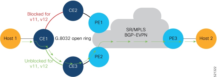
Figure 1. How EVPN E-LAN single flow-active mode works

The process involves these stages:

  1. Traffic flow initiation:

    • Host 1 sends traffic to CE1.

    • CE1 sends traffic to PE2 through CE3, as the CE1-CE3 link is in the forwarding state.

  2. MAC address learning:

    • PE2 learns Host 1's MAC address and advertises it to PE1.

    • PE2, acting as the active PE, sets the BGP local preference value to 100.

  3. Traffic routing:

    • PE1, acting as the stand-by PE, sets its BGP local preference to 80.

    • PE1 sends traffic to PE3, which forwards it to Host 2.

  4. Failure scenario:

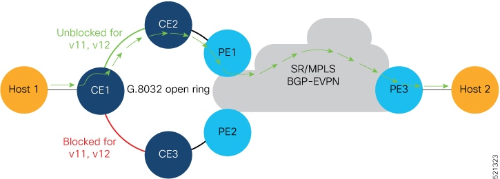
    • If the CE1-CE3 or CE3-PE2 link fails, traffic reroutes through PE1.

    • CE1-CE2 link changes to the forwarding state.

    • PE1 learns Host 1’s MAC address directly, sets its BGP local preference to 100, and routes traffic to Host 2 through PE3.

    Figure 2. Failure Scenario

Result

The EVPN E-LAN single flow-active mode ensures fast convergence by dynamically adjusting local preferences and multihoming configurations, allowing efficient traffic management and minimizing network disruption during link failures.

Configure EVPN E-LAN single-flow-active multihoming

Set up EVPN E-LAN with single-flow-active multihoming across PE1 and PE2 routers.

This task involves configuring EVPN instances on both routers to enable single-flow-active mode for enhanced load balancing and redundancy.

Procedure


Step 1

Configure advertisement of MAC routes.

Example:

Router# configure
Router(config)# evpn
Router(config-evpn)# evi 100
Router(config-evpn-instance)# advertise-mac
Router(config-evpn-instance-mac)# commit

Configure both PE1 and PE2 with the same EVI of 100.

Step 2

Configure single-flow-active load-balancing mode.

Example:

Router(config)# evpn        
Router(config-evpn)# interface bundle-ether 1
Router(config-evpn-ac)# ethernet-segment
Router(config-evpn-ac-es)# identifier type 0 36.37.00.00.00.00.00.11.01
Router(config-evpn-ac-es)# load-balancing-mode single-flow-active
Router(config-evpn-ac-es)# commit

Configure both PE1 and PE2 with the same ESI 0 36.37.00.00.00.00.00.11.01.

Step 3

Configure bridge domain and associate the evi to the bridge domain.

Example:

Router(config)# l2vpn
Router(config-l2vpn)# bridge group 100
Router(config-l2vpn-bg)# bridge-domain 100
Router(config-l2vpn-bg-bd)# interface Bundle-Ether1.2
Router(config-l2vpn-bg-bd-ac)#exit
Router(config-l2vpn-bg-bd)# evi 100
Router(config-l2vpn-bg-bd-evi)# root
Router(config)# interface Bundle-Ether1.2 l2transport
Router(config-l2vpn-subif)#encapsulation dot1q 2
Router(config-l2vpn-subif)#commit

Step 4

Running configuration of EVPN E-LAN single-flow-active multihoming.

Example:


evpn      
 evi 100  
  advertise-mac
  !       
 !        
 interface Bundle-Ether1
  ethernet-segment
   identifier type 0 36.37.00.00.00.00.00.11.01
   load-balancing-mode single-flow-active
  convergence 
      mac-mobility
   !
  !       
 !        
!         
l2vpn     
  bridge group 100
   bridge-domain 100
    interface Bundle-Ether1
   !      
   evi 100
   !      
  !       
 !
 interface Bundle-Ether1.2 l2transport
  encapsulation dot1q 2
!        
!                

Step 5

Use the show evpn ethernet-segment interface be 1 detail to verify that EVPN E-LAN single-flow-active multihoming mode is configured.

Example:

Router#show  evpn  ethernet-segment  interface  be 1 detail
Legend:
B   - No Forwarders EVPN-enabled,
C   - MAC missing (Backbone S-MAC PBB-EVPN / Grouping ES-MAC vES),
RT  - ES-Import Route Target missing,
E   - ESI missing,
H   - Interface handle missing,
I   - Name (Interface or Virtual Access) missing,
M   - Interface in Down state,
O   - BGP End of Download missing,
P   - Interface already Access Protected,
Pf  - Interface forced single-homed,
R   - BGP RID not received,
S   - Interface in redundancy standby state,
X   - ESI-extracted MAC Conflict
SHG - No local split-horizon-group label allocated
Hp  - Interface blocked on peering complete during HA event
Rc  - Recovery timer running during peering sequence

Ethernet Segment Id            Interface                          Nexthops
0 36.37.00.00.00.00.00.11.01  BE1                                 172.16.0.4
                                                                  172.16.0.5
ES to BGP Gates   : Ready
ES to L2FIB Gates : P
Main port         :
Interface name    : Bundle-Ether1
Interface MAC     : b0a6.51e5.00dd
IfHandle          : 0x2000802c
State             : Up
Redundancy        : Not Defined
ESI type          : 0
Value             : 07.0807.0807.0807.0800
ES Import RT      : 0708.0708.0708 (from ESI)
Source MAC        : 0000.0000.0000 (N/A)
Topology          :
Operational    : MH, Single-flow-active
Configured     : Single-flow-active
Service Carving   : Auto-selection
Multicast         : Disabled
Convergence       : MAC-Mobility
Mobility-Flush    : Debounce 1 sec, Count 0, Skip 0
                  : Last n/a
Peering Details   : 2 Nexthops
172.16.0.4 [MOD:P:00:T]
172.16.0.5 [MOD:P:00:T]
Service Carving Synchronization:
Mode              : NONE
Peer Updates      :
172.16.0.4 [SCT: N/A]
172.16.0.5 [SCT: N/A]
Service Carving Results:
Forwarders    : 1
Elected          : 0
Not Elected   : 0
EVPN-VPWS Service Carving Results:
Primary          : 0
Backup           : 0
Non-DF           : 0
MAC Flushing mode: STP-TCN
Peering timer    : 3 sec [not running]
Recovery timer   : 30 sec [not running]
Carving timer    : 0 sec [not running]
HRW Reset timer  : 5 sec [not running]
Local SHG label  : 24007
Remote SHG labels: 1
24010            : nexthop 172.16.0.5
Access signal mode: Bundle OOS (Default)

EVPN E-Line single-active multihoming mode

EVPN E-Line single-active multihoming mode is a network redundancy model that

  • enables PE nodes locally connected to an Ethernet segment to load balance traffic to and from the segment based on an EVI

  • ensures that within an EVI, only one PE forwards traffic to and from the Ethernet segment, and

  • supports efficient use of network resources by managing active forwarding paths.

The EVPN E-Line single-active multihoming mode uses the same conceptual framework as the EVPN E-LAN single-active multihoming mode. For more details, refer to the EVPN E-LAN single-active multihoming mode section.

Table 6. Feature History Table

Feature Name

Release Information

Feature Description

EVPN E-Line single-active multihoming mode

Release 25.2.1

Introduced in this release on: Centralized Systems (8400 [ASIC: K100]) (select variants only*)

*This feature is now supported on the Cisco 8404-SYS-D routers.

EVPN E-Line single-active multihoming mode

Release 24.4.1

Introduced in this release on: Fixed Systems (8200, 8700); Centralized Systems (8600); Modular Systems (8800 [LC ASIC: Q200]) (select variants only*)

* The EVPN E-Line single-active multi-homing mode is now extended to:

  • 8712-MOD-M

  • 8201-32FH

  • 8201-24H8FH

  • 8202-32FH-M

  • 8608

  • 88-LC0-34H14FH

  • 88-LC0-36FH

  • 88-LC0-36FH-M

EVPN E-Line single-active multihoming mode

Release 24.3.1

Introduced in this release on: Fixed Systems (8200 [ASIC: P100], 8700 [ASIC: P100])(select variants only*); Modular Systems (8800 [LC ASIC: P100])(select variants only*)

* The EVPN E-Line single-active multi-homing mode is now extended to:

  • 8212-48FH-M

  • 8711-32FH-M

  • 88-LC1-52Y8H-EM

  • 88-LC1-12TH24FH-E

EVPN E-Line single-active multihoming mode

Release 24.2.11

Introduced in this release on: Modular Systems (8800 [LC ASIC: P100]) (select variants only*)

The single-active multi-homing mode offers redundant connectivity on a single link at a time with failover to the second link in case the active link fails. In this mode, only a single PE among a group of PEs attached to an Ethernet segment forwards traffic to and from that Ethernet Segment.

* This feature is supported only on routers with the 88-LC1-36EH line cards.

Configure EVPN E-Line single-active multihoming mode

Configure an EVPN E-Line service in single-active multihoming mode to provide redundancy while allowing only one active link per Ethernet segment.

In single-active multihoming mode, only one PE device in a redundant pair actively forwards traffic for a given Ethernet segment, ensuring loop-free forwarding and simplified failover. This configuration is typically used in point-to-point (p2p) services where load sharing is not required.

Procedure


Step 1

Create a cross-connect group on all the PE devices.

Example:


Router# configure 
Router(config)# l2vpn 
Router(config-l2vpn)# xconnect group xg1

Step 2

Configure point-to-point (p2p) cross-connect and assign an interface to the cross-connect on all the PE devices.

  1. Point-to-point (p2p) cross-connect and assign an interface to the cross-connect on PE1.

    Example:

    
    Router(config-l2vpn-xc)# p2p e1_5-6
    Router(config-l2vpn-xc-p2p)# interface Bundle-Ether10.2
    
  2. Point-to-point (p2p) cross-connect and assign an interface to the cross-connect on PE2.

    Example:

    
    Router(config-l2vpn-xc)# p2p e1_5-6
    Router(config-l2vpn-xc-p2p)# interface Bundle-Ether10.2
    
  3. Point-to-point (p2p) cross-connect and assign an interface to the cross-connect on PE3.

    Example:

    
    Router(config-l2vpn-xc)# p2p e1_5-6
    Router(config-l2vpn-xc-p2p)# interface Bundle-Ether20.1
    
  4. Point-to-point (p2p) cross-connect and assign an interface to the cross-connect on PE4.

    Example:

    
    Router(config-l2vpn-xc)# p2p e1_5-6
    Router(config-l2vpn-xc-p2p)# interface Bundle-Ether20.1
    

Step 3

Enable EVPN E-Line endpoint on the p2p cross-connect and configure the ESI on all PE devices.

  1. Enable EVPN E-Line endpoint on the p2p cross-connect and configure the ESI on PE1.

    Example:

    Router(config-l2vpn-xc-p2p)# neighbor evpn evi 1 target 5 source 6
    Router(config-l2vpn-xc-p2p)#  root
    Router(config)# evpn
    Router(config-evpn)# interface Bundle-Ether10
    Router(config-evpn-ac)#  ethernet-segment
    Router(config-evpn-ac-es)# identifier type 0 00.01.00.ac.ce.55.00.0a.00 
    
  2. Enable EVPN E-Line endpoint on the p2p cross-connect and configure the ESI on PE2.

    Example:

    Router(config-l2vpn-xc-p2p)# neighbor evpn evi 1 target 5 source 6
    Router(config-l2vpn-xc-p2p)#  root
    Router(config)# evpn
    Router(config-evpn)# interface Bundle-Ether10
    Router(config-evpn-ac)#  ethernet-segment
    Router(config-evpn-ac-es)# identifier type 0 00.01.00.ac.ce.55.00.0a.00 
    
  3. Enable EVPN E-Line endpoint on the p2p cross-connect and configure the ESI on PE3.

    Example:

    Router(config-l2vpn-xc-p2p)# neighbor evpn evi 1 target 6 source 5
    Router(config-l2vpn-xc-p2p)#  root
    Router(config)# evpn
    Router(config-evpn)# interface Bundle-Ether20
    Router(config-evpn-ac)# ethernet-segment
    Router(config-evpn-ac-es)# identifier type 0 00.01.00.ac.ce.55.00.14.00 
    
  4. Enable EVPN E-Line endpoint on the p2p cross-connect and configure the ESI on PE4.

    Example:

    Router(config-l2vpn-xc-p2p)# neighbor evpn evi 1 target 6 source 5
    Router(config-l2vpn-xc-p2p)#  root
    Router(config)# evpn
    Router(config-evpn)# interface Bundle-Ether20
    Router(config-evpn-ac)# ethernet-segment
    Router(config-evpn-ac-es)# identifier type 0 00.01.00.ac.ce.55.00.14.00 
    

Step 4

Enable single-active load balancing mode on all the PE devices.

Example:

Router(config-evpn-ac-es)# load-balancing-mode single-active
Router(config-evpn-ac-es)# commit 

Step 5

Running configuration of EVPN E-Line single-active multihoming mode.

Example:

/* On PE1 */
!
l2vpn xconnect group xg1
 p2p e1_5-6
  interface Bundle-Ether10.2
  neighbor evpn evi 1 target 5 source 6
!
evpn
interface Bundle-Ether10
  ethernet-segment
   identifier type 0 00.01.00.ac.ce.55.00.0a.00
   load-balancing-mode single-active
!


/* On PE2 */
!
l2vpn xconnect group xg1
 p2p e1_5-6
  interface Bundle-Ether10.2
  neighbor evpn evi 1 target 5 source 6
!
evpn
interface Bundle-Ether10
  ethernet-segment
   identifier type 0 00.01.00.ac.ce.55.00.0a.00
   load-balancing-mode single-active
!

/* On PE3 */
!
l2vpn xconnect group xg1
 p2p e1_5-6
  interface Bundle-Ether20.1
  neighbor evpn evi 1 target 6 source 5
!
evpn
interface Bundle-Ether20
  ethernet-segment
   identifier type 0 00.01.00.ac.ce.55.00.14.00
   load-balancing-mode single-active
!

/* On PE4 */
!
l2vpn xconnect group xg1
 p2p e1_5-6
  interface Bundle-Ether20.1
  neighbor evpn evi 1 target 6 source 5
!
evpn
interface Bundle-Ether20
  ethernet-segment
   identifier type 0 00.01.00.ac.ce.55.00.14.00
   load-balancing-mode single-active
!

EVPN E-Line all-active multihoming mode

An EVPN E-Line all-active multihoming mode is a networking model that

  • enables multiple simultaneous active connections from an EVPN to a single Ethernet LAN

  • allows all PE routers attached to a particular Ethernet segment to forward traffic to and from that Ethernet segment, and

  • provides redundancy and load balancing by allowing traffic distribution across all available links, enhancing network reliability and efficiency by utilizing all potential paths without requiring a failover mechanism.

The EVPN E-Line all-active multihoming mode uses the same conceptual framework as the EVPN E-Line all-active multihoming mode. For more details, refer to the EVPN E-LAN all-active multihoming mode section.

Table 7. Feature History Table

Feature Name

Release Information

Feature Description

E-Line all-active multihoming mode

Release 25.2.1

Introduced in this release on: Centralized Systems (8400 [ASIC: K100]) (select variants only*)

*This feature is now supported on the Cisco 8404-SYS-D routers.

E-Line all-active multihoming mode

Release 24.4.1

Introduced in this release on: Fixed Systems (8200, 8700) ; Centralized Systems (8600); Modular Systems (8800 [LC ASIC: Q200])(select variants only*)

*The EVPN E-line all-active multi-homing mode is now extended to:

  • 8712-MOD-M

  • 8201-32FH

  • 8201-24H8FH

  • 8202-32FH-M

  • 8608

  • 88-LC0-34H14FH

  • 88-LC0-36FH

  • 88-LC0-36FH-M

E-Line all-active multihoming mode

Release 24.3.1

Introduced in this release on: Fixed Systems (8200, 8700); Modular Systems (8800 [LC ASIC: P100]) (select variants only*)

*The E-Line all-active multi-homing mode is now extended to:

  • 8212-48FH-M

  • 8711-32FH-M

  • 88-LC1-52Y8H-EM

  • 88-LC1-12TH24FH-E

E-Line all-active multihoming mode

Release 24.2.11

Introduced in this release on: Modular Systems (8800 [LC ASIC: P100]) (select variants only*)

In all-active multihoming mode, multiple PE devices connected to the same CE are simultaneously active. Traffic is distributed across all active links, optimizing bandwidth usage and ensuring high availability.

* This feature is supported only on routers with the 88-LC1-36EH line cards.

Configure EVPN E-Line all-active multihoming mode

Configure an EVPN E-Line service in all-active multihoming mode to enable load balancing and redundancy across multiple links.

In all-active multihoming mode, all PE devices in a redundant set actively forward traffic for the same Ethernet segment. This allows efficient bandwidth utilization and rapid failover while maintaining loop-free connectivity.

Procedure


Step 1

Create a cross-connect group on all the PE devices.

Example:


Router# configure 
Router(config)# l2vpn 
Router(config-l2vpn)# xconnect group xg1

Step 2

Configure point-to-point (p2p) cross-connect and assign an interface to the cross-connect on all the PE devices.

  1. Point-to-point (p2p) cross-connect and assign an interface to the cross-connect on PE1.

    Example:

    
    Router(config-l2vpn-xc)# p2p e1_5-6
    Router(config-l2vpn-xc-p2p)# interface Bundle-Ether10.2
    
  2. Point-to-point (p2p) cross-connect and assign an interface to the cross-connect on PE2.

    Example:

    
    Router(config-l2vpn-xc)# p2p e1_5-6
    Router(config-l2vpn-xc-p2p)# interface Bundle-Ether10.2
    
  3. Point-to-point (p2p) cross-connect and assign an interface to the cross-connect on PE3.

    Example:

    
    Router(config-l2vpn-xc)# p2p e1_5-6
    Router(config-l2vpn-xc-p2p)# interface Bundle-Ether20.1
    
  4. Point-to-point (p2p) cross-connect and assign an interface to the cross-connect on PE4.

    Example:

    
    Router(config-l2vpn-xc)# p2p e1_5-6
    Router(config-l2vpn-xc-p2p)# interface Bundle-Ether20.1
    

Step 3

Enable EVPN E-Line endpoint on all PE devices.

  1. Enable EVPN E-Line endpoint on the p2p cross-connect for PE1.

    Example:

    Router(config-l2vpn-xc-p2p)# neighbor evpn evi 1 target 5 source 6
    
  2. Enable EVPN E-Line endpoint on the p2p cross-connect for PE2.

    Example:

    Router(config-l2vpn-xc-p2p)# neighbor evpn evi 1 target 5 source 6 
    
  3. Enable EVPN E-Line endpoint on the p2p cross-connect for PE3.

    Example:

    Router(config-l2vpn-xc-p2p)# neighbor evpn evi 1 target 6 source 5 
    
  4. Enable EVPN E-Line endpoint on the p2p cross-connect for PE4.

    Example:

    Router(config-l2vpn-xc-p2p)# neighbor evpn evi 1 target 6 source 5 
    

Step 4

Configure the ESI on all PE devices.

  1. Configure the ESI on PE1.

    Example:

    Router(config)# evpn
    Router(config-evpn)# interface Bundle-Ether10
    Router(config-evpn-ac)# ethernet-segment
    Router(config-evpn-ac-es)# identifier type 0 00.01.00.ac.ce.55.00.0a.00 
    
  2. Configure the ESI on PE2.

    Example:

    Router(config)# evpn
    Router(config-evpn)# interface Bundle-Ether10
    Router(config-evpn-ac)# ethernet-segment
    Router(config-evpn-ac-es)# identifier type 0 00.01.00.ac.ce.55.00.0a.00 
    
  3. Configure the ESI on PE3.

    Example:

    Router(config)# evpn
    Router(config-evpn)# interface Bundle-Ether20
    Router(config-evpn-ac)# ethernet-segment
    Router(config-evpn-ac-es)# identifier type 0 00.01.00.ac.ce.55.00.14.00 
    
  4. Configure the ESI on PE4.

    Example:

    Router(config)# evpn
    Router(config-evpn)# interface Bundle-Ether20
    Router(config-evpn-ac)# ethernet-segment
    Router(config-evpn-ac-es)# identifier type 0 00.01.00.ac.ce.55.00.14.00 
    

Step 5

Running configuration of EVPN E-Line all-active multihoming mode.

Example:

/* On PE1 */
!
configure
l2vpn xconnect group xg1
 p2p e1_5-6
  interface Bundle-Ether10.2
  neighbor evpn evi 1 target 5 source 6
!
evpn
interface Bundle-Ether10
  ethernet-segment
   identifier type 0 00.01.00.ac.ce.55.00.0a.00

!


/* On PE2 */
!
configure
l2vpn xconnect group xg1
 p2p e1_5-6
  interface Bundle-Ether10.2
  neighbor evpn evi 1 target 5 source 6
!
evpn
interface Bundle-Ether10
  ethernet-segment
   identifier type 0 00.01.00.ac.ce.55.00.0a.00

!

/* On PE3 */
!
configure
l2vpn xconnect group xg1
 p2p e1_5-6
  interface Bundle-Ether20.1
  neighbor evpn evi 1 target 6 source 5
!
evpn
interface Bundle-Ether20
  ethernet-segment
      identifier type 0 00.01.00.ac.ce.55.00.14.00

!

/* On PE4 */
!
configure
l2vpn xconnect group xg1
 p2p e1_5-6
  interface Bundle-Ether20.1
  neighbor evpn evi 1 target 6 source 5
!
evpn
interface Bundle-Ether20
  ethernet-segment
      identifier type 0 00.01.00.ac.ce.55.00.14.00

!

EVPN E-Line port-active multihoming mode

An EVPN E-Line port-active multihoming is a network model that

  • supports single-active redundancy load balancing at the port-level or interface-level

  • provides faster convergence during a link failure, and

  • enables protocol simplification by having only one physical port active at a given time.

The EVPN E-Line port-active multihoming mode uses the same conceptual framework as the EVPN E-LAN port-active multihoming mode. For more details, refer to the EVPN E-LAN port-active multihoming mode section.

Table 8. Feature History Table

Feature Name

Release Information

Feature Description

EVPN E-Line port-active multihoming mode

Release 25.2.1

Introduced in this release on: Centralized Systems (8400 [ASIC: K100]) (select variants only*)

*This feature is now supported on the Cisco 8404-SYS-D routers.

EVPN E-Line port-active multihoming mode

Release 24.4.1

Introduced in this release on: Fixed Systems (8200 [ASIC: P100], 8700 [ASIC: P100])(select variants only*); Modular Systems (8800 [LC ASIC: P100])(select variants only*)

*The EVPN E-Line port-active multi-homing mode is now extended to:

  • 8712-MOD-M

  • 8201-32FH

  • 8201-24H8FH

  • 8202-32FH-M

  • 8608

  • 88-LC0-34H14FH

  • 88-LC0-36FH

  • 88-LC0-36FH-M

EVPN E-Line port-active multihoming mode

Release 24.3.1

Introduced in this release on: Fixed Systems (8200, 8700); Modular Systems (8800 [LC ASIC: P100]) (select variants only*)

*The EVPN E-Line port-active multi-homing mode is now extended to:

  • 8212-48FH-M

  • 8711-32FH-M

  • 88-LC1-52Y8H-EM

  • 88-LC1-12TH24FH-E

EVPN E-Line port-active multihoming mode

Release 24.2.11

Introduced in this release on: Modular Systems (8800 [LC ASIC: P100]) (select variants only*)

The port-active multi-homing mode enables single-active redundancy load balancing at the port-level or the interface-level. In this mode, one of the PEs remains active at the port-level. This feature enables protocol simplification as only one of the physical ports is active at a given time.

* This feature is supported only on routers with the 88-LC1-36EH line cards.

Configure EVPN E-Line port-active multihoming mode

Configure an EVPN E-Line service in port-active multihoming mode to provide redundancy while ensuring only one active link per port for a given Ethernet segment.

In port-active multihoming mode, only one port in an Ethernet segment actively forwards traffic, while others remain in standby mode. This mode is typically used in access networks where per-port active-standby control is required for operational or design reasons.

Procedure


Step 1

Create a cross-connect group on all the PE devices.

Example:


Router# configure 
Router(config)# l2vpn 
Router(config-l2vpn)# xconnect group xg1

Step 2

Configure point-to-point (p2p) cross-connect and assign an interface to the cross-connect on all the PE devices.

  1. Point-to-point (p2p) cross-connect and assign an interface to the cross-connect on PE1.

    Example:

    
    Router(config-l2vpn-xc)# p2p e1_5-6
    Router(config-l2vpn-xc-p2p)# interface Bundle-Ether10.2
    
  2. Point-to-point (p2p) cross-connect and assign an interface to the cross-connect on PE2.

    Example:

    
    Router(config-l2vpn-xc)# p2p e1_5-6
    Router(config-l2vpn-xc-p2p)# interface Bundle-Ether10.2
    
  3. Point-to-point (p2p) cross-connect and assign an interface to the cross-connect on PE3.

    Example:

    
    Router(config-l2vpn-xc)# p2p e1_5-6
    Router(config-l2vpn-xc-p2p)# interface Bundle-Ether20.1
    
  4. Point-to-point (p2p) cross-connect and assign an interface to the cross-connect on PE4.

    Example:

    
    Router(config-l2vpn-xc)# p2p e1_5-6
    Router(config-l2vpn-xc-p2p)# interface Bundle-Ether20.1
    

Step 3

Enable EVPN E-Line endpoint on the p2p cross-connect and configure the ESI on all PE devices.

  1. Enable EVPN E-Line endpoint on the p2p cross-connect and configure the ESI on PE1.

    Example:

    Router(config-l2vpn-xc-p2p)# neighbor evpn evi 1 target 5 source 6
    Router(config-l2vpn-xc-p2p)#  root
    Router(config)# evpn
    Router(config-evpn)# interface Bundle-Ether10
    Router(config-evpn-ac)#  ethernet-segment
    Router(config-evpn-ac-es)# identifier type 0 00.01.00.ac.ce.55.00.0a.00 
    
  2. Enable EVPN E-Line endpoint on the p2p cross-connect and configure the ESI on PE2.

    Example:

    Router(config-l2vpn-xc-p2p)# neighbor evpn evi 1 target 5 source 6
    Router(config-l2vpn-xc-p2p)#  root
    Router(config)# evpn
    Router(config-evpn)# interface Bundle-Ether10
    Router(config-evpn-ac)#  ethernet-segment
    Router(config-evpn-ac-es)# identifier type 0 00.01.00.ac.ce.55.00.0a.00 
    
  3. Enable EVPN E-Line endpoint on the p2p cross-connect and configure the ESI on PE3.

    Example:

    Router(config-l2vpn-xc-p2p)# neighbor evpn evi 1 target 6 source 5
    Router(config-l2vpn-xc-p2p)#  root
    Router(config)# evpn
    Router(config-evpn)# interface Bundle-Ether20
    Router(config-evpn-ac)# ethernet-segment
    Router(config-evpn-ac-es)# identifier type 0 00.01.00.ac.ce.55.00.14.00 
    
  4. Enable EVPN E-Line endpoint on the p2p cross-connect and configure the ESI on PE4.

    Example:

    Router(config-l2vpn-xc-p2p)# neighbor evpn evi 1 target 6 source 5
    Router(config-l2vpn-xc-p2p)#  root
    Router(config)# evpn
    Router(config-evpn)# interface Bundle-Ether20
    Router(config-evpn-ac)# ethernet-segment
    Router(config-evpn-ac-es)# identifier type 0 00.01.00.ac.ce.55.00.14.00 
    

Step 4

Enable port-active load balancing mode on all the PE devices.

Example:

Router(config-evpn-ac-es)# load-balancing-mode port-active
Router(config-evpn-ac-es)# commit 

Step 5

Running configuration of EVPN E-Line port-active multihoming mode.

Example:

/* On PE1 */
!
l2vpn xconnect group xg1
 p2p e1_5-6
  interface Bundle-Ether10.2
  neighbor evpn evi 1 target 5 source 6
!
evpn
interface Bundle-Ether10
  ethernet-segment
   identifier type 0 00.01.00.ac.ce.55.00.0a.00
   load-balancing-mode port-active
!


/* On PE2 */
!
l2vpn xconnect group xg1
 p2p e1_5-6
  interface Bundle-Ether10.2
  neighbor evpn evi 1 target 5 source 6
!
evpn
interface Bundle-Ether10
  ethernet-segment
   identifier type 0 00.01.00.ac.ce.55.00.0a.00
   load-balancing-mode port-active
!

/* On PE3 */
!
l2vpn xconnect group xg1
 p2p e1_5-6
  interface Bundle-Ether20.1
  neighbor evpn evi 1 target 6 source 5
!
evpn
interface Bundle-Ether20
  ethernet-segment
   identifier type 0 00.01.00.ac.ce.55.00.14.00
   load-balancing-mode port-active
!

/* On PE4 */
!
l2vpn xconnect group xg1
 p2p e1_5-6
  interface Bundle-Ether20.1
  neighbor evpn evi 1 target 6 source 5
!
evpn
interface Bundle-Ether20
  ethernet-segment
   identifier type 0 00.01.00.ac.ce.55.00.14.00
   load-balancing-mode port-active
!