Fundamentals and Core Features of EVPN

This chapter summarizes essential EVPN E-LAN features, including BUM ingress replication, split-horizon groups, core isolation, and cost-out. Users can learn how to efficiently manage BUM traffic, prevent loops, ensure core stability, and perform seamless maintenance in EVPN networks.

BUM ingress replication for EVPN E-LAN

EVPN BUM ingress replication is a network process that

  • replicates broadcast, unknown unicast, and multicast (BUM) traffic at the ingress provider edge (PE) device

  • uses ingress replication to deliver BUM traffic to all remote PE devices within the EVPN E-LAN instance, and

  • eliminates the need for multicast routing protocols or multicast trees in the provider network.

Table 1. Feature History Table

Feature Name

Release Information

Feature Description

BUM ingress replication for EVPN E-LAN

Release 25.3.1

Introduced in this release on: Centralized Systems (8400 [ASIC: K100]) (select variants only*)

*This feature is now supported on the Cisco 8404-SYS-D routers.

BUM ingress replication for EVPN E-LAN

Release 24.4.1

Introduced in this release on: Fixed Systems (8700) (select variants only*)

* The BUM ingress replication functionality is now extended to the Cisco 8712-MOD-M routers.

BUM ingress replication for EVPN E-LAN

Release 24.3.1

Introduced in this release on: Fixed Systems (8200 [ASIC: Q200, P100], 8700 [ASIC: P100])(select variants only*); Modular Systems (8800 [LC ASIC: Q100, Q200, P100])(select variants only*

* The BUM ingress replication functionality is now extended to:

  • 8212-48FH-M

  • 8711-32FH-M

  • 88-LC1-52Y8H-EM

  • 88-LC1-12TH24FH-E

BUM ingress replication for EVPN E-LAN

Release 24.2.11

Introduced in this release on: Modular Systems (8800 [LC ASIC: P100]) (select variants only*)

* The BUM ingress replication functionality is now extended to routers with the 88-LC1-36EH line cards.

BUM ingress replication for EVPN E-LAN

Release 7.11.1

You can optimize Broadcast, Unknown Unicast, and Multicast (BUM) traffic by ensuring that traffic that a device receives is replicated and forwarded to only those CE devices in an EVPN network, if and when they require it. This reduction in the unnecessary forwarding of BUM traffic prevents the flooding of BUM traffic to all devices on the EVPN network.

This feature is supported only on Q200-based line cards.

This feature is enabled by default.

Feature highlights of BUM ingress replication for EVPN E-LAN

EVPN BUM ingress replication enhances network efficiency and security by:

  • optimizing resource allocation through forwarding BUM traffic only to necessary EVPN instances or VRFs, thereby minimizing traffic flooding,

  • reducing congestion and preserving bandwidth within the broadcast domain,

  • lowering overhead and mitigating potential performance issues,

  • ensuring effective BUM traffic management to support network scalability without overwhelming broadcast or multicast traffic,

  • improving network security by selectively duplicating BUM traffic to designated recipients, limiting exposure to unintended devices and reducing unauthorized access risks, and

  • preventing broadcast storms and network disruptions by restricting traffic forwarding to intended devices only.

How BUM ingress replication works

Summary

The key components involved in the EVPN BUM traffic process are:

  • Ingress router: learns MAC addresses related to BUM traffic and collects multicast group membership information.

  • BGP: signals and distributes MAC and multicast information to other routers within the EVPN network.

Workflow

These stages describe how BUM ingress replication works.

  1. The ingress router learns MAC addresses associated with BUM traffic and gathers multicast group membership details.
  2. Instead of flooding BUM traffic to all ports in the EVPN, the ingress router replicates the traffic only to the specific EVPN instances or VRFs where it is required.
  3. BGP distributes the MAC and multicast information to other routers in the EVPN network.
  4. The ingress router replicates and forwards the BUM traffic to the designated EVPN instances or VRFs, ensuring traffic reaches only the appropriate destinations.

Result

This process optimizes network efficiency by limiting BUM traffic replication to necessary locations, reducing unnecessary flooding and improving overall EVPN traffic management.
Split-horizon groups for EVPN E-LAN

A split-horizon group is a network loop prevention method that

  • places forwarding or flooding restrictions between bridge ports based on group membership

  • aggregates attachment circuits (ACs) and pseudowires (PWs) into one of three groups called split-horizon groups, and

  • influences the flooding and forwarding behavior within bridge domains between members of a split-horizon group.

Table 2. Feature History Table

Feature Name

Release Information

Feature Description

Split-horizon groups for EVPN E-LAN

Release 25.3.1

Introduced in this release on: Centralized Systems (8400 [ASIC: K100]) (select variants only*)

*This feature is now supported on the Cisco 8404-SYS-D routers.

Split-horizon groups for EVPN E-LAN

Release 24.4.1

Introduced in this release on: Fixed Systems (8700) (select variants only*)

* The split-horizon groups functionality is now extended to the Cisco 8712-MOD-M routers.

Split-horizon groups for EVPN E-LAN

Release 24.3.1

Introduced in this release on: Modular Systems (8800 [LC ASIC: P100]) (select variants only*)

* The split-horizon groups functionality is now extended to:

  • 8212-48FH-M

  • 8711-32FH-M

  • 88-LC1-52Y8H-EM

  • 88-LC1-12TH24FH-E

Split-horizon groups for EVPN E-LAN

Release 24.2.11

Introduced in this release on: Modular Systems (8800 [LC ASIC: P100]) (select variants only*)

* The split-horizon groups functionality is now extended to routers with the 88-LC1-36EH line cards.

Split-horizon groups for EVPN E-LAN

Release 7.11.1

You can prevent unnecessary BUM traffic flooding and conserve bandwidth for single-homed EVPN scenarios by ensuring that the traffic isn’t sent back to the CE device from which it originated. Depending on the type of traffic you need to be forwarded or distributed, you can configure split-horizon group 0 (SG 0), SG 1, or SG 2.

This feature is supported only on Q200-based line cards.

The feature introduces the split-horizon group command.

Split-horizon behavior in bridge domains

When applying the split-horizon method to bridge domains, these behaviors define traffic handling:

  • Traffic between members of a split-horizon group is forwarded as either unicast or flooded.

  • Forwarding restrictions are applied to prevent loops within the network.

  • Group membership controls how traffic flows between members.

Split-horizon group forwarding and flooding behaviors

Traffic flooding occurs for broadcast, multicast, and unknown unicast destination addresses. Unicast traffic refers to frames sent to bridge ports where the destination MAC address is known.

Flooding traffic includes:

  • Frames with unknown unicast destination MAC addresses.

  • Frames sent to Ethernet multicast addresses, such as Spanning Tree Bridge Protocol Data Units (BPDUs).

  • Ethernet broadcast frames with the MAC address FF-FF-FF-FF-FF-FF.

Within the network, members are organized into groups that control traffic flow:

  • Members within the same group are prohibited from sending traffic to each other.

  • Members in different groups can send traffic to each other without restrictions.

This grouping segments the network into unique routes, which improves traffic control and reduces packet congestion, thereby enhancing network performance and reliability.

The table summarizes the behavior of frames received on one member of a split-horizon group, including whether traffic is forwarded to other members of the same group, and the assignment of Bridge Ports (BPs) to groups

Split-horizon group

Behavior

0

Default AC group with no forwarding or flooding restrictions. Forwards and floods traffic within the group and between all groups. All L2 ACs are added to this group by default and cannot be manually assigned via CLI.

1

Default VFI (core) PW group. Forwarding or flooding of traffic is restricted between bridge ports in this group but allowed to all other groups. All EVPN EVI virtual ports and VFI PWs are added to this group and cannot be manually assigned via CLI.

2

Optional AC group. Forwarding or flooding of traffic is restricted between bridge ports in this group but allowed to all other groups. ACs can be manually added to this group via CLI, but not VFI PWs.

Configure the split-horizon groups for EVPN E-LAN

Configure split-horizon groups to control traffic forwarding and prevent loops within L2VPN bridge domains.

Use this task when setting up L2VPN bridge domains that require split-horizon group configuration to isolate traffic between interfaces and pseudowires.

Procedure


Step 1

Create a bridge group and enter a bridge domain within the bridge group.

Example:

Router# configure
Router(config)# l2vpn
Router(config-l2vpn)# bridge group bg
Router(config-l2vpn-bg)# bridge-domain bd

Step 2

Configure interfaces and assign them to the bridge domain.

  1. Assign interface HundredGigE 0/0/0/24 to the default split-horizon group 0.

    Example:

    Router(config-l2vpn-bg-bd-ac)# interface HundredGigE 0/0/0/24<- (split-horizon group 0, default)
  2. Assign interface HundredGigE 0/0/0/24.1 without specifying a split-horizon group (inherits default).

    Example:

    Router(config-l2vpn-bg-bd-ac)# interface HundredGigE 0/0/0/24.1

Step 3

Configure an Ethernet Virtual Instance (EVI) and assign a split-horizon group.

Example:

Router(config-l2vpn-bg-bd)# evi 200
Router(config-l2vpn-bg-bd-evi)# split-horizon group<- (split-horizon group 2)

Step 4

Configure a pseudowire (PW) and assign it to a split-horizon group.

Example:

Router(config-l2vpn-bg-bd-evi)# neighbor 10.0.0.1 pw-id 1
Router(config-l2vpn-bg-bd-pw)# split-horizon group <- (split-horizon group 2)

Step 5

Configure a neighbor for the VFI with the default split-horizon group 1.

Example:

Router(config-l2vpn-bg-bd-pw)# vfi vf
Router(config-l2vpn-bg-bd-vfi)# neighbor 172.16.0.1 pw-id 10001 <- (split-horizon group 1, default)
Router(config-l2vpn-bg-bd-vfi)# commit

Step 6

Running configuration of split-horizon groups for EVPN E-LAN.

Example:


l2vpn
  bridge group bg
   bridge-domain bd
    interface HundredGigE 0/0/0/24 <- (split-horizon group 0, default)
    interface HundredGigE 0/0/0/24.1
   !

     split-horizon group <- (split-horizon group 2)
    neighbor 10.0.0.1 pw-id 1
     split-horizon group <- (split-horizon group 2)
    vfi vf
      neighbor 172.16.0.1 pw-id 10001 <- (split-horizon group 1, default)
  !
   evi 200
!

Step 7

Use the show l2vpn bridge-domain detail command to verify the split-horizon group configuration.

Example:


Router# show l2vpn bridge-domain detail | i "AC:|Split Horizon|PW:|VFI"
MAC withdraw for Access PW: enabled
Split Horizon Group: none
P2MP PW: disabled
ACs: 2 (2 up), VFIs: 1, PWs: 2 (0 up), PBBs: 0 (0 up), VNIs: 0 (0 up)
AC: HundredGigE 0/0/0/24, state is up
Split Horizon Group: none
AC: HundredGigE 0/0/0/24.1, state is up
Split Horizon Group: enabled 
PW: neighbor 10.0.0.1, pw-id 1, state is up ( established )
Split Horizon Group: enabled
List of VFIs:
VFI vf (up)
PW: neighbor 172.16.0.1, pw-id 10001, state is up ( established )
Split Horizon Group: none
The split-horizon groups are configured for your EVPN E-LAN, isolating traffic as intended and preventing L2 forwarding loops.

Core isolation techniques in EVPN

Core isolation techniques in EVPN are network methods that

  • segregate control and data plane operations to enhance network stability

  • monitor interface states to maintain isolation in EVPN E-LAN environments, and

  • detect and isolate faulty peers through peer failure detection to prevent network disruption.

This section outlines key core isolation methods in EVPN, focusing on interface tracking for EVPN E-LAN environments and peer failure detection capabilities that enhance network resilience and stability.

Core isolation by interface tracking for EVPN E-LAN

Core isolation is a network management technique that

  • monitors the state of interfaces connecting to the core provider edge

  • isolates the core provider edge device upon interface failure, and

  • ensures the rest of the network remains operational and unaffected.

Table 3. Feature History Table

Feature Name

Release Information

Feature Description

Core isolation by interface tracking for EVPN E-LAN

Release 25.3.1

Introduced in this release on: Centralized Systems (8400 [ASIC: K100]) (select variants only*)

*This feature is now supported on the Cisco 8404-SYS-D routers.

Core isolation by interface tracking for EVPN E-LAN

Release 24.4.1

Introduced in this release on: Fixed Systems (8700) (select variants only*)

* The core isolation by interface tracking functionality is now extended to the Cisco 8712-MOD-M routers.

Core isolation by interface tracking for EVPN E-LAN

Release 24.3.1

Introduced in this release on: Fixed Systems (8200 [ASIC: P100], 8700 [ASIC: P100])(select variants only*); Modular Systems (8800 [LC ASIC: P100])(select variants only*)

* The core isolation by interface tracking functionality is now extended to:

  • 8212-48FH-M

  • 8711-32FH-M

  • 88-LC1-52Y8H-EM

  • 88-LC1-12TH24FH-E

Core isolation by interface tracking for EVPN E-LAN

Release 24.2.11

Introduced in this release on: Modular Systems (8800 [LC ASIC: P100]) (select variants only*)

* The core isolation by interface tracking functionality is now extended to routers with the 88-LC1-36EH line cards.

Core isolation by interface tracking for EVPN E-LAN

Release 7.11.1

You can now monitor the connectivity of the customer-facing interface on the PE router using object tracking (OT). If the interface fails or becomes unavailable, the router isolates the customer site from the rest of the EVPN network. Isolating the core from the network prevents the customer site from advertising its routes to other sites on the EVPN single-home network, ensuring that traffic isn't sent to the failed PE router.

Object tracking involves continuous monitoring of network interfaces, including links or ports on routers. By actively observing the status of these interfaces, administrators can dynamically adjust the network configuration based on their availability and health.

This feature is supported only on Q200-based line cards.

Use Object Tracking commands to track and monitor the connected interfaces.

Core provider edge isolation technique

The core provider edge isolationtechnique uses tracking objects assigned to the relevant interfaces. The tracking objects continuously check interface status, such as link up or link down, enabling isolation of the core provider edge device if any connected interface experiences issues or failures.

By isolating the core provider edge device in this way, network stability and continuity are maintained, preventing localized interface problems from impacting the broader network.

Supported functions of object tracking

Object tracking supports these capabilities:

  • Monitors specific network elements (such as static routes or interface statuses) as tracked objects.

  • Each tracked object is assigned a unique name using the track command in configuration mode.

  • The router monitors the state of each tracked object:

    • up—the object is functioning as expected.

    • down—the object is not functioning.

When a tracked object's state changes, the tracking process receives a notification. The tracked object can be associated with a wide variety of actions, without requiring a direct relationship between the objects themselves.

Boolean logic functions for tracking lists:

  • AND function—the tracked list is considered up only if every object in the subset is up.

  • OR function—the tracked list is considered up if at least one object in the subset is up.

Benefits of object tracking

Object tracking offers significant advantages for network management by enabling continuous oversight and responsive control of critical network elements. The key benefits include:

  • Real-time monitoring of network components, ensuring the reachability and availability of essential objects within the network.

  • Automation of network management tasks, allowing dynamic failover and load balancing actions to be executed automatically based on the state changes of tracked objects.

  • Enhanced network availability through rapid detection and response to status changes, facilitating proactive measures that reduce potential downtime.

  • Policy-driven actions that trigger specific responses when a tracked object's state changes, providing flexible and tailored network management aligned with current network conditions.

How core isolation by interface tracking works

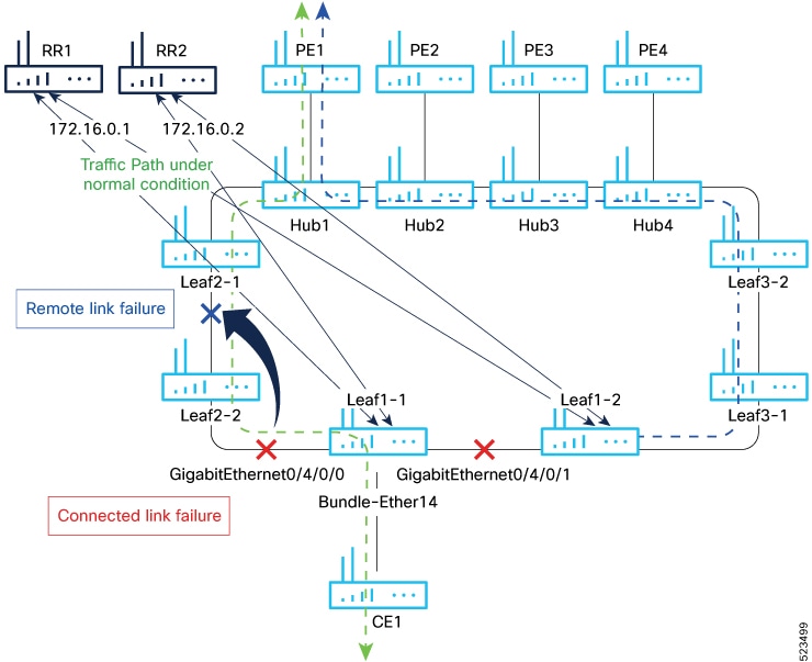
This process addresses how to detect and isolate link failures affecting traffic flow from CE1 to PE1, focusing on distinguishing between local and remote link failures.

Summary

The key components involved in the core isolation process are:

  • CE1: The customer edge device that initiates traffic from Leaf1-1.

  • Leaf1-1: The leaf switch that forwards traffic and monitors link connectivity.

  • Route reflectors (RRs): Devices maintaining BGP sessions with Leaf1-1.

  • Bundle-Ether14: The interface bundle connecting Leaf1-1 to CE1.

Workflow

Figure 1. Core isolation by interface tracking

These stages describe how core isolation by interface tracking works:

  1. CE1 sends traffic through Leaf1-1 towards PE1.
  2. Leaf1-1 monitors connectivity on both local and remote links.
  3. If Leaf1-1 loses connectivity on both local and remote links, BGP sessions to both route reflectors go down.
  4. Upon BGP session failure, Leaf1-1 disables the Bundle-Ether14 interface connected to CE1.
  5. Interface tracking is used to detect local link failures by monitoring connected interfaces.
  6. For remote link failures, interface tracking alone is insufficient; BGP session tracking is required to identify these failures.

Result

This process enables accurate detection and isolation of link failures by combining interface and BGP session tracking, ensuring appropriate interface shutdowns to maintain network stability.

Configure EVPN core isolation by interface tracking

Configure EVPN core isolation to monitor interface and BGP neighbor states and trigger actions based on their status.

Use this task to isolate the EVPN core by tracking interface line protocol states and BGP neighbor address-family states, combining these tracked objects with Boolean logic to control interface behavior.


Note


  • An object must exist before it can be added to a tracked list.

    A tracked list contains one or more objects. The Boolean expression enables tracking objects using either AND or OR operators. For example, when tracking two interfaces, using the AND operator, up means that both interfaces are up, and down means that either interface is down.

  • The NOT operator is specified for one or more objects and negates the state of the object.

  • After configuring the tracked object, you must associate the neighbor or interface whose state must be tracked.


Before you begin

In this example, Leaf1-1 brings the down the AC connected to CE1 when:

Both local interfaces GigabitEthernet0/4/0/0 and GigabitEthernet0/4/0/1of Leaf1-1 are down.

OR

Leaf1-1 BGP sessions to both RRs are down.

Perform this task on Leaf1-1:

Procedure

Step 1

Configure BGP for EVPN.

Example:
Router# configure
Router(config)# router bgp 100
Router(config-bgp)# address-family l2vpn evpn
Router(config-bgp-af)# exit
Router(config-bgp)# neighbor 172.16.0.1
Router(config-bgp-nbr)# remote-as 100
Router(config-bgp-nbr)# address-family l2vpn evpn
Router(config-bgp-nbr-af)# neighbor 172.16.0.1
Router(config-bgp-nbr)# remote-as 100
Router(config-bgp-nbr)# address-family l2vpn evpn
Router(config-bgp-nbr-af)# commit

Step 2

Track the line protocol state of interfaces.

Example:
Router# configure
Router(config)# track interface-1
Router(config-track)# type line-protocol state
Router(config-track-line-prot)# interface HundredGigE0/0/0/24
Router(config-track-line-prot)#exit
Router(config-track)#exit
Router(config)# track interface-2
Router(config-track)# type line-protocol state
Router(config-track-line-prot)# interface HundredGigE0/0/0/25
Router(config-track-line-prot)#exit
Router(config-track)#exit
Router(config)# track interface-group-1 
Router(config-track)# type list boolean or
Router(config-track-list-boolean)# object interface-1
Router(config-track-list-boolean)# object interface-2
Router(config-track-list-boolean)# commit

Step 3

Track neighbor address-family state.

Example:
Router# configure
Router(config)# track neighbor-A
Router(config-track)# type bgp neighbor address-family state
Router(config-track-bgp-nbr-af)# address-family l2vpn evpn
Router(config-track-bgp-neighbor)# neighbor 172.16.0.1
Router(config-track-bgp-neighbor)# exit
Router(config-track-bgp-nbr-af)# exit
Router(config-track)# exit
Router(config)# track neighbor-B
Router(config-track)# type bgp neighbor address-family state
Router(config-track-bgp-nbr-af)# address-family l2vpn evpn
Router(config-track-bgp-neighbor)# neighbor 172.16.0.2
Router(config-track-bgp-neighbor)# exit
Router(config-track-bgp-nbr-af)# exit
Router(config-track)# exit
Router(config)# track neighbor-group-1
Router(config-track)# type list boolean or
Router(config-track-list-boolean)# object neighbor-A
Router(config-track-list-boolean)# object neighbor-B
Router(config-track-list-boolean)# commit

Step 4

Track objects for both interfaces and neighbors.

Example:
Router# configure
Router(config)# track core-group-1
Router(config-track)# type list boolean and
Router(config-track-list-boolean)# object neighbor-group-1
Router(config-track-list-boolean)# object interface-group-1
Router(config-track-list-boolean)# action
Router(config-track-action)# track-down error-disable interface Bundle-Ether14 auto-recover
Router(config-track-action)# commit

Step 5

Running configuration of EVPN core isolation.

Example:

router bgp 100
 address-family l2vpn evpn
 !
 neighbor 172.16.0.1
  remote-as 100
  address-family l2vpn evpn
  !
 !
 neighbor 172.16.0.2
  remote-as 100
  address-family l2vpn evpn
  !
 !
!

track interface-1
 type line-protocol state
  interface HundredGigE0/0/0/24
 !
!
track interface-2
 type line-protocol state
  interface HundredGigE0/0/0/25
 !
!
track interface-group-1
 type list boolean or
  object interface-1
  object interface-2
 !
!

track neighbor-A
 type bgp neighbor address-family state
  address-family l2vpn evpn
   neighbor 172.16.0.1
  !
 !
!
track neighbor-B
 type bgp neighbor address-family state
  address-family l2vpn evpn
   neighbor 172.16.0.1
  !
 !
!    

track neighbor-group-1
 type list boolean or
  object neighbor-A
  object neighbor-B
  !
 !
!
track core-group-1
 type list boolean and
  object neighbor-group-1
  object interface-group-1
 !
 action
  track-down error-disable interface Bundle-Ether14 auto-recover
  !
 !

Step 6

Use these show track , show track brief , and show bgp track commands to verify and track the status of interfaces and core group. These show output examples display the status of interfaces and tracks as UP.

Example:

Router# show track

Track neighbor-A 
        BGP Neighbor AF L2VPN EVPN NBR 172.16.0.1 vrf default
        Reachability is UP 
                Neighbor Address Reachablity is Up
                BGP Neighbor Address-family state is Up
        4 changes, last change UTC Tue May 26 2020 20:14:33.171

Track neighbor-B 
        BGP Neighbor AF L2VPN EVPN NBR 172.16.0.2 vrf default
        Reachability is UP 
                Neighbor Address Reachablity is Up
                BGP Neighbor Address-family state is Up
        4 changes, last change UTC Tue May 26 2020 20:14:27.527

Track core-group-1 
        List boolean and is UP 
        2 changes, last change 20:14:27 UTC Tue May 26 2020
                object interface-group-1 UP
                object neighbor-group-1 UP

Track interface-1 
        Interface HundredGigE0/0/0/24 line-protocol
        Line protocol is UP 
        2 changes, last change 20:13:32 UTC Tue May 26 2020

Track interface-2 
        Interface HundredGigE0/0/0/25 line-protocol
        Line protocol is UP 
        2 changes, last change 20:13:28 UTC Tue May 26 2020

Track interface-group-1
        List boolean or is UP 
        2 changes, last change 20:13:28 UTC Tue May 26 2020
                object interface-2 UP
                object interface-1 UP

Track neighbor-group-1
        List boolean or is UP 
        2 changes, last change 20:14:27 UTC Tue May 26 2020
                object neighbor-A UP
                object neighbor-B UP


Router# show track brief
Track                            Object                                    Parameter         Value                
--------------------------------------------------------------------------------------------------------------
neighbor-A                       bgp nbr L2VPN EVPN 172.16.0.1 vrf default reachability     Up            
neighbor-B                       bgp nbr L2VPN EVPN 172.16.0.1 vrf default reachability     Up            
core-group-1                     list                                      boolean and      Up   
interface-1                      interface HundredGigE0/0/0/24             line protocol    Up   
interface-2                      interface HundredGigE0/0/0/25             line protocol    Up   
interface-group-1                list                                      boolean or       Up   
neighbor-group-1                 list                                      boolean or       Up   
---------------------------------------------------------------------------------------------------------------

Router# show bgp track 
Wed May 27 05:05:51.285 UTC

VRF                    Address-family       Neighbor         Status     Flags

default                L2VPN EVPN           172.16.0.1     UP         0x01
default                L2VPN EVPN           172.16.0.2     UP         0x01

Processed 2 entries


The router monitors the specified interfaces and BGP neighbors. If both interfaces or both BGP sessions go down, the configured interface is error-disabled automatically, isolating the EVPN core.

EVPN core isolation through peer failure detection

A core link failure detection and isolation technique is a network capability that

  • detects failures in core links within the EVPN network

  • isolates the affected provider edge (PE) device from the network, and

  • maintains the stability, security, and efficiency of the EVPN network.

This capability is especially valuable in large-scale deployments such as data centers. When a core link failure occurs on a PE device, EVPN disables the PE's Ethernet Segment (ES) associated with the access interface connected to the customer edge (CE) device. This action effectively isolates the faulty PE device, ensuring continued operation and security of the overall EVPN network by segregating different segments or sites within the core network.

Table 4. Feature History Table

Feature Name

Release Information

Feature Description

EVPN core isolation through peer failure detection

Release 25.3.1

Introduced in this release on: Centralized Systems (8400 [ASIC: K100]) (select variants only*)

*This feature is now supported on the Cisco 8404-SYS-D routers.

EVPN core isolation through peer failure detection

Release 24.4.1

Introduced in this release on: Fixed Systems (8700) (select variants only*)

* The EVPN Core Isolation through Peer Failure Detection functionality is now extended to the Cisco 8712-MOD-M routers.

EVPN core isolation through peer failure detection

Release 24.3.1

Introduced in this release on: Fixed Systems (8200 [ASIC: P100], 8700 [ASIC: P100])(select variants only*); Modular Systems (8800 [LC ASIC: P100])(select variants only*)

* The EVPN Core Isolation through Peer Failure Detection functionality is now extended to:

  • 8212-48FH-M

  • 8711-32FH-M

  • 88-LC1-52Y8H-EM

  • 88-LC1-12TH24FH-E

EVPN core isolation through peer failure detection

Release 24.2.11

Introduced in this release on: Modular Systems (8800 [LC ASIC: P100]) (select variants only*)

* The EVPN Core Isolation through Peer Failure Detection functionality is now extended to the 88-LC1-36EH line cards.

EVPN core isolation through peer failure detection

Release 7.11.1

You can now isolate the provider edge (PE) device from the network when there is a core link failure, preventing traffic disruptions and data leakage that could result from a compromised or malfunctioning peer. Upon detecting a link failure, the affected PE device is isolated from the core network, and the EVPN brings down the PE's Ethernet Segment (ES), which is associated with the access interface attached to the customer edge (CE) device.

This feature is supported only on Q200-based line cards.

The feature introduces the core-isolation-group command.

Restrictions for EVPN core isolation through peer failure detection group and interface

When configuring EVPN core isolation using peer failure detection groups and interfaces, adhere to these restrictions:

  • Limit the number of EVPN groups to a maximum of 24.

  • Assign no more than 12 core interfaces to each group.

  • You may reuse core interfaces across multiple groups as needed.

  • Use bundle interfaces exclusively for core interfaces.

  • Include only core interfaces in an EVPN group; do not add access interfaces.

  • Restrict access interfaces to bundle interfaces only.

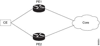
How EVPN core isolation protection works

Summary

The key components involved in the EVPN core isolation protection process are:

  • CE: The device connected to the provider edge router that sends and receives traffic.

  • PE1: A router connected to CE and part of the EVPN-MPLS core network.

  • PE2: Another router in the EVPN/MPLS core network running EVPN with PE1.

  • Core interfaces: Interfaces in the MPLS core network, which can be Gigabit Ethernet or bundle interfaces.

  • Access interface: The interface connecting PE1 to CE, which must be a bundle interface.

  • BGP session: The Border Gateway Protocol session between PE routers used to exchange routing information.

  • Ethernet A-D Ethernet Segment (ES-EAD) routes: Routes advertised by PE1 to signal its presence and services in the EVPN core.

Workflow

Figure 2. EVPN core isolation protection

These stages describe how EVPN core isolation protection works.

  1. The CE connects to PE1, which along with PE2 runs EVPN over the MPLS core network. Core interfaces can be Gigabit Ethernet or bundle interfaces, while the access interface is a bundle interface only.
  2. When the core links of PE1 fail, EVPN detects the failure and isolates PE1 from the core network by shutting down the access interface. This prevents CE from sending traffic to PE1.
  3. The BGP session between PE1 and PE2 also goes down, causing BGP to invalidate all routes advertised by the failed PE1.
  4. When the core interfaces and BGP sessions are restored, PE1 re-advertises its Ethernet Segment routes (ES-EAD), triggering service restoration and reintegration into the core network.

Result

This process ensures that when core links fail, the affected PE1 is isolated to prevent traffic loss or loops, and when connectivity is restored, PE1 seamlessly rejoins the EVPN core network, maintaining service stability and integrity.

Configure EVPN core isolation through peer failure detection

Configure core interfaces within EVPN groups and link these groups to attachment circuits (AC) connected to EVPN single-homing CE devices.

This task applies when setting up EVPN core isolation groups and associating them with bundle interfaces to manage connectivity and redundancy.

Procedure

Step 1

Configure the EVPN core isolation groups and assign core interfaces.

  1. Assign core interfaces for group 42001.

    Example:
    Router# configure
    Router(config)# evpn
    Router(config-evpn)# group 42001
    Router(config-evpn-group)# core interface HundredGigE 0/0/0/24
    Router(config-evpn-group)# core interface HundredGigE 0/0/0/25
    Router(config-evpn-group)#exit
  2. Assign core interfaces for group 43001.

    Example:
    Router(config-evpn)# group 43001
    Router(config-evpn-group)# core interface HundredGigE 0/0/0/26
    Router(config-evpn-group)# core interface HundredGigE 0/0/0/27
    Router(config-evpn-group)#exit

Step 2

Associate the EVPN groups with attachment circuits.

  1. Assign the core-isolation-group 42001 to interface bundle-Ether 42001.

    Example:
    Router# configure
    Router(config)# evpn
    Router(config-evpn)# interface bundle-Ether 42001
    Router(config-evpn-ac)# core-isolation-group 42001
    Router(config-evpn-ac)# exit
  2. Assign the core-isolation-group 43001 to interface bundle-Ether 43001.

    Example:
    Router(config-evpn)# interface bundle-Ether 43001
    Router(config-evpn-ac)# core-isolation-group 43001
    Router(config-evpn-ac)# commit

Step 3

Running configuration of EVPN core isolation through peer failure detection.

Example:

configure
 evpn
  group 42001
   core interface HundredGigE 0/0/0/24
   core interface HundredGigE 0/0/0/25
   !
  group 43001
   core interface HundredGigE 0/0/0/26
   core interface HundredGigE 0/0/0/27
   !
 !
configure
 evpn
  interface bundle-Ether 42001
   core-isolation-group 42001
   !
  interface bundle-Ether 43001
   core-isolation-group 43001
   !
  !

Step 4

Use the show evpn group command to display the complete list of EVPN groups, their associated core interfaces and access interfaces.

The status, up or down, of each interface is displayed. For the access interface to be up, at least one of the core interfaces must be up. The output shows that the core is isolated because the core interfaces are down, bringing down the access interfaces connected to this core.

Example:

Router# show evpn group 
EVPN Group: 42001
  State: Isolated
  Core Interfaces:
     HundredGigE 0/0/0/24: down
     HundredGigE 0/0/0/25: down
     
  Access Interfaces:
     Bundle-Ether42001: down

The output shows that the core is in the Ready state because both the core and access interfaces are UP.

Example:

Router# show evpn group
EVPN Group: 43001
  State: Ready
  Core Interfaces:           
     HundredGigE 0/0/0/26: up
     HundredGigE 0/0/0/27: up
     
  Access Interfaces:
     Bundle-Ether43001: up

The EVPN core interfaces are configured under their respective groups, and these groups are linked to the corresponding attachment circuits. The access interface status depends on the core interfaces’ status; at least one core interface must be up for the access interface to be up.

EVPN cost-out

An EVPN cost-out is a network capability that

  • controls the operational state of bundle interfaces within an Ethernet segment configured with Link Aggregation Control Protocol (LACP)

  • enables placing a node out of service (OOS) without manually shutting down all bundle interfaces on the PE device, and

  • facilitates preparation of the node for reload or software upgrade.

Table 5. Feature History Table

Feature Name

Release Information

Feature Description

EVPN cost-out

Release 24.4.1

Introduced in this release on: Fixed Systems (8700) (select variants only*)

* The EVPN Cost-Out functionality is now extended to the Cisco 8712-MOD-M routers.

EVPN cost-out

Release 24.3.1

Introduced in this release on: Fixed Systems (8200 [ASIC: P100], 8700 [ASIC: P100])(select variants only*); Modular Systems (8800 [LC ASIC: P100])(select variants only*)

* The EVPN Cost-Out functionality is now extended to:

  • 8212-48FH-M

  • 8711-32FH-M

  • 88-LC1-52Y8H-EM

  • 88-LC1-12TH24FH-E

EVPN cost-out

Release 24.2.11

Introduced in this release on: Modular Systems (8800 [LC ASIC: P100]) (select variants only*)

The cost-out node brings down the bundle interfaces on the PE to prepare the node for reload or software upgrade. By costing out a node, the traffic is steered away from the PE without any traffic disruption. This allows you to manage the network traffic effectively while reloading or upgrading a node.

* This feature is supported only on routers with the 88-LC1-36EH line cards.

Traffic redirection using EVPN cost-out for Ethernet segments

The EVPN cost-out process enables seamless traffic redirection in multihomed EVPN environments by gracefully withdrawing a node’s bundle interfaces from service.

  • The router withdraws Ethernet A-D Ethernet Segment (ES-EAD) routes before shutting down the associated bundle interfaces.

  • The PE device notifies the connected CE device to bring down the corresponding bundle member interface.

  • Traffic is automatically steered away from the affected PE node, ensuring no disruption to ongoing services.

  • In a multihoming scenario, any traffic from the CE destined for the Ethernet segment is redirected to a peer PE device.

EVPN cost-out is supported only on Ethernet segments that have manually configured Ethernet Segment Identifiers (ESIs).

How EVPN cost-out works

Summary

The key components involved in the EVPN cost-out process are:

  • CE device: Connects to multiple PE devices and forwards traffic accordingly.

  • PE device: Hosts bundle interfaces on Ethernet segments and controls their operational state.

  • Cost-out command: Controls the operational state of bundle interfaces on PE and CE devices.

  • Startup-cost-in command: Manages timed transition of the node from cost-out to cost-in state after reload.

Workflow

Figure 3. EVPN cost-out

These are the stages of EVPN cost-out.

  1. When the cost-out command is configured on PE1, all bundle interfaces on the Ethernet segment are brought down on PE1. Correspondingly, the related bundle member on the CE is also brought down. This causes the CE to send all traffic for that Ethernet segment to PE2.
  2. To bring the node back into service, the no cost-out command is used. This command brings up all bundle interfaces on the EVPN Ethernet segment on the PE and the corresponding bundle members on the CE.
  3. While the node is in the cost-out state:
    • Adding a new bundle Ethernet segment causes that bundle to be brought down.
    • Removing a bundle Ethernet segment causes that bundle to be brought up.
  4. The startup-cost-in command allows the node to come into service automatically after a specified time following a reload. Initially, the node enters the cost-out state when EVPN initializes and remains so until the timer expires.
  5. If the no startup-cost-in command is executed while the timer is running, the timer stops and the node transitions to the cost-in state.
  6. The cost-out configuration always takes precedence over the startup-cost-in timer. Therefore:
    • If both configurations are present during a reload, the cost-out state is controlled solely by the cost-out command, and the timer is ignored.
    • If the startup timer is running and the cost-out command is configured, the timer stops, and the out-of-service state is controlled exclusively by the cost-out configuration.
  7. If a process restart occurs while the startup-cost-in timer is running, the node remains in the cost-out state and the timer restarts.

Result

This process ensures controlled failover and recovery of traffic between PE devices in an EVPN environment by managing the operational state of bundle interfaces on both PE and CE devices.

Configure EVPN cost-out and startup cost-in timer

Configure EVPN cost-out to bring down a node on a PE device and set the startup cost-in timer to control the node’s startup delay after reload.

Use this task when you need to administratively bring down an EVPN node or delay its startup after a reload to manage network stability and convergence.

Procedure


Step 1

Configure cost-out to bring down the EVPN node on the PE.

Example:

Router# configure
Router(config)# evpn
Router(config-evpn)# cost-out
Router(config-evpn)commit

Step 2

Bring the EVPN node back into service.

Example:

Router# configure
Router(config)# evpn
Router(config-evpn)# no cost-out
Router(config-evpn)commit

Step 3

Configure the startup cost-in timer to delay node startup after reload.

Example:

Router# configure
Router(config)# evpn
Router(config-evpn)# startup-cost-in 6000
Router(config-evpn)commit

Step 4

Running configuration of EVPN cost-out and startup cost-in timer.

Example:


configure
evpn
 cost-out
!

configure
evpn
 startup-cost-in 6000 
!

Step 5

Use the show evpn summary command to verify the cost-out and startup cost-in timer configurations.

Example:

Verify the node cost-out configuration.

Router# show evpn summary
Fri Apr  7 07:45:22.311 IST
Global Information
-----------------------------
Number of EVIs                : 2
Number of Local EAD Entries   : 0
Number of Remote EAD Entries  : 0
Number of Local MAC Routes    : 0
Number of Local MAC Routes    : 5
          MAC                 : 5
          MAC-IPv4            : 0
          MAC-IPv6            : 0
Number of Local ES:Global MAC : 12
Number of Remote MAC Routes   : 7
          MAC                 : 7
          MAC-IPv4            : 0
          MAC-IPv6            : 0
Number of Local IMCAST Routes : 56
Number of Remote IMCAST Routes: 56
Number of Internal Labels     : 5
Number of ES Entries          : 9
Number of Neighbor Entries    : 1
EVPN Router ID                : 192.168.0.1
BGP Router ID                 : ::
BGP ASN                       : 100
PBB BSA MAC address           : 0207.1fee.be00
Global peering timer          :      3 seconds
Global recovery timer         :     30 seconds
EVPN cost-out                 : TRUE
      startup-cost-in timer   : Not configured


Verify the no cost-out configuration.


Router# show evpn summary
Fri Apr  7 07:45:22.311 IST
Global Information
-----------------------------
Number of EVIs                : 2
Number of Local EAD Entries   : 0
Number of Remote EAD Entries  : 0
Number of Local MAC Routes    : 0
Number of Local MAC Routes    : 5
          MAC                 : 5
          MAC-IPv4            : 0
          MAC-IPv6            : 0
Number of Local ES:Global MAC : 12
Number of Remote MAC Routes   : 7
          MAC                 : 7
          MAC-IPv4            : 0
          MAC-IPv6            : 0
Number of Local IMCAST Routes : 56
Number of Remote IMCAST Routes: 56
Number of Internal Labels     : 5
Number of ES Entries          : 9
Number of Neighbor Entries    : 1
EVPN Router ID                : 192.168.0.1
BGP Router ID                 : ::
BGP ASN                       : 100
PBB BSA MAC address           : 0207.1fee.be00
Global peering timer          :      3 seconds
Global recovery timer         :     30 seconds
EVPN cost-out                 : FALSE
      startup-cost-in timer   : Not configured


Verify the startup-cost-in timer configuration.


Router# show evpn summary
Fri Apr  7 07:45:22.311 IST
Global Information
-----------------------------
Number of EVIs                : 2
Number of Local EAD Entries   : 0
Number of Remote EAD Entries  : 0
Number of Local MAC Routes    : 0
Number of Local MAC Routes    : 5
          MAC                 : 5
          MAC-IPv4            : 0
          MAC-IPv6            : 0
Number of Local ES:Global MAC : 12
Number of Remote MAC Routes   : 7
          MAC                 : 7
          MAC-IPv4            : 0
          MAC-IPv6            : 0
Number of Local IMCAST Routes : 56
Number of Remote IMCAST Routes: 56
Number of Internal Labels     : 5
Number of ES Entries          : 9
Number of Neighbor Entries    : 1
EVPN Router ID                : 192.168.0.1
BGP Router ID                 : ::
BGP ASN                       : 100
PBB BSA MAC address           : 0207.1fee.be00
Global peering timer          :      3 seconds
Global recovery timer         :     30 seconds
EVPN node cost-out            : TRUE
        startup-cost-in timer : 6000

The EVPN node is administratively brought down or brought up as needed, and the startup cost-in timer controls the delay before the node becomes active after a reload.