Unified Messaging
Available Languages
Table Of Contents
Components of a Unified Messaging System
Subscriber Does Not Answer Call
Caller Leaves a Message for a Subscriber
Subscriber Is Notified to Retrieve Messages
Subscriber Calls the UM Server to Retrieve Messages
Inbound Fax Message to a Subscriber
Printing a Fax Message from a Subscriber Mailbox to an Alternate Fax Number
Overall uOne Protocol Flow Sequence
Deploying Unified Messaging Services in a Service Provider Environment
Add Greeting and Fax Administrators
Add Organizational Unit UMSA Administrators and Subscribers
Deploying Unified Messaging for Dial Internet Access
Deploying Unified Messaging for Dedicated Internet Access
Sharing uOne Resources at the POP
uOne Server Redundancy and Load Balancing
Fax Gateway (Off-Ramp) Redundancy and Load Balancing
H.323 Gateway Redundancy and Load Balancing
A Fully Redundant Configuration
Unified Messaging Configuration Examples
Interoperability with Cisco and NetSpeak Gatekeepers
NetSpeak Gatekeeper Configuration Example
Cisco AS5300 Gateway Configuration Example
Cisco Gateway and Gatekeeper Configuration for Two-Stage Dialing
Unified Messaging
Version History
1
05/15/2001
This document was created.
2
06/27/2001
Incorporated editorial comments.
Unified Open Network Exchange (uOne) is an enhanced, IP-based software solution that gives subscribers the ability to receive voice mail, e-mail, and fax messages in a single mailbox that can be accessed via the phone or from a desktop browser or e-mail client.This document discusses various unified messaging concepts and features that apply to the Cisco uOne unified messaging (UM) solution. It also provides high-level examples showing how to deploy UM in different service provider and enterprise environments.
This document contains the following sections:
•
Deploying Unified Messaging Services in a Service Provider Environment
•
•
•
•
Unified Messaging Overview
Unified Communications (UC) integrates the two separate worlds of phone and Internet over a single unified network. As mentioned, Unified Open Network Exchange (uOne) is an enhanced, IP-based software solution that gives subscribers the ability to receive voice mail, e-mail, and fax messages in a single mailbox that can be accessed via the phone or from a desktop browser or e-mail client.
Unlike time division multiplex(TDM)-based proprietary messaging solutions, the Cisco UC platform is built on Open Packet Telephony (OPT), a Cisco standards-based, open-protocol voice and data architecture. The standards-based services platform is designed to carrier-class specifications, providing scalability to support millions of subscribers. It combines synchronous and asynchronous message types, including Voice over IP (VoIP), Internet fax, store and forward voice mail, and e-mail under a common message store and directory. This arrangement eliminates the need to synchronize disparate message stores and directories, such as different voice mail and e-mail systems, and dramatically reduces operational and maintenance costs. Competitive products that use old-world publich swtiched telephone networks (PSTNs) cannot offer this level of integration or scalability.
Unified Messaging Features
The features of a unified messaging solution are discussed in the following sections:
Voice Messaging over IP
Voice messaging over IP allows service provider subscribers to check and access messages from any phone and to perform the following tasks:
•
•
•
•
•
•
•
E-Mail Messaging over IP
E-mail messaging over IP allows subscribers to access e-mail messages from a phone and to perform the following tasks:
•
•
•
•
E-mail messaging over IP supports both Point of Presence (POP) and Internet Messaging Access Protocol (IMAP) clients.
Fax Messaging over IP
Fax messaging over IP allows subscribers to receive faxes anywhere by redirecting fax messages from their UM mailbox to a nearby fax machine. Fax messaging over IP also enables subscribers to perform the following tasks:
•
•
•
•
•
Single Number Reach
The Single Number Reach feature improves accessibility by providing a single phone number that callers use to locate a subscriber in multiple locations. With Single Number Reach, callers can perform the following tasks:
•
•
With Single Number Reach, subscribers can perform the following tasks:
•
•
•
Components of a Unified Messaging System
uOne is built on a distributed agent platform (DAP), an open systems distributed computing environment that permits easy integration of new, nonproprietary voice and information processing technologies. DAP is based on a client/server model and consists of several components networked to provide all the functions of a unified messaging system.
The architecture is a distributed, object-based framework providing native support for all major industry standards such as Lightweight Directory Access Protocol (LDAP), IMAP4, Simple Mail Transport Protocol (SMTP)/Multipurpose Internet Mail Extensions (MIME), Voice Profile for INternet Messaging (VPIM), HTTP/HTML, and support for centralized Signaling Network Management Protocol (SNMP) management and web-based administration. The Cisco uOne applications reside on a gateserver that interfaces with the circuit-switched network through a Registration, Admission, and Status (RAS) gateway to any telephone, cellular phone, or fax machine. Gateserver applications then communicate over the IP network to directory services, media services, and management services. This arrangement allows uOne and other enhanced services applications to communicate with anyone, anywhere, using the IP network.
Figure 1 shows a complete unified messaging solution based on a three-tiered model of access services, application services, and back-end services.
Figure 1 The Unified Messaging Three-Tier Model
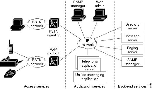
The following sections describe the components of a unified messaging system:
Access Services
Access services provide access to application services and the front-end user interface of the unified messaging system. Subscribers can access messaging services with traditional telephony equipment, like phones and fax machines, or by workstations connected to an IP network. Access services provide call recognition and routing, media translation, and telco signaling.
Access services include the following components:
•
•
A gateway is an H.323 component that facilitates translation among various transmission formats and communication procedures (signaling). It is responsible for call setup and teardown on both the network and PSTN sides.
A gatekeeper provides call control services to the H.323 endpoints. The main functions of a gatekeeper in an H.323 network are as follows:
•
•
•
Application Services
Application services provide all the messaging logic required for the following features:
•
•
•
•
•
•
Application services are the endpoints for all H.323 calls into and out of the unified messaging system. Figure 2 shows how application services are laid out.
Figure 2 Application Services
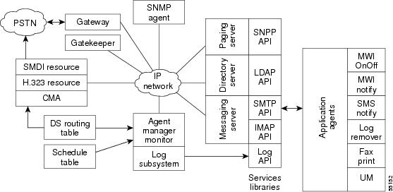
Application services have three major components: Agent Communications Broker, Call Control/Media Control Agent, and SNMP Agent.
The Agent Communications Broker (ACB) is a set of distributed software modules that provides communication services to other Directory Access Protolc (DAP) agents. The ACB includes the following features:
•
•
•
•
•
•
The call control/media control agent (CMA) supports call control, media control, and the media resources. It uses H.323 call control signaling to accept, drop, and manage calls from an H.323 gateway or gatekeeper. It uses RAS to register with an H.323 gatekeeper, and it provides dual tone multi-frequency (DTMF) detection services. The CMA also provides media services such as playing, recording, and deleting messages.
The CMA and the ACB must reside on the same gateserver. The CMA uses dialed number identification service (DNIS) or redirected number (RDN) as the token to search the domain services routing table and determine which application will handle the request.
LDAP Directory Services
Lightweight directory access protocol (LDAP) is a directory service protocol that runs over TCP/IP. A directory is like a database but it usually contains more descriptive, attribute-based information. Directory information is generally read much more often than it is written. Consequently, directories do not usually use the same complicated transaction or roll-back schemes that regular databases do for high-volume, complex updates. Instead, directories are tuned to give quick response to high-volume lookup or search operations. They can replicate information widely and increase availability and reliability while reducing response time. The basic function of a directory service is to allow you to store and retrieve information about your enterprise or subscribers. You can retrieve the information by either directly searching for that information, or by searching for related, but more-easily remembered information, such as a name.
The LDAP directory service model is based on entries. An entry is a collection of attributes that has a name, called a distinguished name (DN), which is a unique reference for the entry. In LDAP, directory entries are arranged in a hierarchical tree-like structure that reflects, for example, political, geographic or organizational boundaries. LDAP defines operations for interrogating and updating entries in the directory—for adding and deleting entries from the directory, changing existing entries, and changing the names of entries. LDAP query requests permit a portion of the directory to be searched for entries that match certain criteria specified by a search filter. Information can be requested from each entry that matches the criteria.
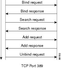
LDAP is based on the client/server model and uses TCP as its transport protocol. One objective of LDAP is to minimize the complexity of clients, to facilitate large-scale deployment and hence scalability. Each Directory Server instance can support millions of entries and thousands of queries per second. By using replication and referrals, the Directory Server can be scaled to support even the largest of enterprises and subscriber bases, including multinational corporations and very large internet service providers (ISPs). Figure 3 shows a typical LDAP session call flow.
Figure 3 LDAP Session Call Flow
Unified messaging uses the directory server primarily to store and retrieve user profile information. You perform administrative tasks on the directory server by using vendor-supplied tools, like the Netscape console and admin server. UM subscribers interact with the directory server using Cisco web-based tools such as Personal Mailbox Administration (PMA), which permits subscribers to administer their personal preferences. Unified Messaging System Administration (UMSA) is the Cisco web-based tool that you can use to create new classes of service, add subscribers, manage broadcast lists, and manage user mailboxes.
You can use communities of interest (COI) as a mechanism to split a large directory into smaller, more manageable directories, each of which has its own access control and well-defined search base that restricts the view of the directory. COI usually defines a subscriber group that subscribes to a customized set of services under a single administrative authority. Service providers can use the same set of shared resources to create multiple communities of interest. The COI is based on the directory tree structure on the directory server and is defined by a specific node in the tree. Users within a COI have restricted visibility to everything below their node in the hierarchical directory tree structure.
Referrals in LDAP are a redirection mechanism that is used by a directory service to scale the service beyond the millions of users that can be supported with a single server. When an LDAP client queries a directory service and the query does not match any of the directory suffixes it supports, the server can return a referral to the client, requesting it to direct the query to a different LDAP server. Upon receipt of the referral, the client reformats the original LDAP request to fit the boundaries set by the referral, and reissues the request to the new server. Referrals are not returned if the directory names do not match, or if the client attempts to modify an entry that does not exist.
LDAP version 3 supports smart referrals, which allow you to map your directory entries to specific LDAP URLs. Smart referrals permit a directory server to refer the query to another server that services the same name space, or to refer it to a different name space within the same server. With smart referrals, if a client attempts to modify a directory entry and is referred elsewhere, the client will reformat the modification request to fit the boundaries set by the referral, and reissue the request to the new server. If the client has sufficient privileges, the operation is performed without the user ever knowing that the activity occurred on a remote server.
The Cisco unified messaging server uses LDAP version 2 APIs. The server does not process any LDAP referrals because there is no easy way to permit directory entry modification across multiple directory servers with referrals in LDAP version 2. The current version of UM will not support a model with multiple LDAP servers even though it is possible to handle directory changes by processing smart referrals. However, the unified messaging application is fully compatible with both versions of LDAP in the single directory service model.
Messaging Server
Messaging server is a messaging service that provides open, standards-based, flexible, cross-platform e-mail and messaging solutions, scalable to many thousands of simultaneous users. Messaging server provides the UM application with a common message store and allows access to its message store by standard Internet protocols such as IMAP4, POP3 and HTTP. Messaging server is an LDAP client, and uses the directory server as the centralized store for mail-user account storage, authentication, and mail routing control. The messaging server also provides a facility for specialized HTTP service for web-based e-mail. HTTP clients send mail to the specialized HTTP service, which then transfers the requests to a mail transfer agent.
The Cisco unified messaging application uses SMTP to store e-mail, voice mail, and fax mail messages on the common message store provided by the messaging server. The messages are stored in MIME format. UM subscribers use IMAP4, POP3, or HTTP to retrieve these messages from the message store.
Messaging servers use SMTP to accept and route messages. The following steps summarize how the messaging server accepts and routes a message:
1.
2.
3.
a.
b.
c.
d.
e.
To retrieve a message, the client must know the IP address of the messaging server, establish a connection to the server, then retrieve the message using one of the retrieval protocols: POP3, IMAP4, or HTTP. The following steps summarize how the client retrieves a message:
1.
2.
3.
4.
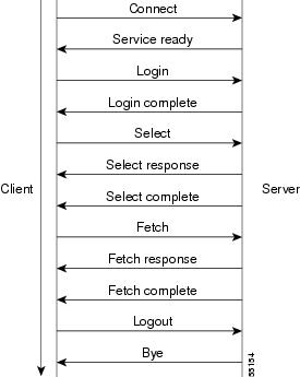
uOne uses IMAP4 for storage and retrieval of messages from the messaging server. A typical IMAP session is summarized in Figure 4.
Figure 4 IMAP Session Call Flow
Typical uOne Call Flows
Call flows typical of uOne operation are described in the following sections:
•
•
•
•
•
•
•
Subscriber Does Not Answer Call
When someone calls a subscriber and there is no answer, the call is forwarded to the gateserver. When the local exchange carrier (LEC) switch detects an incoming call that is destined for a busy or nonanswering party, the switch formulates a Q.931 setup message with the redirected number (RDN) field set to the original destination number, and sends it to the gateway. The called-party number of the setup message is set to one of the DNIS access numbers of the gateway. The original called number is then the RDN, and the number that was called to access the server is the DNIS. Whenever the RDN field is populated, the UM application uses it to retrieve (using LDAP) the subscriber profile from a directory server. If there is a matching subscriber, UM retrieves and plays the subscriber's personal greeting. Figure 5 shows an example of how this process works.
Figure 5 Retrieve Subscriber Personal Greeting
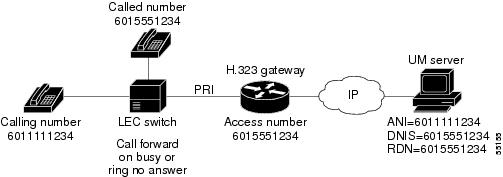
In this example, the presence of RDN indicates a call to the subscriber. The UM searches for the subscriber profile using 6015551234, retrieves it, and plays the personal greeting.
When a subscriber calls the UM server to access messages, automatic number identification (ANI) is set to the calling number, DNIS is set to the called number, and RDN is not populated. In this case, UM plays the general welcome message and requests the caller phone number and personal identification number (PIN). A subscriber calling from his or her own phone simply can press the pound (#) key, in which case UM uses the ANI to retrieve the subscriber profile, as shown in Figure 6.
Figure 6 ANI Profile Retrieval
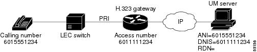
In this example, an unpopulated RDN field indicates a call from the subscriber to retrieve messages. The UM requests that the subscriber enter his or her phone number or simply press #. If the subscriber enters a phone number, it is used in a directory search (LDAP). If the subscriber enters #, 6015551234 is used to search the directory for his or her profile.
Caller Leaves a Message for a Subscriber
When someone calls a subscriber phone number and does not get an answer, the subscriber's switch forwards the call to the Cisco AS5300 gateway. Figure 7 shows how the messaging server accepts and routes a message to the subscriber.
Figure 7 User Calls and Leaves a Message
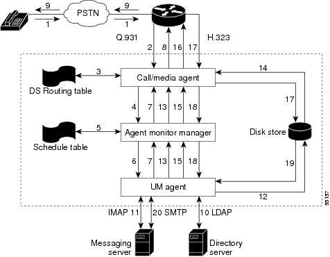
The following describes each step in the call flow diagram shown in Figure 7:
1.
2.
3.
4.
5.
6.
7.
8.
9.
10.
11.
12.
13.
14.
15.
16.
17.
18.
19.
20.
Subscriber Is Notified to Retrieve Messages
For a message waiting indicator or stutter dial tone, the gateserver must have an EIA/TIA-232 connection to a switch that has access to the telephone handset. For paging services, a Hylafax Simple Network Paging Protocol (SNPP) server must be installed and accessible to the gateserver. Figure 8 shows the subscriber notification process.
Figure 8 The Subscriber Notification Process
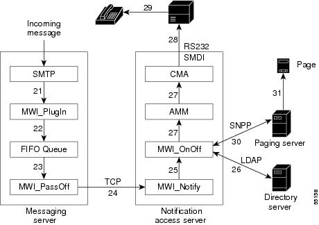
The following describes each step in the subscriber notification process flow diagram in Figure 8:
21.
22.
23.
24.
25.
26.
27.
28.
29.
30.
31.
Subscriber Calls the UM Server to Retrieve Messages
After being notified by an MWI or a page, the subscriber can retrieve messages. Figure 9 shows how the subscriber retrieves messages.
Figure 9 Subscriber Calls to Retrieve Messages
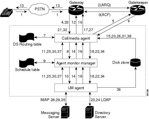
The following describes each step in the message retrieval flow diagram shown in Figure 9:
1.
2.
3.
4.
5.
6.
7.
8.
9.
10.
11.
12.
13.
14.
15.
16.
17.
18.
19.
20.
21.
22.
23.
24.
25.
26.
27.
28.
29.
30.
31.
32.
33.
34.
35.
36.
37.
38.
Inbound Fax Message to a Subscriber
The gateserver does not participate in handling incoming fax messages. When a fax account is created on the UM server, it creates an alias file on the messaging server, where it maps the subscriber fax number to his or her e-mail address. This alias is used in Step 4 of the fax delivery process described later in this section.
With the Store and Forward Fax feature, the Cisco AS5300 acts as an on-ramp gateway, which receives faxes from end users and converts them into Tag Image File Format-Fax (TIFF-F) files. It attaches this TIFF-F file to a MIME e-mail message and forwards it to a designated SMTP server where the e-mail is stored. Figure 10 shows how the fax delivery process works.
Figure 10 The Fax Delivery Process
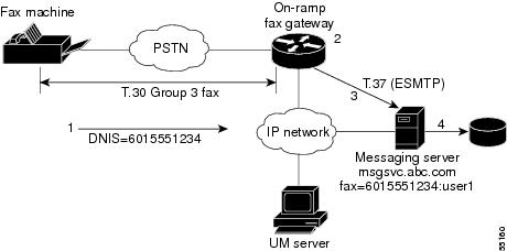
The following describes each step in the fax delivery process flow diagram shown in Figure 10:
1.
2.
3.
4.
Printing a Fax Message from a Subscriber Mailbox to an Alternate Fax Number
After successfully logging in using a telephone, the subscriber can choose to retrieve faxes or e-mail messages containing faxes and redirect these messages to another fax number to be printed. Figure 11 shows how the subscriber retrieves fax messages by printing them to an alternate fax number.
Figure 11 Printing to an Alternate Fax Number
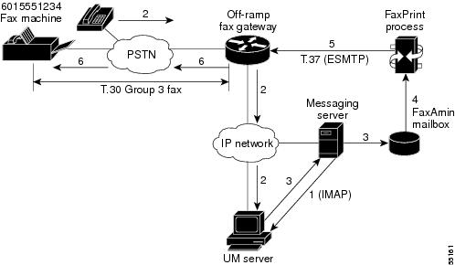
The following describes each step in the redirect fax printing process flow diagram shown in Figure 11:
1.
2.
3.
4.
5.
6.
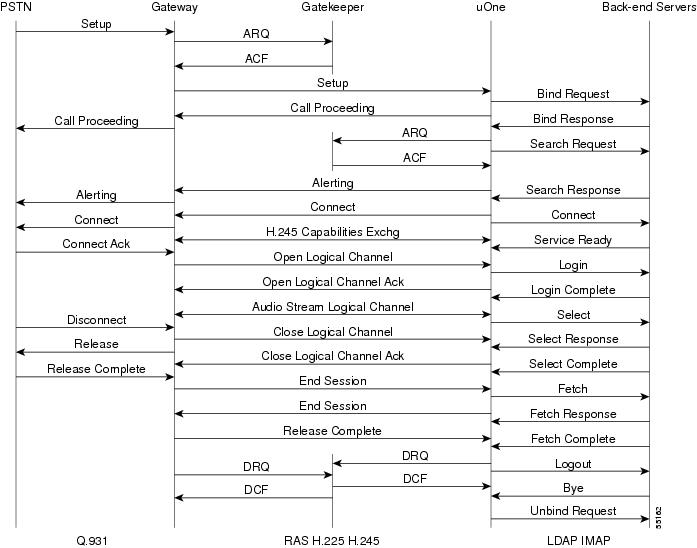
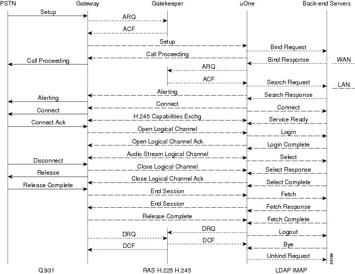
Overall uOne Protocol Flow Sequence
Figure 12 summarizes the overall uOne protocol flow sequence.
Figure 12 Overall Protocol Flow Sequence
Deploying Unified Messaging Services in a Service Provider Environment
This section describes the general process of deploying unified messaging services in a service provider environment. This process typically includes the steps described in the following sections:
•
•
Service providers typically have a large set of users with varying requirements. They also provide Internet service to a number of small corporations. Unified messaging services can be deployed across the entire service provider network and sold at different levels to individual users and corporations. A typical deployment in a service provider environment would be decentralized (as shown in Figure 13) to provide for local-number access to services.
Ideally, there is one or more gateservers per point of presence (POP), with their own messaging servers connected locally. However, they all share a common centralized directory service. From a unified messaging point of view, a totally self-contained POP has a gateserver, a messaging server (for local message store), an H.323 gateway (for local access to the gateserver), and an access gateway that allows users to dial in to the service provider network.
Figure 13 ISP Deployment Scenario
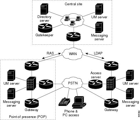
In this scenario, LDAP and RAS are the only UM-related protocols that use the WAN. E-mail messages to the user are relayed (using SMTP) to messaging servers located at each POP. Depending on the subscriber base at each POP, multiple gateservers can share the same central messaging server or one that is located at one of the POP sites.
Initially, you can provide service to your subscribers at the central site, then add messaging servers and gateservers at POP installations as the subscriber base grows. If subscribers travel from one POP to another, they can still access their services with a local call. The local gateserver will be able to service all requests, but because the messaging serverof the subscribers is not local, they might notice a small degradation in service, depending on network bandwidth availability.
To subscribers who travel out of your service area, you can provide 800-number access to a gateway at the central site for an additional fee. In the scenario described, the distributed architecture allows any gateserver to service any subscriber because they all have access to a common directory server. The distributed architecture provides for complete redundancy and also helps with maintenance of the gateservers.
After the services are deployed, they can be used to support many different COIs, enabling you to sell different levels and classes of service to individual subscribers, corporations, and resellers.
To deploy unified messaging services in a service provider environment, perform the following tasks, which are described in the sections that follow:
•
•
•
•
•
•
•
Determine Optimal Design
A typical service provider services both individual subscribers (with dial Internet access) and corporations, with their own dedicated Internet access solutions. The decision where to place various components of a uOne solution depends on the subscriber base, the available bandwidth, and the quality of the unified messaging services offered. The various network components associated with a uOne solution affect service quality in different ways. The following sections describe the major components, their main functions, and how the components affect service quality.
Gateserver
In the unified communication solution, the gateserver is the termination point for an H.323 connection. Depending on its proximity to the H.323 gateway, and the available bandwidth between the gateserver and H.323 gateway, the gateserver affects call setup times and voice quality. Other factors that influence the performance of the gateserver are the number of simultaneous calls that can be handled, and available resources such as memory and CPU.
Directory Server
Directory services are used to authenticate, store, and retrieve subscriber profile information. Directory services directly influence authentication and message response times. Authentication time is the time a user must wait for the system to respond after a user ID and PIN have been entered. Directory services are also used to store subscriber mailbox and login information so that uOne can retrieve subscriber messages. Login information must be retrieved from the directory server to be able to log in to the messaging server and retrieve the message. Message response time is the time a subscriber must wait to hear the message after the message has been selected. We recommend that directory services be centralized and deployed at the core because all uOne servers in an ISP share the same directory.
Messaging Server
The messaging server is used to store and retrieve personal greetings, and voice, e-mail, and fax messages. It directly affects message response time and greeting response time. Greeting response time is the time the system takes to retrieve and play a personal greeting after it has determined which greeting to play. Other factors that can influence the performance of a messaging server are the size of the subscriber base that is served by the server, and available resources such as CPU and memory.
H.323 Gateway
The H.323 gateway serves as the protocol translator between the PSTN and the H.323 networks. Depending on the proximity of the unified messaging system to the subscriber base, subscribers might not have local number access to it. The gateway directly affects call setup times and voice quality.
H.323 Gatekeeper
Primarily, the gatekeeper determines which gateserver will handle an incoming call. It has a direct influence on call setup times.
Create Multiple COIs
The concept of COI involves taking a large set of users and logically grouping them into smaller communities under a single administrative authority. As single administrative authority allows the same unified messaging service infrastructure to be used by multiple communities at the same time, and permits delegation of administrative tasks to the unified messaging administrators for that community. Every administrator can customize its own greetings, provide different classes of service, and perform other administrative tasks within their own COI. A COI translates to a point in the directory tree on a directory server. Figure 14 illustrates a sample directory tree for a typical service provider.
Figure 14 Sample Directory Tree
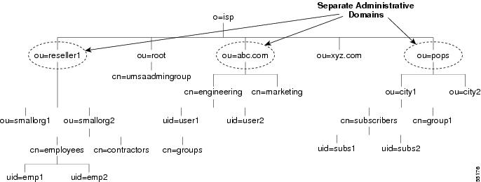
Data in a directory is hierarchical, and is represented as attribute-data pairs. The attributes used in this directory example are as follows:
•
•
•
•
The top level "o=isp" and the administrative account are created at installation time. The top-level administrator (admin) can create more organizations and organizational units, groups, and users. uOne requires an organizational unit called "root" and a group under "root" for Unified Messaging System Administration (UMSA) administrators. The administrator accesses the LDAP directory server using a web interface at http:\\directoryServer:2500.
Once logged in as the admin, you can create more organizational units and groups, as shown in Figure 14. You should refer to the directory server user guide for details on how to create additional organizational units, groups and users. Creating organizational units, groups, and a few sample users will create database entries with directory branch points.
If you export the directory, the resulting LDAP Data Interchange Format (LDIF) file will have the format of individual entries in the directory database. You can then uses this LDIF file as a template for creating a large number of entries in the directory. For example, you can use an existing subscriber database as a source to create a large number of directory entries by using a scripting language to automate the creation of the LDIF file, which can then be imported into the directory.
You can also use the bulk add tool that comes with the UM server to add a large number of entries to your directory. Once again, you should refer to the directory user and deployment guides that came with the directory server for details about directory design.
Define Classes of Service
A CoS defines a common set of unified communication services for a group of subscribers that is administered by a central authority. Subscriber groups use COSs to bundle various feature sets into distinct packages that facilitate administration of common features. A COS is unique within a COI and is identified by a number (for example, COS=1). COSs are defined by identifying sets of features that you can market as different levels of services to subscribers and resellers.
In the example in Figure 15, "DL" stands for directory listing, "DL Entries" specifies how many listings are permitted per list, and "Number of DLs" specifies the maximum number of lists that the user can create. Because a CoS is unique per organizational unit, it is possible to have the same COS number under different organizational units.
Figure 15 Classes of Service
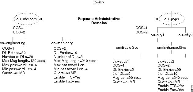
Two CoSs are defined for subscribers at POP sites. Basic services include voice mail and e-mail, with each voice message restricted to a maximum length of 90 seconds. Enhanced services include basic services and permit fax and Text To Speech (TTS) services, and increase the maximum length of voice messages to 240 seconds. Also, enhanced services subscribers can create more and larger distribution lists.
Every organizational unit needs one COS defined for each feature set being offered to users. You can define COSs by using the web-based administration tool under "COS Administration." The entry in the "DN" field in "add a new COS" associates the COS with an organizational unit. In the Figure 15 example, the Distinguished Name (DN) entry for abc.com would be "ou=abc.com,o=isp." The complete entry is:
Entry DN: ou=abc.com, o=ispClass of Service ID: 1Class of Service Name: EngSvcSearch Base: ou=abc.com,o=ispPersonal Access UM Ini File Name: UM.iniYou should refer to the UM administrator guide for more details.
Add Greeting and Fax Administrators
The greeting administrator account is a special mailbox used to store personal greetings and distribution list names for subscribers. The greeting administrator is identified by msgadmin@<organizational unit name>. Each organizational unit requires its own greeting and fax admin accounts and can have more than one of each.
Every subscriber account has a greeting and a faxadmin associated with it. When a subscriber is added to the system, a set of folders is added to the greeting admin account to store the subscriber personal greetings and distribution list information. These folders are separate from the subscriber message mailbox, which stores their voice, fax, and e-mail messages. When a subscriber first logs in to the system and records a personal greeting, the greeting is stored in a folder under the subscriber greeting administrator. Figure 16 shows how the centralized greeting admin works.
Figure 16 Protocol Flows for Centralized Greeting Admin
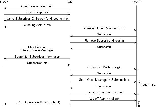
When a call comes in for a subscriber, a personal greeting needs to be played to the caller. Using IMAP, the greeting is retrieved from the greeting admin account where it is stored. However, the voice mail message left by the caller will be stored in the subscriber mailbox, which can be accessed by an e-mail client. Centralized greeting admins and local subscriber message stores will result in personal greetings being retrieved across the WAN, but voice messages being stored and retrieved locally for subscribers at POPs. In Figure 16, the only traffic local to the POP is the storage of voice messages in the subscriber mailbox. If you created the greeting and faxadmin accounts on the local message store to service all local subscribers, all IMAP traffic will be local to the POP. The greeting and faxadmin accounts can be added using UMSA under "Global Administration." We recommend that you create a greeting and faxadmin account on a messaging server to service all subscribers that have a message store on that server.
Add Organizational Unit UMSA Administrators and Subscribers
Each organizational unit requires a UMSA administrator that will manage its COI. UMSA administrators have add, change, and delete privileges over subscribers and COSs within their COI. These unique admin accounts have privileges within their own COI and are added as subscribers. Any subscriber can be made a UMSA administrator by adding the subscribers to the UMSA administrator group created under ou=root.
UMSA administrators can add subscribers within their own COI using the web-based UMSA tool. While adding subscribers, administrators can select the messaging server and greeting and fax admins that service the subscriber. All messaging servers known to the LDAP directory service, and the defined greeting and fax admins, are listed in the drop-down menu on the web interface. Selecting the appropriate message store and greeting admin is an important consideration when adding new subscribers because they define the message store for personal greetings and faxes and the message store for incoming e-mail, voice mail, and fax.
Deploy Fax Services
When you enable fax services for subscribers, the subscribersare assigned a fax number where incoming faxes will be accepted and stored in their mailbox. Subscribers also have the ability to redirect e-mail and fax messages from their mailboxes to any fax machine. Depending on the volume of subscribers wanting fax services, fax gateways can be local to the POP or centralized.
Fax services are described in detail in the integrated solutions document titled Fax Services.
Deploying Unified Messaging for Dial Internet Access
Four scenarios for deploying unified messaging for dial Internet access, along with associated call flows are described in the following sections:
Completely Centralized
The completely centralized configuration is a good starting point for deployment of uOne services where, except for an H.323 gateway to provide local-number access, all other uOne components are centrally located at your core network. A completely centralized configuration is an acceptable model when the subscriber base is small and services are just being introduced. Figure 17 shows an example of a completely centralized unified messaging deployment; Figure 18 shows the flow sequence for this deployment.
Figure 17 Completely Centralized Deployment
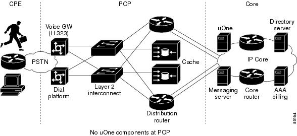
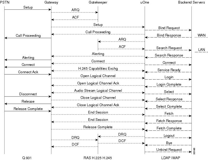
Figure 18 Completely Centralized Flow Sequence
Partially Centralized
As the subscriber base at a POP site grows, we recommend that a uOne server be dedicated to servicing the site while still maintaining back-end services at the core. Deploying the uOne server in this way improves call setup times and voice quality and is easy to deploy. The server at the POP will now service existing subscribers from the POP using the core uOne server because the gatekeeper can be configured to forward calls to the POP to a local server. No other changes to the configuration or user profile information will be necessary. Figure 19 shows an example of a partially centralized unified messaging deployment; Figure 20 shows the flow sequence for this deployment.
Figure 19 Partially Centralized Deployment
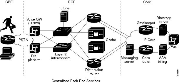
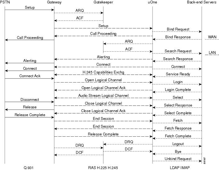
Figure 20 Partially Centralized Flow Sequence
More Distributed
As the subscriber base at a POP site continues to grow, we recommend that you dedicate a messaging server to service the site. Dedicating a messaging server greatly improves message response times and voice quality because all messages are stored and retrieved locally across the LAN. However, your subscribers could notice a slight increase in message response times if they attempt to access their messages from another POP site because the messages must be retrieved across the WAN from the messaging server at their home site. Figure 21 shows an example of this unified messaging deployment; Figure 22 shows the flow sequence for this deployment.
Figure 21 More Distributed Deployment
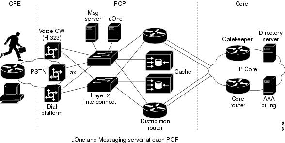
Figure 22 More Distributed Flow Sequence
Completely Distributed
In a completely distributed deployment, everything but directory services is moved to the local POP. Except for authentication and retrieving user profile information, all the other services are local to the POP. Because the gatekeeper is local as well, call setup times are very good and service quality is at its best. Each POP will have its own zone and can be designed for fault tolerance by using redundant gateservers and redundant gatekeepers running HSRP. In normal operation, both gateservers have equal priority and share the call load on a per-call basis. (Call balancing and redundancy are discussed later in this document.) Figure 23 shows an example of a completely distributed unified messaging deployment; Figure 24 shows the flow sequence for this deployment.
Figure 23 Completely Distributed Deployment
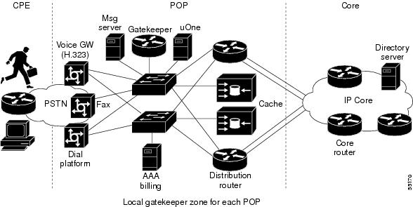
Figure 24 Completely Distributed Flow Sequence
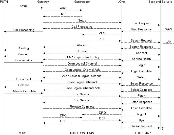
Table 1 summarizes the qualities of each of the described dial Internet access deployment scenarios.
Table 1
Deployment Summary
•
•
•
•
Deploying Unified Messaging for Dedicated Internet Access
Three scenarios for deploying unified messaging for dedicated Internet access are described in the following sections:
•
Sharing uOne Resources at the POP
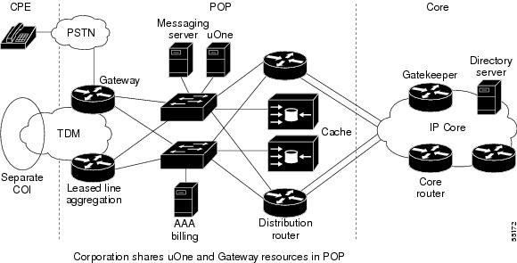
Small and large corporations use dedicated lines to the ISP for Internet access. A separate COI is set up for each corporation, and administrative authority for this COI is delegated to a system administrator within the organization. The corporation can then set up accounts for its employees on a trial basis and share uOne resources at the POP to which they connect. Employees with unified messaging accounts can access their messages by calling the POP site. Figure 25 shows an example of sharing uOne resource at the POP to deploy unified messaging.
Figure 25 Shared POP Gateway
Local Gateway
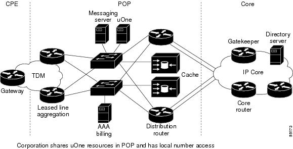
As more users within the organization use unified messaging services, it is more economical for the corporation to have its own local gateway, especially if users must pay toll charges to access the services at a POP site. Figure 26 shows an example where the corporation has its own local gateway.
Figure 26 Local Gateway
Dedicated uOne Resources
When the subscriber base within the organization grows even more, the growth justifies dedicated uOne resources to handle all unified communication services. In this case, the uOne server is at the customer site, and messaging servers need to be integrated into existing mail servers. However, directory services is centralized at the core, and billing records can be collected at the POP site or at the core. Figure 27 shows an example of dedicated uOne resources to deploy unified messaging.
Figure 27 Dedicated uOne Resources

Redundancy and Load Balancing
This section describes how to provide redundancy and load balancing for unified messaging services and includes the following sections:
•
•
•
•
uOne Server Redundancy and Load Balancing
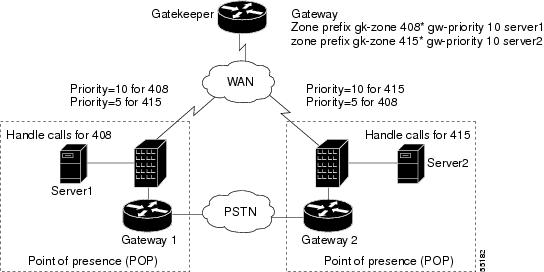
Gateservers register themselves as gateways with an H.323 gatekeeper. If multiple gateservers register with the same gatekeeper, and they can all handle any service call, the gatekeeper automatically rotates the calls among all the registered gateways of equal priority. Figure 28 shows an example of load balancing between two UM servers, Server1 and Server2:
Figure 28 uOne Server Redundancy and Load Balancing
In Figure 28, calls are load-balanced between Server1 and Server2 because they have equal priority to handle calls starting with "415." However, because all calls are not of the same duration, load balancing is only on a per-call basis. If one of the UM servers is down, it loses its registration with the gatekeeper and the other server handles all incoming calls.
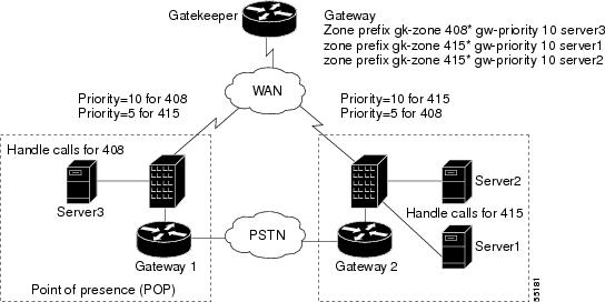
Based on the geographic location of a UM server, you can configure the gatekeeper with different levels of priority for each gateserver, as illustrated in Figure 29.
Figure 29 uOne Server Redundancy Across POPs
Server1 has been assigned a priority of 10 for handling calls to area code 408. Server2 has priority 10 for area code 415. The default priority for a gateway is 5. If one of the servers fails, the server with a lower priority will take over.
Even though a server in one geographic location can service a call in another geographic location, the server still needs to access the message store for the subscriber, which might be local to the POP. Access to this message store is across the WAN, so the subscriber might notice a slight degradation in service depending on existing traffic loads and bandwidth across the WAN.
Please note that there is no redundancy for active calls being currently serviced by a uOne server. If the server becomes unavailable, another uOne server will handle new incoming calls but existing calls will be disrupted and will need to be reestablished by the caller.
Fax Gateway (Off-Ramp) Redundancy and Load Balancing
By using the Cisco IOS Server Load Balancing (IOS SLB) feature, you can configure multiple fax gateways at a POP site to balance the outbound fax load and provide redundancy and load balancing as shown in Figure 30. IOS SLB is a Cisco IOS-based feature that provides load balancing among multiple servers.
Figure 30 Redundancy and Load Balancing with IOS SLB
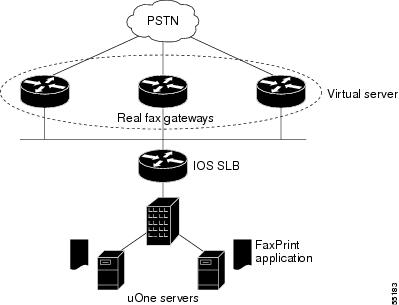
A virtual server is a group of real fax gateways that can handle outbound fax calls. The virtual server is assigned an IP address, which is also configured as a secondary address on each of the constituent fax gateways. The uOne faxprint process is configured to connect to this virtual IP address in the faxprint.ini and dialmap.ini files.
When the faxprint process initiates a connection to the virtual IP address, the IOS SLB software chooses a real fax gateway to service this connection based on the configured load-balancing algorithm. IOS SLB software tracks each connection attempt to a fax gateway. If several consecutive TCP "SYN" open connections are not acknowledged, the session is assigned to a new fax gateway.
The number of connection attempts before reassigning the session is configurable. Every failed connection attempt increments a failure counter. If the failure counter exceeds a configurable threshold, the gateway is considered out of service and is removed from the list of active gateways. The failed gateway is not assigned any new connections for a specified configurable time interval called "retry timer." After the timer expires,
IOS SLB will assign the next qualified connection to the failed gateway. If it succeeds, the gateway is placed back on the list of active real gateways. If it fails again, no new connections are attempted until the retry timer expires again.
IOS SLB supports two load-balancing algorithms: weighted round robin and weighted least connections. In weighted round robin, each gateway is assigned a weight that represents its capacity to handle connections. The gateway is assigned the number of connections equal to its weight before another real gateway is chosen. In weighted least connections, the gateway chosen to service a connection request is the one with the fewest active connections. Here, also, you can assign weights to gateways. They represent the relative capacity of the gateway to service connection requests compared to the total service capacity of all the gateways that share the same virtual IP address.
H.323 Gateway Redundancy and Load Balancing
Gateways report resource availability to their gatekeepers using RAS Resource Availability Indication (RAI). Digital Signal Processor (DSP) channels can be monitored, and based on a configured threshold, gateways send an RAI to notify the gatekeeper when it is almost out of resources. When resources become available and are more than another configurable threshold, gateways send another RAI to the gatekeeper, notifying it that resources are now available.
When multiple gateways are registered with the gatekeeper, and all other factors are equal, a gatekeeper will choose a gateway with available resources over a gateway with depleted resources. Because the gateway monitors DSP resources, it will send an RAI to the gatekeeper when it loses its connection to the PSTN. When multiple resources with equal priority are registered with the gatekeeper, the gatekeeper rotates the calls with equal priority among all the registered gateways that are qualified to handle the calls, as shown in Figure 31.
Figure 31 Gateway Load Balancing and Redundancy
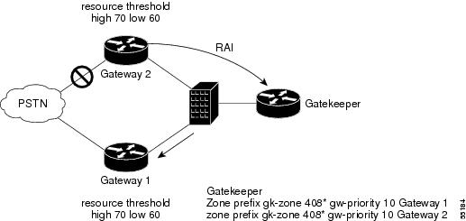
In this illustration, both gateways are configured to send RAIs to the gatekeeper and both have equal priority to handle calls destined to area code 408. In normal mode, calls are load balanced by turns between the two gateways. When Gateway 2 loses its connection to the PSTN, its DSP resource drops below the configured threshold and it sends an RAI to the gatekeeper, which then forwards all outbound area code 408 calls to Gateway 1.
Gatekeeper Redundancy
Cisco gatekeepers can be configured to use Hot Standby Routing Protocol (HSRP) so that a standby gatekeeper assumes the role if an active gatekeeper fails. A virtual HSRP IP address is configured on all gatekeepers in the HSRP group and is the common IP address to which the active gatekeeper responds. HSRP uses a priority scheme to identify one gatekeeper as active within a group. All remaining gatekeepers in the group are on standby. When the active gatekeeper fails to send a "hello" message within a configurable interval of time, the next gatekeeper in the group with the highest priority becomes the active gatekeeper and starts responding to the virtual HSRP IP address.
There is no load balancing among the multiple gatekeepers. Two or more gatekeepers can be grouped as an HSRP group, with the one having the highest priority being the active gatekeeper at any given time. The RAS address for all gatekeepers in the group will be the HSRP virtual address. Endpoints and gateways use this HSRP virtual address as their gatekeeper address. Using the HSRP virtual address as the gatekeeper address works even if the gateways attempt to discover the gatekeeper by using multicasting because only the active gatekeeper responds. All other gatekeepers are in standby mode and do not respond to a multicast or unicast request.
When a standby gatekeeper takes over because of the failure of an active gatekeeper, it does not have the state or the registrations of the failed gatekeeper. When a gateway or an endpoint attempts to initiate a new call by sending an ARQ, it will get an Admissions Reject (ARJ), indicating that the endpoint is not recognized. The gateways and uOne servers will need to reregister with the new gatekeeper before being able to make any calls.
Figure 32 shows an example of gatekeepers grouped together in an HSRP group to provide redundancy.
Figure 32 Redundant Gatekeepers Using HSRP
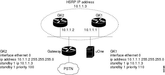
In Figure 32, GK1 has higher priority than GK2, and will become active and respond to the virtual HSRP IP address 10.1.1.3. The gateway and uOne server are configured to use 10.1.1.3 as the IP address of the gatekeeper. If GK1 fails, GK2 starts responding to the virtual IP address but does not yet have the gateway or the uOne server registered as H.323 gateways. When the gateway and the uOne server make the next attempt to register with the gatekeeper by sending a Registration Request (RRQ), they will get a Registration Confirm (RCF) response from GK2.
A Fully Redundant Configuration
A fully redundant POP site has multiple gateways, gatekeepers, fax gateways, and uOne servers. By implementing replication, the LDAP directory server can be made redundant at the core. A fully redundant configuration is shown in Figure 33.
Figure 33 Fully Redundant Configuration
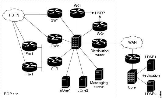
GW1 and GW2 are redundant gateways configured to send RAIs to the gatekeeper based on their available resources and the state of their connection to the PSTN. When a gateway loses its connection to the PSTN, it will send an RAI to the gatekeeper and force all outgoing calls to the other gateway.
GK1 and GK2 are two redundant gatekeepers configured for HSRP. They constantly monitor each other for availability, and take over its functions when the other gatekeeper is not available. The two uOne servers register with the gatekeeper with equal priority (the default is 5) and, in normal operation, handle incoming calls on a round robin basis. However, if one of the servers becomes unavailable, it loses its active registration with the gatekeeper, forcing all new calls to be handled by the remaining uOne server. The IOS SLB feature can be used for load balancing and redundancy on outbound faxes (off-ramp fax gateways).
Unified Messaging Configuration Examples
The section includes the following configuration examples:
•
•
Interoperability with Cisco and NetSpeak Gatekeepers
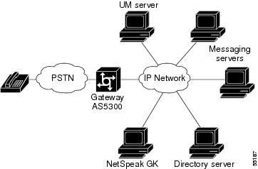
In this configuration example, the Cisco AS5300 gateway and uOne gateserver 4.1S are configured to use a NetSpeak gatekeeper to route calls. Direct inward dial can be used at the AS5300 to accommodate single stage dialing. Figure 34 illustrates the details of the network topology.
Figure 34 Interoperability with NetSpeak Gatekeeper
NetSpeak Gatekeeper Configuration Example
The following example shows how to configure the NetSpeak gatekeeper in Figure 34:
From the NetSpeak control centerSelect the route server (RS)Route configurationGatekeeper Zones (You will see your NetSpeak Gatekeeper defined here and Online)Associated gatewaysAdd GatewayPrimary alias (This is the H323-ID field defined in the AS5300)Alias type (H323)Vendor (Other)Country Code (1)Area Code (XXX)National Prefix (1)International Prefix (011)Time To Live - TTL (60)Number of ports (20)Associated Hunt Groups (From the Gateways Menu after you have added a gateway)Group Name (Name of a hunt group you want associated with your gateway)Beginning port number (0)Ending port number (19)Associated Codec CompatibilityStandard G.723.1 AudioStandard GSM audioStandard PCMCA audioStandard PCMU audioAssociated Route SetsRoute Set managementAdd a route setAssociated routesAdd E.164Country Code (1)Area Code (XXX)Beginning subscriber number (9933301)Ending Subscriber number (9933347)Number to dial (SN) - Subscriber NumberAdd the newly created route set with associated routes to the newly created hunt group.You need to repeat this same process for the other gateway. When you go to "Associated Gateways," you should see both gateways on line—this is an indication that they have registered with the gatekeeper. If you do not associate codecs with a gateway, the gateway will fail registration with the NetSpeak gatekeeper.
Cisco AS5300 Gateway Configuration Example
The following example shows how to configure the Cisco AS5300 gateway in Figure 34:
router# show running-config!version 12.0service timestamps debug uptimeservice timestamps log uptimeno service password-encryption!hostname tokyo-5300!enable password xxxx!resource-pool disable!ip subnet-zerono ip domain-lookupisdn switch-type primary-dms100cns event-service servermta receive maximum-recipients 1024!controller T1 0framing esfclock source line primarylinecode b8zspri-group timeslots 1-24!controller T1 1framing esfclock source line secondary 1linecode b8zspri-group timeslots 1-24!controller T1 2framing esflinecode b8zspri-group timeslots 1-24!controller T1 3framing esflinecode b8zspri-group timeslots 1-24!voice-port 0:Dvoice-port 1:Dvoice-port 2:Dvoice-port 3:D!dial-peer voice 1 voipdestination-pattern 9933...dtmf-relay cisco-rtpcodec g711ulawsession target ras!dial-peer voice 2 potsincoming called-number 9933...direct-inward-dial!process-max-time 200gateway!interface Ethernet0ip address 172.26.106.4 255.255.255.0no ip directed-broadcasth323-gateway voip interfaceh323-gateway voip id GK@hope.cisco.com ipaddr 172.26.106.10 1719h323-gateway voip h323-id tokyo-5300h323-gateway voip tech-prefix 8!interface Serial0:23no ip addressno ip directed-broadcastisdn switch-type primary-dms100isdn tei-negotiation first-callisdn incoming-voice modemfair-queue 64 256 50no cdp enable!interface Serial1:23no ip addressno ip directed-broadcastisdn switch-type primary-dms100isdn tei-negotiation first-callisdn incoming-voice modemfair-queue 64 256 0no cdp enable!interface Serial2:23no ip addressno ip directed-broadcastisdn switch-type primary-dms100isdn tei-negotiation first-callfair-queue 64 256 0no cdp enable!interface Serial3:23no ip addressno ip directed-broadcastisdn switch-type primary-5essfair-queue 64 256 0no cdp enable!interface FastEthernet0no ip addressno ip directed-broadcastshutdownduplex autospeed auto!ip classlessip route 0.0.0.0 0.0.0.0 172.26.106.1no ip http server!line con 0transport input noneline aux 0line vty 0 4password xxxxlogin!endCisco Gateway and Gatekeeper Configuration for Two-Stage Dialing
In the following configuration examples, the UM server registers with the gatekeeper with a technology prefix of 4#, which also happens to be the default technology prefix defined in the gatekeeper. The gateway also must be registered with the gatekeeper, because all calls to the UM server must be routed via the gatekeeper. This particular example illustrates a two-stage dialing model, where subscribers dial a phone number to access the gateway and then use a token (265) to access the unified messaging services.
The following configuration shows how to configure the gateway described in the scenario above:
Gateway# show running-config!version 12.0service timestamps debug uptimeservice timestamps log uptimeno service password-encryption!hostname Gateway!enable password xxxx!resource-pool disable!ip subnet-zerono ip domain-lookupip host hope.cisco.com 172.26.106.6ip host faith.cisco.com 172.26.106.3ip host charity.cisco.com 172.26.106.2!isdn switch-type primary-dms100cns event-service servermta receive maximum-recipients 1024!controller T1 0framing esfclock source line primarylinecode b8zspri-group timeslots 1-24!controller T1 1framing esfclock source line secondary 1linecode b8zspri-group timeslots 1-24!controller T1 2framing esflinecode b8zspri-group timeslots 1-24!controller T1 3framing esflinecode b8zspri-group timeslots 1-24!voice-port 0:Dvoice-port 1:Dvoice-port 2:Dvoice-port 3:D!dial-peer voice 1 voipdestination-pattern 265dtmf-relay cisco-rtpcodec g711ulawsession target ras!process-max-time 200gateway!interface Ethernet0ip address 172.26.106.4 255.255.255.0no ip directed-broadcasth323-gateway voip interfaceh323-gateway voip id gk-splob ipaddr 172.26.106.8 1719h323-gateway voip h323-id tokyo-5300h323-gateway voip tech-prefix 8!interface Serial0:23no ip addressno ip directed-broadcastisdn switch-type primary-dms100isdn tei-negotiation first-callisdn incoming-voice modemfair-queue 64 256 50no cdp enable!interface Serial1:23no ip addressno ip directed-broadcastisdn switch-type primary-dms100isdn tei-negotiation first-callisdn incoming-voice modemfair-queue 64 256 0no cdp enable!interface Serial2:23no ip addressno ip directed-broadcastisdn switch-type primary-dms100isdn tei-negotiation first-callfair-queue 64 256 0no cdp enable!interface Serial3:23no ip addressno ip directed-broadcastisdn switch-type primary-5essfair-queue 64 256 0no cdp enable!interface FastEthernet0no ip addressno ip directed-broadcastshutdownduplex autospeed auto!ip classlessip route 0.0.0.0 0.0.0.0 172.26.106.1no ip http server!line con 0transport input noneline aux 0line vty 0 4password xxxxlogin!endThe following show command output displays the status of this gateway:
Gateway# show gatewayGateway tokyo-5300 is registered to Gatekeeper gk-splobAlias list (CLI configured)H323-ID tokyo-5300Alias list (last RCF)H323-ID tokyo-5300H323 resource thresholding is DisabledThe following configuration shows how to configure the gatekeeper described in the scenario:
Gatekeeper# show running-config!version 12.0service timestamps debug uptimeservice timestamps log uptimeno service password-encryption!hostname Gatekeeper!boot system flash c2600-ix-mz.120-5.T1boot system flash c2600-js-mz.120-5.XK1enable password xxxx!ip subnet-zerono ip domain-lookup!ip dvmrp route-limit 20000!process-max-time 200!interface Ethernet0/0ip address 172.26.106.8 255.255.255.0no ip directed-broadcast!interface Ethernet0/1no ip addressno ip directed-broadcastshutdown!ip classlessip route 0.0.0.0 0.0.0.0 172.26.106.1no ip http server!gatekeeperzone local gk-splob cisco.comgw-type-prefix 4#* default-technologyno use-proxy gk-splob default inbound-to terminalno shutdown!line con 0transport input noneline aux 0line vty 0 4password xxxxloginThe following show gateway command output displays the gateway technology prefix table for this gatekeeper:
Gatekeeper# show gateway gw-type-prefixGATEWAY TYPE PREFIX TABLE=========================Prefix: 4#* (Default gateway-technology)Zone gk-splob master gateway list:172.26.106.2:1720 Charity-UMPrefix: 8*Zone gk-splob master gateway list:172.26.106.4:1720 tokyo-5300The following show gateway command output displays the status of all registered endpoints for this gatekeeper:
Gatekeeper# show gatekeeper endpointsTotal number of active registrations = 2GATEKEEPER ENDPOINT REGISTRATION================================CallSignalAddr Port RASSignalAddr Port Zone Name Type F--------------- ----- --------------- ----- --------- ---- --172.26.106.2 1720 172.26.106.2 32795 gk-splob VOIP-GWH323-ID: Charity-UM172.26.106.4 1720 172.26.106.4 1803 gk-splob VOIP-GWH323-ID: tokyo-5300Related Documents
•
•
 Feedback
Contact Cisco
- Open a Support Case

- (Requires a Cisco Service Contract)
This Document Applies to These Products
- Collaboration Endpoints - Retired Products
- Conferencing - Retired Products
- Contact Center - Retired Products
- Optical Networking - Retired Products
- Routers - Retired Products
- Security - Retired Products
- Servers - Unified Computing (UCS) Retired Products
- Storage Networking Retired Products
- Switches - Retired Products
- Video - Retired Products
- Wireless - Retired Products