Transporting 802.1q Tags over ATM
Available Languages
Table Of Contents
Transporting 802.1q Tags over ATM PVCs for ADSL
Prerequisites for Transporting 802.1q Tags over ATM PVCs for ADSL
Restrictions for Transporting 802.1q Tags over ATM PVCs for ADSL
Information About Transporting 802.1q Tags over ATM PVCs for ADSL
VLAN-Based Service Differentiation over ADSL
How to Transport 802.1q Tags over ATM PVCs for xDSL
Troubleshooting the Transport of 802.1q Tags over ATM PVCs for ADSL
Configuration Examples for Transporting 802.1q Tags over ATM PVCs for ADSL
Transporting 802.1q Tags over ATM PVCs for ADSL
Revised: Month Day, Year, OL-20180-01First Published: Month Day, YearLast Updated: September 24, 2009This feature allows 802.1q tags to be transported over Asynchronous Transfer Mode (ATM) permanent virtual circuits (PVC) used in ADSL2+ uplinks. This feature offers the following benefits:
•
It allows Customer Premise Equipment (CPE) to carry traffic with provider-specific 802.1q-tag.
•

Note
Finding Feature Information
Your software release may not support all the features documented in this module. For the latest feature information and caveats, see the release notes for your platform and software release.
Use Cisco Feature Navigator to find information about platform support and Cisco IOS and Catalyst OS software image support. To access Cisco Feature Navigator, go to http://www.cisco.com/go/cfn. An account on Cisco.com is not required.
Contents
•
•
•
•
•
Prerequisites for Transporting 802.1q Tags over ATM PVCs for ADSL
Configuration Skills
•
Routers Supported
The following table lists the routers supported in this release.
Restrictions for Transporting 802.1q Tags over ATM PVCs for ADSL
The following restrictions apply to this release:
•
•
•
•
Information About Transporting 802.1q Tags over ATM PVCs for ADSL
This feature supports the deployment of voice, video, and data services on customer premises equipment (CPE) by enabling the router to transport 802.1q tags over Asynchronous Transfer Mode (ATM) permanent virtual circuits (PVC). This feature requires an ADSL2+ data connection.
This section contains the following subsections:
•
VLAN-Based Service Differentiation over ADSL
VLAN-Based service differentiation allows service providers to offer a range of broadband-enabled services and applications to end users. It supports IP connectivity applications that require real-time network performance and applications that use best-effort, or Internet-grade performance.
This feature allows the local VLAN configuration and class-of-traffic configuration to be preserved. An administrator need not change the original 802.1p class-of-traffic tags or 802.1q VLAN tags. The original VLAN tag in an inbound packet is changed to the value configured by the Cisco IOS bridge-dot1q encap command before it leaves the router. For example, if the command bridge-dot1q encap 10 command were entered, a VLAN tag of 70 in a packet inbound from the local network would be changed to a value of 10 in the egress packet. Any 802.1p value is changed to 0, and non VLAN-tagged frames are discarded.
From an Ethernet perspective, this service is carried over a dedicated VLAN from the handover point to the end user premises. This is shown in Figure 1.
Figure 1 VLAN-Based Service Differentiation at PVC Level
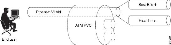
The Ethernet VLAN used by the voice, video, and data services must be identified at the customer premises by an 802.1q VLAN ID configured using the bridge-dot1q encap Cisco IOS CLI command. The VLAN is identified at the service provider's end by a service-provider-assigned 802.1ad customer VLAN ID.
The bridge-dot1q encap Cisco IOS CLI command changes the local VLAN ID to the VLAN ID required by the service provider to implement VLAN-based service differentiation.The operation of this command is shown in Figure 2.
Figure 2 Operation of bridge-dot1q encap command
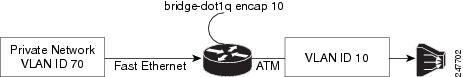
Figure 3 and Figure 4 show the PDU data structure in greater detail.
Transporting 802.1q Tags
A new Cisco IOS command inserts the 802.1q VLAN tag into the MAC PDU, and this PDU is sent to the DSLAM. Incoming and outgoing PDU structures are shown in Figure 3 and in Figure 4.
Figure 3 shows the packet structure when the incoming Ethernet frames do not have a VLAN header.
Figure 3 Incoming and Outgoing Packet Structures When No Incoming VLAN ID is Present
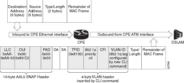
The diagram of the outgoing packet shows that a 4-byte VLAN header has been inserted, with an 802.1p value of 0 (best effort). The VLAN ID value is configured by the command described in this document.
Figure 4 shows the incoming packet structure when the incoming Ethernet packets contain a VLAN header.
Figure 4 Incoming and Outgoing Packet Structures When an Incoming VLAN ID is Present
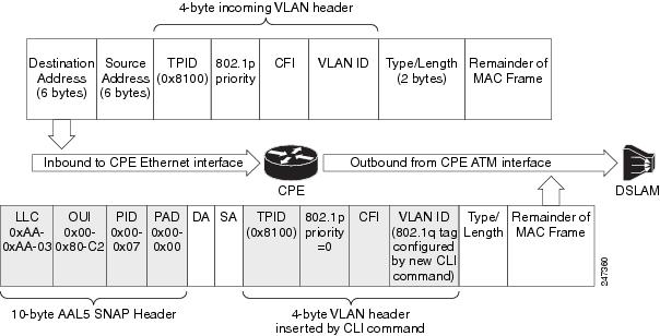
The outgoing packet structure is the same as in Figure 3, but note that whatever 802.1p priority may have been configured is changed to 0, and any VLAN ID configured is set to the ID configured by the command described in this document.
How to Transport 802.1q Tags over ATM PVCs for xDSL
This section contains the following subsections:
•
Restrictions
•
SUMMARY STEPS
1.
2.
3.
4.
5.
6.
7.
8.
DETAILED STEPS
Troubleshooting the Transport of 802.1q Tags over ATM PVCs for ADSL
If the 802.1q tags are not being transported in the MAC PDUs sent to the DSLAM, verify that the following configuration commands are in place:
•
•
Configuration Examples for Transporting 802.1q Tags over ATM PVCs for ADSL
Three use case examples are provided in this section:
Example for Use Case 1
In this use case, traffic from multiple incoming VLANs is bridged to a single outgoing VLAN. The traffic is arriving on Layer-2 Fast Ethernet ports, and a DHCP server assigns IP addresses on the private network. Network Address Translation (NAT) is enabled. A static IP address is used on the outgoing BVI interface.
This topology is shown in Figure 5.
Figure 5 Use Case 1 Topology
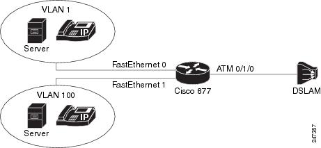
The following configuration is for the Cisco 877 router.
ip dhcp excluded-address 192.168.10.1ip dhcp excluded-address 192.168.20.1!ip dhcp pool test_pool1network 192.168.10.0 255.255.255.0default-router 192.168.10.1!ip dhcp pool test_pool2network 192.168.20.0 255.255.255.0default-router 192.168.20.1!!bridge irb!!interface ATM0no ip addressno atm ilmi-keepalive!interface ATM0.1 point-to-pointbridge-group 1bridge-group 1 spanning-disabledpvc 0/110bridge-dot1q encap 10encapsulation aal5snap!interface FastEthernet0switchport access vlan 1!interface FastEthernet1switchport access vlan 100!interface Vlan1ip address 192.168.10.1 255.255.255.0ip nat insideip virtual-reassembly!interface Vlan100ip address 192.168.20.1 255.255.255.0ip nat insideip virtual-reassembly!interface BVI1ip address 12.0.0.1 255.0.0.0ip nat outsideip virtual-reassembly!ip forward-protocol ndip route 0.0.0.0 0.0.0.0 12.0.0.2ip nat pool test 12.0.0.1 12.0.0.1 netmask 255.0.0.0ip nat inside source list 101 pool test overloadip nat inside source list 102 pool test overload!access-list 101 permit ip 192.168.10.0 0.0.0.255 any logaccess-list 102 permit ip 192.168.20.0 0.0.0.255 any log!bridge 1 protocol ieeebridge 1 route ip!Example for Use Case 2
In this use case traffic from multiple VLANs arrive at the router over a Layer-3 port. All this traffic is bridged over a single ATM virtual circuit to the service provider's DSLAM and tagged with a single VLAN tag. Both WAN and LAN IP addresses are provided by DHCP servers.
This topology is shown in Figure 6.
Figure 6 Use Case 2 Topology
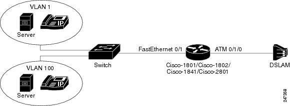
The following configuration is for the Cisco 877 router.
ip dhcp excluded-address 192.168.10.1ip dhcp excluded-address 192.168.20.1!ip dhcp pool test_pool1network 192.168.10.0 255.255.255.0default-router 192.168.10.1!ip dhcp pool test_pool2network 192.168.20.0 255.255.255.0default-router 192.168.20.1!bridge irb!!interface FastEthernet0/1no ip addressduplex autospeed auto!interface FastEthernet0/1.1encapsulation dot1Q 100ip address 192.168.10.1 255.255.255.0ip nat insideip virtual-reassembly!interface FastEthernet0/1.2encapsulation dot1Q 1 nativeip address 192.168.20.1 255.255.255.0ip nat insideip virtual-reassembly!interface ATM0/1/0no ip addressno atm ilmi-keepalive!!interface ATM0/1/0.1 point-to-pointbridge-group 1bridge-group 1 spanning-disabledpvc 9/117bridge-dot1q encap 10encapsulation aal5snap!!interface BVI1ip address dhcpip nat outsideip virtual-reassembly!ip forward-protocol nd!ip nat inside source list 101 interface BVI1 overloadip nat inside source list 102 interface BVI1 overload!access-list 101 permit ip 192.168.10.0 0.0.0.255 any logaccess-list 102 permit ip 192.168.20.0 0.0.0.255 any log!bridge 1 protocol ieeebridge 1 route ipAdditional References
The following sections provide references related to the Transporting 802.1q Tags over ATM PVCs for ADSL feature.
Related Documents
Standards
MIBs
None
To locate and download MIBs for selected platforms, Cisco IOS releases, and feature sets, use Cisco MIB Locator found at the following URL:
RFCs
Technical Assistance
Command Reference
This section documents one new command only.
•
bridge-dot1q
To transport a VLAN ID over an ATM ADSL link, use the bridge-dot1q command in PVC configuration mode. To prevent a VLAN ID from being sent across the link, use the no form of this command.
bridge-dot1q encap outbound-vlan-id
no bridge-dot1q encap outbound-vlan-id
Syntax Description
outbound-vlan-id
The VLAN ID to be carried over an ATM ADSL link. The valid value of the VLAN ID can range from 1 to 4094.
Command Default
The command is enabled in point-to-point subinterface.
Command Modes
ATM PVC configuration mode (config-if-atm-vc).
Command History
Usage Guidelines
See Restrictions for Transporting 802.1q Tags over ATM PVCs for ADSL, and Restrictions.
Glossary
802.1ad—An amendment to IEEE 802.1q that enables a service provider to offer bridged VLANs over its network.
802.1p—A 3 bit field within an Ethernet frame header when using IEEE 802.1Q on an IEEE 802.1D network. It specifies a priority value of between 0 and 7 inclusive that can be used by Quality of Service (QoS) disciplines to differentiate traffic.
802.1q—A networking standard written by the IEEE 802.1 workgroup allowing multiple bridged networks to transparently share the same physical network link without leakage of information between networks. 802.1q is commonly referred to as VLAN tagging.
AAL5SNAP—ATM Adaptation Layer 5 Subnetwork Protocol Access Protocol. A type of network encapsulation that supports multiplexing of 2 or more protocols over a virtual circuit.
ATM—Asynchronous Transfer Mode. The international standard for cell relay in which multiple service types (such as voice, video, or data) are conveyed in fixed-length (53-byte) cells. Fixed-length cells allow cell processing to occur in hardware, thereby reducing transit delays. ATM is designed to take advantage of high-speed transmission media, such as E3, SONET, and T3.
BVI—Bridge Group Virtual Interface. Logical Layer 3-only interface associated with a bridge group when IRB is configured.
CPE—customer premises equipment. Terminating equipment, such as terminals, telephones, and modems, supplied by the telephone company, installed at customer sites, and connected to the telephone company network. Can also refer to any telephone equipment residing on the customer site.
CVLAN—Customer Virtual Local Area Network.
DSL—digital subscriber line. Public network technology that delivers high bandwidth over conventional copper wiring at limited distances. There are four types of DSL: ADSL, HDSL, SDSL, and VDSL.
DSLAM—digital subscriber line access multiplexer. A device that connects many digital subscriber lines to a network by multiplexing the DSL traffic onto one or more network trunk lines.
IRB—integrated routing and bridging. Integrated Services Digital Network (ISDN) User Part. An upper-layer application supported by Signalling System 7 for connection set up and tear down.
NAT—Network Address Translation. Mechanism for reducing the need for globally unique IP addresses. NAT allows an organization with addresses that are not globally unique to connect to the Internet by translating those addresses into globally routable address space. Also known as Network Address Translator.
PVC—permanent virtual circuit (or connection). A virtual circuit that is permanently established. PVCs save bandwidth associated with circuit establishment and tear down in situations where certain virtual circuits must exist all the time. In ATM terminology, called a permanent virtual connection.
VoIP—Voice over IP. The capability to carry normal telephony-style voice over an IP-based internet with POTS-like functionality, reliability, and voice quality.
CCDE, CCENT, CCSI, Cisco Eos, Cisco HealthPresence, Cisco Ironport, the Cisco logo, Cisco Lumin, Cisco Nexus, Cisco Nurse Connect, Cisco Stackpower, Cisco StadiumVision, Cisco TelePresence, Cisco Unified Computing System, Cisco WebEx, DCE, Flip Channels, Flip for Good, Flip Mino, Flip Video, Flip Video (Design), Flipshare (Design), Flip Ultra, and Welcome to the Human Network are trademarks; Changing the Way We Work, Live, Play, and Learn, Cisco Store, and Flip Gift Card are service marks; and Access Registrar, Aironet, AsyncOS, Bringing the Meeting To You, Catalyst, CCDA, CCDP, CCIE, CCIP, CCNA, CCNP, CCSP, CCVP, Cisco, the Cisco Certified Internetwork Expert logo, Cisco IOS, Cisco Press, Cisco Systems, Cisco Systems Capital, the Cisco Systems logo, Cisco Unity, Collaboration Without Limitation, EtherFast, EtherSwitch, Event Center, Fast Step, Follow Me Browsing, FormShare, GigaDrive, HomeLink, Internet Quotient, IOS, iPhone, iQuick Study, IronPort, the IronPort logo, LightStream, Linksys, MediaTone, MeetingPlace, MeetingPlace Chime Sound, MGX, Networkers, Networking Academy, Network Registrar, PCNow, PIX, PowerPanels, ProConnect, ScriptShare, SenderBase, SMARTnet, Spectrum Expert, StackWise, The Fastest Way to Increase Your Internet Quotient, TransPath, WebEx, and the WebEx logo are registered trademarks of Cisco Systems, Inc. and/or its affiliates in the United States and certain other countries.
All other trademarks mentioned in this document or website are the property of their respective owners. The use of the word partner does not imply a partnership relationship between Cisco and any other company. (0907R)
Any Internet Protocol (IP) addresses and phone numbers used in this document are not intended to be actual addresses and phone numbers. Any examples, command display output, network topology diagrams, and other figures included in the document are shown for illustrative purposes only. Any use of actual IP addresses or phone numbers in illustrative content is unintentional and coincidental.
© 2009 Cisco Systems, Inc. All rights reserved.
 Feedback
Contact Cisco
- Open a Support Case

- (Requires a Cisco Service Contract)
This Document Applies to These Products
- Collaboration Endpoints - Retired Products
- Conferencing - Retired Products
- Contact Center - Retired Products
- Optical Networking - Retired Products
- Routers - Retired Products
- Security - Retired Products
- Servers - Unified Computing (UCS) Retired Products
- Storage Networking Retired Products
- Switches - Retired Products
- Video - Retired Products
- Wireless - Retired Products