R2 and ISUP Transparency for Voice Gateways Version 2.0
Available Languages
Table Of Contents
R2 and ISUP Transparency for Voice Gateways Version 2.0
Non-standard CPC Support Using FDC and PRN
Supported Standards, MIBs, and RFCs
Configuring ISUP Forwarding in H.225 Messages Globally
Configuring ISUP Forwarding in H.225 Messages for a Dial Peer
Verifying ISUP Forwarding in H.225 Messages
R2 Transparency Configuration Example
CLIP and CLIR Configuration Example
R2 and ISUP Transparency for Voice Gateways Version 2.0

Note
This document is still under development. Please revisit this site for future updates. 11/18/07
Feature History
12.2(11)T
This feature was introduced on the Cisco 3600, Cisco AS5300, Cisco AS5350, Cisco AS5400, Cisco AS5800, Cisco AS5850, and Cisco 7200 series.
This document describes enhancements to ISDN User Part (ISUP) transparency, R2-to-ISUP interworking, and R2 transparency using Generic Transparency Descriptor (GTD) objects in Cisco IOS Release 12.2(11)T. This document includes the following sections:
•
Feature Overview
This feature provides ISUP transparency, R2-to-ISUP interworking, and R2 transparency using GTD objects.Cisco IOS Release 12.2(11)T also provides support for Calling Line ID Presentation (CLIP) and Calling Line ID Restriction (CLIR) interworking between ISUP and H.225. This feature is part of the
Cisco SS7 Interconnect for Voice Gateways Solution Documentation.GTD objects are generically used to represent ISUP messages, parameters, and R2 signals. These GTD objects are encapsulated into existing signaling protocols (for example, H.225), facilitating end-to-end transport. Existing implementations of ISUP transparency and R2 transparency use ISUP binary format, rather than GTD ASCII format, to transport ISUP and R2 signaling parameters. Using GTD as a transport mechanism for signaling data in Cisco IOS software provides a common format for sharing signaling data among various components in a network and for interworking various signaling protocols.
This feature adds the following additional functionality:
•
•
•
ISUP Transparency Using GTD
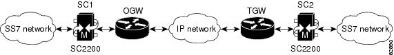
An ISDN message that comes into the Cisco originating gateway (OGW) from a Cisco PGW 2200 signaling controller on the NI2+ interface contains the ISUP GTD message, as shown in Figure 1.
The following is an example of the ISUP GTD call flow:
1.
2.
3.
4.
Note
Figure 1 ISUP Transparency Implementation
R2 Transparency Using GTD
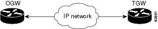
Channel-associated signaling (CAS) R2 signals that come into the OGW are passed transparently across the network, as shown in Figure 2.
The following is an example of the R2 GTD call flow:
1.
2.
Figure 2 R2 Transparency Implementation
Non-standard CPC Support Using FDC and PRN
In normal circumstances, Universal Feature Card (UFC) Generic Transparency Descriptor (GTD) parameters are used to pass the country code and the signal value end-to-end. UFC is used to provide R2-R2 transparency when the same version (or variant) of R2 signaling is being used at both ends. CPC and PRN parameters are used for R2-ISUP interworking and for unlike R2 versions (or variants) of R2-R2 interworking. The CPC GTD parameter carries the CPC value, and the Problem Report Number (PRN) parameter carries the country code. But for countries like Thailand, a direct mapping of the group II signals to GTD CPC cannot be achieved, because the Thai R2 variant has CPC values that do not map into the GTD defined list of CPC values.
To solve this problem of transporting nonstandard CPC values for certain countries, a new GTD parameter called Field Compatibility Information (FDC) is used. An FDC field is used to allow customer-specific values of known fields to be transmitted, even though the actual field is populated with a best-fit mapping. The FDC carries the actual parameter value received at the R2 interface, and the CPC carries the best-fit GTD-known value.
The algorithm at the terminating gateway has been modified to look for a CPC value in the following order:
1.
a.
b.
2.
The following example shows mapping information for Thailand, because only Thailand requires FDC data at this time. This data is used to map the R2 CPC to the GTD FDC.
const uchar r2_grpII_to_gtd_fdc[CAS_R2_NUM_SIGNALS] =/* 1 2 3 4 5 6 7 8 9 10 11 12 13 14 15 */{ 0, 0, 0, 0, 0, 0, 0xf9, 0, 0, 0xfb, 0, 0, 0, 0, 0}; /*Thailand*/Benefits
ISUP Transparency Using GTD and R2 Transparency Using GTD
This feature allows optional parameters to be passed transparently through the Cisco SS7 Interconnect for Voice Gateways solution.
R2-to-ISUP Interworking Using GTD
This feature allows different values of CATEGORY and ANSWER signal group B parameters to be passed transparently from the ingress side to the egress side of the Cisco SS7 Interconnect for Voice Gateways solution.
CLIP and CLIR Supplementary Services
This feature allows full mapping of the calling number, screening indicator, and presentation indicator from ISUP to NI2+ to H.323 and supports the following additional services:
•
•
•
•
No Change to Existing Interfaces
This feature does not change existing interfaces between modules. It makes use of the cas_relay_signal structure to interface between the R2 register-signaling module and the TSP layer.
Restrictions
To use the ISUP transparency and R2-to-ISUP interworking features on the gateway, one or more properly configured Cisco PGW 2200 signaling controllers are required in the network.
Related Documents
Cisco IOS Documentation
•
•
Cisco Gatekeeper Transaction Message Protocol Documentation
•
Cisco SS7 Interconnect for Voice Gateways Solution Documentation
•
•
•
Cisco Media Gateway Controller Documentation
•
•
•
•
Supported Platforms
•
•
•
•
•
•
•
Determining Platform Support Through Cisco Feature Navigator
Cisco IOS software is packaged in feature sets that are supported on specific platforms. To get updated information regarding platform support for this feature, access Cisco Feature Navigator. Cisco Feature Navigator dynamically updates the list of supported platforms as new platform support is added for the feature.
Cisco Feature Navigator is a web-based tool that enables you to quickly determine which Cisco IOS software images support a specific set of features and which features are supported in a specific Cisco IOS image. You can search by feature or release. Under the release section, you can compare releases side by side to display both the features unique to each software release and the features in common.
To access Cisco Feature Navigator, you must have an account on Cisco.com. If you have forgotten or lost your account information, send a blank e-mail to cco-locksmith@cisco.com. An automatic check will verify that your e-mail address is registered with Cisco.com. If the check is successful, account details with a new random password will be e-mailed to you. Qualified users can establish an account on Cisco.com by following the directions found at this URL:
Cisco Feature Navigator is updated regularly when major Cisco IOS software releases and technology releases occur. For the most current information, go to the Cisco Feature Navigator home page at the following URL:
Availability of Cisco IOS Software Images
Platform support for particular Cisco IOS software releases is dependent on the availability of the software images for those platforms. Software images for some platforms may be deferred, delayed, or changed without prior notice. For updated information about platform support and availability of software images for each Cisco IOS software release, refer to the online release notes or, if supported, Cisco Feature Navigator.
Supported Standards, MIBs, and RFCs
Standards
•
•
•
MIBs
No new or modified MIBs are supported by this feature.
To locate and download MIBs for selected platforms, Cisco IOS releases, and feature sets, use Cisco MIB Locator found at the following URL:
http://tools.cisco.com/ITDIT/MIBS/servlet/index
If Cisco MIB Locator does not support the MIB information that you need, you can also obtain a list of supported MIBs and download MIBs from the Cisco MIBs page at the following URL:
http://www.cisco.com/public/sw-center/netmgmt/cmtk/mibs.shtml
To access Cisco MIB Locator, you must have an account on Cisco.com. If you have forgotten or lost your account information, send a blank e-mail to cco-locksmith@cisco.com. An automatic check will verify that your e-mail address is registered with Cisco.com. If the check is successful, account details with a new random password will be e-mailed to you. Qualified users can establish an account on Cisco.com by following the directions found at this URL:
RFCs
No new or modified RFCs are supported by this feature.
Prerequisites
You must configure your Voice over IP (VoIP) network and the Cisco SS7 Interconnect for Voice Gateways solution, including the following components:
•
•
•
•
For more information on configuring these components, see the documents in the "Related Documents" section.
You must have the following software installed on your solution components:
•
•
•
Note
http://www.cisco.com/univercd/cc/td/doc/product/access/sc/rel7/soln/voip13/voip_rn.htm
Configuration Tasks
See the following sections for configuration tasks for this feature. Each task in the list is identified as either required or optional.
•
•
•
•
•
•
•
Configuring R2 Transparency
To enable R2 transparency using GTD on the router, use the following commands beginning in global configuration mode:
Verifying R2 Transparency
To verify the R2 transparency configuration, perform the following steps:
Step 1
Step 2
Configuring ISUP Forwarding in H.225 Messages Globally
To forward the ISUP GTD payload to the far-end signaled endpoint for all dial peers on the gateway, use the following commands beginning in global configuration mode:
Configuring ISUP Forwarding in H.225 Messages for a Dial Peer
To forward the ISUP GTD payload to the far-end signaled endpoint for a specific dial peer, use the following commands beginning in global configuration mode:
Verifying ISUP Forwarding in H.225 Messages
To verify the ISUP forwarding configuration, perform the following steps:
Step 1
Step 2
Configuring CLIP and CLIR
To configure CLIP and CLIR, use the following commands beginning in global configuration mode:
Note
Verifying CLIP and CLIR
To verify the CLIP and CLIR configuration, perform the following steps:
Step 1
Step 2
Configuration Examples
This section provides the following configuration examples:
•
•
R2 Transparency Configuration Example
The following is a sample configuration for R2 transparency. Commands that appear in the configuration task tables for R2 transparency but that do not appear in the running configuration output are configured for their default settings.
Router# show running-config!!!controller E1 4/0pri-group timeslots 1-31 nfas_d primary nfas_int 0 nfas_group 0!controller E1 4/1pri-group timeslots 1-31 nfas_d none nfas_int 1 nfas_group 0!controller E1 4/2pri-group timeslots 1-31 nfas_d none nfas_int 2 nfas_group 0!controller E1 4/3pri-group timeslots 1-31 nfas_d primary nfas_int 0 nfas_group 1!controller E1 4/4ds0-group 0 timeslots 1-15,17-31 type r2-digital r2-compelledcas-custom 0country thailand use-defaultsmeteringcategory 2signal-end-to-endanswer-signal group-b 5!controller E1 4/5ds0-group 0 timeslots 1-15,17-31 type r2-digital r2-compelledcas-custom 0country thailand use-defaultsmeteringcategory 2signal-end-to-endanswer-signal group-b 5!controller E1 4/6pri-group timeslots 1-31!!!CLIP and CLIR Configuration Example
The following is a sample configuration for CLIP and CLIR. Commands that appear in the configuration task tables for CLIP and CLIR but that do not appear in the running configuration output are configured for their default settings.
Router# show running-config!!!dial-peer voice 123 potsdestination-pattern 6969clid network-number 101010101clid second-number stripno digit-stripdirect-inward-dialport 6/0:D!dial-peer voice 1234 voipincoming called-number 6969!!!Command Reference
This section documents new commands. All other commands used with this feature are documented in the Cisco IOS Release 12.2 command reference publications.
clid network-number
To configure a network number in the router for calling line ID (CLID) and to use it as the calling party number, use the clid network-number command in dial-peer configuration mode. To remove a configured network number from the router, use the no form of this command.
clid network-number number [second-number strip]
no clid network-number number [second-number strip]
Syntax Description
number
Calling party network number.
second-number strip
(Optional) Prevents the second network number from being sent in the CLID information.
Defaults
No default behavior or values.
Command Modes
Dial-peer configuration
Command History
Usage Guidelines
This command sets the presentation indicator to "y" and the screening indicator to "network-provided."
Examples
The following example sets the calling party network number to 98765 for POTS dial peer 4321:
Router(config)# dial-peer voice 4321 potsRouter(config-dial-peer)# clid network-number 98765The following example sets the calling party network number to 56789 for VoIP dial peer 1234, and also prevents the second network number from being sent:
Router(config)# dial-peer voice 1234 voipRouter(config-dial-peer)# clid network-number 56789 second-number stripRelated Commands
clid restrict
To prevent the calling party number from being presented by calling line ID (CLID), use the clid restrict command in dial-peer configuration mode. To remove the restriction, use the no form of this command.
clid restrict
no clid restrict
Syntax Description
This command has no arguments or keywords.
Defaults
No default behavior or values
Command Modes
Dial-peer configuration
Command History
Usage Guidelines
If this command is issued, the calling party number will still be in the information element, but the presentation indicator will be set to "n" to prevent the presentation.
Examples
The following example prevents the calling party number from being presented:
Router(config-dial-peer)# clid restrictRelated Commands
clid second-number strip
To prevent the second network number from being sent in the calling line ID (CLID) information, use the clid second-number strip command in dial-peer configuration mode. To allow the second network number to be sent, use the no form of this command.
clid second-number strip
no clid second-number strip
Syntax Description
This command has no arguments or keywords.
Defaults
No default behavior or values
Command Modes
Dial-peer configuration
Command History
Usage Guidelines
This command prevents the H.225 source address field from containing the original calling party number.
Note
Examples
The following example prevents the second network number from being sent in the CLID information:
Router(config-dial-peer)# clid second-number stripAn alternative method of accomplishing this is to enter the second-number strip keywords as part of the clid network-number command. The following example sets the calling party network number to 56789 for VoIP dial peer 1234, and also prevents the second network number from being sent:
Router(config)# dial-peer voice 1234 voipRouter(config-dial-peer)# clid network-number 56789 second-number stripRelated Commands
clid strip
To remove the calling party number information from the calling line ID (CLID) information and to prevent the calling party number from being presented, use the clid strip command in dial-peer configuration mode. To remove the restriction, use the no form of this command.
clid strip
no clid strip
Syntax Description
This command has no arguments or keywords.
Defaults
No default behavior or values.
Command Modes
Dial-peer configuration
Command History
Usage Guidelines
If this command is issued, the calling party number will be null in the information element, and the presentation indicator will be set to "n" to prevent the presentation.
Examples
The following example removes the calling party number information from the CLID information and prevents the calling party number from being presented:
Router(config-dial-peer)# clid stripRelated Commands
signaling forward
To choose if a Cisco IOS gateway forwards the Generic Transparency Descriptor (GTD) payload to another gateway, use the signaling forward command. To enable this feature system-wide, use the signaling forward command in voice service voip configuration mode. To enable this feature for an individual voip dial peer, use the signaling forward command in voice dial-peer configuration mode. To disable forwarding, use the no form of this command.
signaling forward {none | unconditional | conditional}
no signaling forward
Syntax Description
Defaults
none (Signaling forwarding is not enabled.)
Command Modes
Dial-peer configuration (individual dial peers)
Voice service voip configuration (system wide)Command History
Usage Guidelines
This command is used with the Cisco PGW 2200 signaling controller in the Cisco SS7 Interconnect for Voice Gateways solution. You must configure the Cisco PGW 2200 to encapsulate SS7 ISDN User Part messages in GTD format before using this command on the Cisco gateway.
This command does not prevent sending the GTD to a gatekeeper. Any GTD on the originating gateway will be sent to the gatekeeper for use in routing decisions. To prevent GTD creation, the signal-end-to-end command-line interface option on the R2 interfaces should be turned off, and the Cisco PGW 2200 should be configured not to send GTD to the gateway.
Examples
The following example shows unconditional signaling forwarding on a system-wide basis, where the GTD payload is tunneled in H.225 SETUP messages to endpoints:
Router(config)# voice service voipRouter(conf-voi-serv)# signaling forward unconditionalRouter(conf-voi-serv)# ^ZRouter# show running-configBuilding configuration...Current configuration : 4201 bytes!version 12.2service configno service single-slot-reload-enableno service padservice timestamps debug uptimeservice timestamps log uptimeno service password-encryptionservice internalservice udp-small-servers!hostname as5300-2!no logging bufferedlogging rate-limit console 10 except errorsaaa new-model!...!voice service voipsignaling forward unconditionalh323!...Glossary
BCI—backward call indicator.
CAS—channel-associated signaling.
CCS7—Common Channel Signaling No. 7. Another name for SS7.
CLID—Calling Line ID.
CLIP—Calling Line ID Presentation.
CLIR—Calling Line ID Restriction.
CPC—Nonstandard calling party category.
FDC—Known field compatibility.
GTD—Generic Transparency Descriptor.
H.225.0—An ITU standard that governs H.225.0 session establishment and packetization. H.225.0 actually describes several different protocols: RAS, Q.931, and RTP.
ISDN—Integrated Services Digital Network. Communication protocol offered by telephone companies that permits telephone networks to carry data, voice, and other source traffic.
ISUP—ISDN User Part. Provides the interexchange signaling to support SS7 trunks that are set up for switched voice and data applications in an ISDN environment.
OGW—Cisco originating gateway.
SS7—Signaling System 7. Standard CCS system used with BISDN and ISDN. Developed by Bellcore. Also known as CCS7.
TGW—terminating gateway.
TSP—TAPI service provider.
 Feedback
Contact Cisco
- Open a Support Case

- (Requires a Cisco Service Contract)
This Document Applies to These Products
- Collaboration Endpoints - Retired Products
- Conferencing - Retired Products
- Contact Center - Retired Products
- Optical Networking - Retired Products
- Routers - Retired Products
- Security - Retired Products
- Servers - Unified Computing (UCS) Retired Products
- Storage Networking Retired Products
- Switches - Retired Products
- Video - Retired Products
- Wireless - Retired Products