Configuring VPN IPsec GRE Tunnel Interfaces As OER-Managed Exit Links
Available Languages
Contents
- Configuring VPN IPsec GRE Tunnel Interfaces As OER-Managed Exit Links
- Finding Feature Information
- Prerequisites for Configuring VPN IPsec GRE Tunnel Interfaces As OER-Managed Exit Links
- Restrictions for Configuring VPN IPsec GRE Tunnel Interfaces As OER-Managed Exit Links
- Information About Configuring VPN IPsec GRE Tunnel Interfaces As OER-Managed Exit Links
- VPN IPsec GRE Tunnel Interface Optimization
- Protection of Route Prefixes with IPsec over GRE Tunnels
- How to Configure VPN IPsec GRE Tunnel Interfaces As OER-Managed Exit Links
- Configuring OER to Monitor and Control IPsec VPN Prefixes over GRE Tunnels
- Configuration of GRE Tunnel Interfaces As OER-Managed Exit Links
- Configuration Examples for Configuring VPN IPsec GRE Tunnel Interfaces As OER-Managed Exit Links
- Configuring OER to Monitor and Control GRE IPsec VPN Prefixes Example
- Where to Go Next
- Additional References
- Feature Information for Configuring VPN IPsec GRE Tunnel Interfaces As OER-Managed Exit Links
Configuring VPN IPsec GRE Tunnel Interfaces As OER-Managed Exit Links
This module documents an Optimized Edge Routing (OER) solution that describes how to configure IP security (IPsec)/Generic Routing Encapsulation (GRE) tunnel interfaces as OER-managed exit links. The VPN IPsec/GRE Tunnel Optimization solution was introduced in Cisco IOS Release 12.3(11)T, and only network-based IPsec Virtual Private Networks (VPNs) are supported.
OER provides automatic route optimization and load distribution for multiple connections between networks. OER is an integrated Cisco IOS solution that allows you to monitor IP traffic flows and then define policies and rules based on prefix performance, link load distribution, link bandwidth monetary cost, and traffic type. OER provides active and passive monitoring systems, dynamic failure detection, and automatic path correction. Deploying OER enables intelligent load distribution and optimal route selection in an enterprise network.
- Finding Feature Information
- Prerequisites for Configuring VPN IPsec GRE Tunnel Interfaces As OER-Managed Exit Links
- Restrictions for Configuring VPN IPsec GRE Tunnel Interfaces As OER-Managed Exit Links
- Information About Configuring VPN IPsec GRE Tunnel Interfaces As OER-Managed Exit Links
- How to Configure VPN IPsec GRE Tunnel Interfaces As OER-Managed Exit Links
- Configuration Examples for Configuring VPN IPsec GRE Tunnel Interfaces As OER-Managed Exit Links
- Where to Go Next
- Additional References
- Feature Information for Configuring VPN IPsec GRE Tunnel Interfaces As OER-Managed Exit Links
Finding Feature Information
Your software release may not support all the features documented in this module. For the latest feature information and caveats, see the release notes for your platform and software release. To find information about the features documented in this module, and to see a list of the releases in which each feature is supported, see the Feature Information Table at the end of this document.
Use Cisco Feature Navigator to find information about platform support and Cisco software image support. To access Cisco Feature Navigator, go to http://www.cisco.com/go/cfn. An account on Cisco.com is not required.
Prerequisites for Configuring VPN IPsec GRE Tunnel Interfaces As OER-Managed Exit Links
- Before implementing VPN IPsec/GRE tunnel interfaces as OER-managed exit links you need to understand how to configure a basic OER-managed network. See the Cisco IOS Optimized Edge Routing Overview and Setting Up OER Network components modules for more details. For a list of other OER configuration modules, see the Where to Go Next section and the Related Documents section.
- Cisco Express Forwarding (CEF) must be enabled on all participating routers.
- Routing protocol peering or static routing is configured in the OER-managed network.
- Standard Cisco OER border router and master controller configurations are completed.
Restrictions for Configuring VPN IPsec GRE Tunnel Interfaces As OER-Managed Exit Links
Cisco IOS OER supports the optimization of prefixes that are routed over IPsec/GRE tunnel interfaces. Only GRE and multipoint GRE VPN tunnels are supported.
Information About Configuring VPN IPsec GRE Tunnel Interfaces As OER-Managed Exit Links
- VPN IPsec GRE Tunnel Interface Optimization
- Protection of Route Prefixes with IPsec over GRE Tunnels
VPN IPsec GRE Tunnel Interface Optimization
Cisco IOS OER supports the optimization of prefixes that are routed over IPsec/GRE tunnel interfaces. The VPN tunnel interface is configured as OER external interfaces on the master controller. The figure below shows an OER-managed network that is configured to optimize VPN traffic. Cisco IOS OER is deployed at the central office and remote offices.
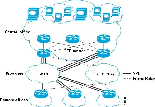
This enhancement allows you to configure two-way VPN optimization. A master controller and border router process are enabled on each side of the VPN. Each site maintains a separate master controller database. VPN routes can be dynamically learned through the tunnel interfaces or can be configured. Prefix and exit link policies are configured for VPN prefixes through a standard Cisco IOS OER configuration.
Protection of Route Prefixes with IPsec over GRE Tunnels
The IPsec-to-GRE model allows a service provider to provide VPN services over the IP backbone. Both the central and remote VPN clients terminate according to the IPsec-to-IPsec model. Prefixes are encapsulated using GRE tunnels. The GRE packet is protected by IPsec. The encapsulated prefixes are forwarded from the central VPN site to a customer headend router that is the other endpoint for GRE. The IPsec-protected GRE packets provide secure connectivity across the IP backbone of the service provider network.
For more information about configuring IPsec over GRE tunnels, see the Dynamic Multipoint IPsec VPNs (Using Multipoint GRE/NHRP to Scale IPsec VPNs) document published at the following URL:
http://www.cisco.com/en/US/tech/tk583/tk372/technologies_white_paper09186a008018983e.shtml
How to Configure VPN IPsec GRE Tunnel Interfaces As OER-Managed Exit Links
Configuring OER to Monitor and Control IPsec VPN Prefixes over GRE Tunnels
Perform this task to configure the IPsec VPN configuration over GRE tunnels. Initially the IPsec VPN is configured on a border router, and the tunnel interface is configured as an OER-managed external interface on the master controller. In this task an IKE policy is defined, a transform set is configured, a crypto profile and a crypto map are defined, and a GRE tunnel is configured.
The GRE tunnel and IPsec protection in this task are configured on the border router. The configuration steps in this task show how to configure a single tunnel. At least two tunnels must be configured on border routers in an OER-managed network. The IPsec configuration must be applied at each tunnel endpoint (the central and remote site).
Configuration of GRE Tunnel Interfaces As OER-Managed Exit Links
GRE tunnel interfaces on the border routers are configured as OER external interfaces on the master controller. At least two external tunnel interfaces must be configured on separate physical interfaces in an OER-managed network. These interfaces can be configured on a single border router or multiple border routers. Internal interfaces are configured normally using a physical interface that is on the border router and is reachable by the master controller.
 Note |
Cisco IOS OER supports only IPsec/GRE VPNs. No other VPN types are supported. |
DETAILED STEPS
Configuration Examples for Configuring VPN IPsec GRE Tunnel Interfaces As OER-Managed Exit Links
Configuring OER to Monitor and Control GRE IPsec VPN Prefixes Example
The figure below shows a central VPN site and two remote VPN sites. VPN peering is established through the service provider clouds. An OER-managed network is configured at each site where Cisco IOS OER configuration is applied independently. Each site has a separate master controller and border router process, and each site maintains a separate master controller database.
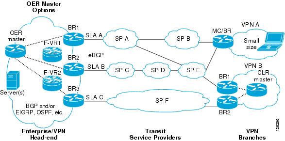
Two GRE tunnels are configured between each remote site and the central site. VPN prefixes are encapsulated in GRE tunnels, which in turn are protected by IPsec encryption. The examples in this section show the configuration for the central VPN site, VPN A, and VPN B.
Central VPN Configuration: OER Master Controller
The central VPN site peers with VPN A and VPN B. A separate policy is defined for each site using an OER map. For VPN A prefixes, a delay policy of 80 ms is configured and out-of-policy prefixes are moved to the first in-policy exit. For VPN B prefixes, a delay policy of 40 ms and a relative loss policy are configured, and out-of-policy prefixes are moved to the best available exit.
key chain OER
 key 1
  key-string CISCO
!
oer master
 logging
 border 10.4.9.6 key-chain OER
  interface Ethernet 0/0 external
  interface Ethernet 0/1 internal
!
 border 10.4.9.7 key-chain OER
  interface Ethernet 0/0 external
  interface Ethernet 0/1 internal
!
 mode route control
 mode monitor both
 exit
!
ip prefix VPN A permit 10.4.9.25
oer-map VPNA
 match ip address prefix-list VPNB
 set delay 800
 set mode select-exit good
 exit
!
ip prefix VPNB permit 10.4.9.254
oer-map VPNB
 match ip address prefix-list VPNC
 set delay 400
 set loss relative 100
 set resolve loss priority 1 variance 10
 set mode select-exit best
 end
Central VPN Configuration: BR1
The following example, starting in global configuration mode, shows the central VPN configuration for BR1:
key chain OER
 key 1
  key-string CISCO
!
oer border
 local serial 0/1
 master 10.4.9.4 key-chain OER
!
ip route 10.70.1.0 255.255.255.0
!
route-map REDISTRIBUTE_STATIC
 match tag 5000
 set metric -10
 exit
!
router eigrp 1
 network 10.70.0.0 0.0.0.255
 redistribute static route-map REDISTRIBUTE_STATIC
 exit
!
crypto ipsec security-association lifetime kilobytes 530000000
crypto ipsec security-association lifetime second 14400
crypto ipsec transform-set VPN_1 esp-3des esp-sha-hmac
 mode transport
 exit
!
crypto map TUNNEL 10 ipsec-isakmp
 set peer 10.4.9.81
 set transform-set VPN_1
 match address 100
!
crypto ipsec profile OER
 set transform-set VPN_1
 exit
crypto map TUNNEL local-address Ethernet 0/0
!
crypto isakmp key 0 CISCO address 10.4.9.81 no-xauth
crypto isakmp keepalive 10
crypto isakmp policy 1
 encryption 3des
 authentication pre-share
 exit
!
interface Ethernet0/0
 ip address 10.4.9.14 255.255.255.0
 crypto map TUNNEL
 exit
!
interface Tunnel0
 ip address 10.100.2.1 255.255.0.0
 keepalive 30 5
 bandwidth 500
 bandwidth inherit
 tunnel mode gre ip
 tunnel source 10.4.9.14
 tunnel destination 10.4.9.81
 tunnel protection ipsec profile OER
 exit
Central VPN Configuration: BR2
The following example, starting in global configuration mode, shows the central VPN configuration of BR2:
key chain OER
 key 1
  key-string CISCO
!
oer border
 local Ethernet 0/1
 master 10.4.9.4 key-chain OER
!
ip route 10.70.1.0 255.255.255.0
!
route-map REDISTRIBUTE_STATIC
 match tag 5000
 set metric -10
 exit
!
router eigrp 1
 network 10.70.0.0 0.0.0.255
 redistribute static route-map REDISTRIBUTE_STATIC
!
crypto ipsec security-association lifetime kilobytes 530000000
crypto ipsec security-association lifetime second 14400
crypto ipsec transform-set VPN_1 esp-3des esp-sha-hmac
 mode transport
 exit
!
crypto map TUNNEL 10 ipsec-isakmp
 set peer 10.4.9.82
 set transform-set VPN_1
 match address 100
!
crypto ipsec profile OER
 set transform-set VPN_1
 exit
crypto map TUNNEL local-address Ethernet 0/0
!
crypto isakmp key 0 CISCO address 10.4.9.82 no-xauth
crypto isakmp keepalive 10
crypto isakmp policy 1
 encryption 3des
 authentication pre-share
 exit
!
interface Ethernet0/0
 ip address 10.4.9.15 255.255.255.0
 crypto map TUNNEL
 exit
!
interface Tunnel0
 ip address 10.100.2.2 255.255.0.0
 keepalive 30 5
 bandwidth 500
 bandwidth inherit
 tunnel mode gre ip
 tunnel source 10.4.9.15
 tunnel destination 10.4.9.82
 tunnel protection ipsec profile OER
 end
Central VPN Configuration: Internal Peers
The following example shows an EIGRP routing process created to establish peering with the border routers and internal peers:
router eigrp 1
 network 10.50.1.0 0.0.0.255
 redistribute static route-map REDISTRIBUTE_STATIC
 end
VPN A Configuration: MC/BR
The following configuration example, starting in global configuration mode, shows the configuration of VPN A. VPN A is a remote site that is configured for a small office home office (SOHO) client. A single router is deployed. This router peers with service provider B and service provider E. No Interior Gateway Protocol (IGP) is deployed at this network; only a static route is configured to the remote tunnel endpoint at the central site. A delay policy, a loss policy, and optimal exit link selection are configured so that traffic is always routed through the ISP with the lowest delay time and lowest packet loss. A resolve policy is configured to configure loss to have the highest priority. Neither the physical interface configuration nor the router IGP peering configurations are shown in this example.
key chain BR1
 key 1
  key-string CISCO
!
Note |
The local border router process is enabled. Because the border router and master controller process is enabled on the same router, a loopback interface (192.168.0.1) is configured as the local interface. |
oer border
 local Loopback0
 master 192.168.0.1 key-chain BR1
!
oer master
 learn
 delay
 mode route control
 delay threshold 100
 loss relative 200
 periodic 300
 mode select-exit good
resolve loss priority 1 variance 20
resolve delay priority 2 variance 10
!
 border 192.168.0.1 key-chain BR1
  interface Serial0/0 internal
  interface Tunnel0 external
  interface Tunnel0 external
  exit
!
crypto ipsec security-association lifetime kilobytes 530000000
crypto ipsec security-association lifetime second 14400
crypto ipsec transform-set VPN_1 esp-3des esp-sha-hmac
 mode transport
 exit
!
crypto map TUNNEL 10 ipsec-isakmp
 set peer 10.4.9.81
 set transform-set VPN_1
 match address 100
!
crypto ipsec profile OER
 set transform-set VPN_1
 exit
crypto map TUNNEL local-address Ethernet 0/0
!
crypto isakmp key 0 CISCO address 10.4.9.81 no-xauth
crypto isakmp keepalive 10
crypto isakmp policy 1
 encryption 3des
 authentication pre-share
 exit
!
interface Ethernet0/0
 ip address 10.4.9.14 255.255.255.0
 crypto map TUNNEL
 exit
!
interface Tunnel0
 ip address 10.100.2.1 255.255.0.0
 keepalive 30 5
 bandwidth 500
 bandwidth inherit
 tunnel mode gre ip
 tunnel source 10.4.9.14
 tunnel destination 10.4.9.81
 tunnel protection ipsec profile OER
 exit
!
Note |
A single tunnel configuration is show in this example. Two tunnels are required to configure VPN optimization. |
VPN B Configuration: OER Master Controller
The following example, starting in global configuration mode, shows the master controller configuration in VPN B. Load distribution and route control mode are enabled. Out-of-policy prefixes are configured to be moved to the first in-policy exit.
key chain OER
 key 1
  key-string CISCO
!
oer master
 logging
 border 10.4.9.6 key-chain OER
  interface Ethernet 0/0 external
  interface Ethernet 0/1 internal
!
 border 10.4.9.7 key-chain OER
  interface Ethernet 0/0 external
  interface Ethernet 0/1 internal
!
mode route control
mode select-exit good
max-range utilization
!
 learn
  delay
  end
VPN B Configuration: BR1
The following example, starting in global configuration mode, shows the VPN B configuration for BR1:
key chain OER
 key 1
  key-string CISCO
!
oer border
 local Ethernet 0/1
 master 10.4.9.4 key-chain OER
!
route-map REDISTRIBUTE_STATIC
 match tag 5000
 set metric -10
 exit
!
router rip
 network 10.60.1.0
 redistribute static route-map REDISTRIBUTE_STATIC
 end
!
crypto ipsec security-association lifetime kilobytes 530000000
crypto ipsec security-association lifetime second 14400
crypto ipsec transform-set VPN_1 esp-3des esp-sha-hmac
 mode transport
 exit
!
crypto map TUNNEL 10 ipsec-isakmp
 set peer 10.4.9.82
 set transform-set VPN_1
 match address 100
!
crypto ipsec profile OER
 set transform-set VPN_1
 exit
crypto map TUNNEL local-address Ethernet 0/0
!
crypto isakmp key 0 CISCO address 10.4.9.82 no-xauth
crypto isakmp keepalive 10
crypto isakmp policy 1
 encryption 3des
 authentication pre-share
 exit
!
interface Ethernet0/0
 ip address 10.4.9.15 255.255.255.0
 crypto map TUNNEL
 exit
!
interface Tunnel0
 ip address 10.100.2.2 255.255.0.0
 keepalive 30 5
 bandwidth 500
 bandwidth inherit
 tunnel mode gre ip
 tunnel source 10.4.9.15
 tunnel destination 10.4.9.82
 tunnel protection ipsec profile OER
 end
VPN B Configuration: BR2
The following example, starting in global configuration mode, shows the VPN B configuration for BR2:
key chain OER
 key 1
  key-string CISCO
!
oer border
 local Ethernet 0/1
 master 10.4.9.4 key-chain OER
 exit
!
route-map REDISTRIBUTE_STATIC
 match tag 5000
 set metric -10
 exit
!
router rip
 network 10.60.1.0
 redistribute static route-map REDISTRIBUTE_STATIC
 exit
!
crypto ipsec security-association lifetime kilobytes 530000000
crypto ipsec security-association lifetime second 14400
crypto ipsec transform-set VPN_1 esp-3des esp-sha-hmac
 mode transport
 exit
!
crypto map TUNNEL 10 ipsec-isakmp
 set peer 10.4.9.82
 set transform-set VPN_1
 match address 100
!
crypto ipsec profile OER
 set transform-set VPN_1
 exit
crypto map TUNNEL local-address Ethernet 0/0
!
crypto isakmp key 0 CISCO address 10.4.9.82 no-xauth
crypto isakmp keepalive 10
crypto isakmp policy 1
 encryption 3des
 authentication pre-share
 exit
!
interface Ethernet0/0
 ip address 10.4.9.15 255.255.255.0
 crypto map TUNNEL
 exit
!
interface Tunnel0
 ip address 10.100.2.2 255.255.0.0
 keepalive 30 5
 bandwidth 500
 bandwidth inherit
 tunnel mode gre ip
 tunnel source 10.4.9.15
 tunnel destination 10.4.9.82
 tunnel protection ipsec profile OER
 end
Where to Go Next
This document describes a specific implementation of OER and presumes that you are familiar with the OER technology. If you want to review more information about OER, proceed to the Cisco IOS Optimized Edge Routing Overview module, followed by the Setting Up OER Network Components module. To learn more about the other OER phases, read through the other modules in the following list:
- Using OER to Profile the Traffic Classes
- Measuring the Traffic Class Performance and Link Utilization Using OER
- Configuring and Applying OER Policies
- Using OER to Control Traffic Classes and Verify the Route Control Changes
After you understand the various OER phases you may want to review other OER Solutions modules that are listed under the Related Documents section.
Additional References
The following sections provide references related to configuring VPN IPsec/GRE tunnel interfaces as OER-managed exit links.
Related Documents
| Related Topic |
Document Title |
|---|---|
| Cisco OER technology overview |
Cisco IOS Optimized Edge Routing Overview module |
| Concepts and configuration tasks required to set up OER network components. |
Setting Up OER Network Components module |
| OER solution module: voice traffic optimization using OER active probes. |
OER Voice Traffic Optimization Using Active Probes module |
| Cisco OER commands: complete command syntax, command mode, command history, defaults, usage guidelines and examples |
Cisco IOS Optimized Edge Routing Command Reference |
| IP Routing Protocol commands |
Cisco IOS IP Routing Protocols Command Reference |
| Key Chain Authentication: information about authentication key configuration and management in Cisco IOS software |
Managing Authentication Keys section of the Configuring IP Routing Protocol-Independent Features chapter in the Cisco IOS IP Routing Protocols Configuration Guide |
Technical Assistance
| Description |
Link |
|---|---|
| The Cisco Support website provides extensive online resources, including documentation and tools for troubleshooting and resolving technical issues with Cisco products and technologies. To receive security and technical information about your products, you can subscribe to various services, such as the Product Alert Tool (accessed from Field Notices), the Cisco Technical Services Newsletter, and Really Simple Syndication (RSS) Feeds. Access to most tools on the Cisco Support website requires a Cisco.com user ID and password. |
Feature Information for Configuring VPN IPsec GRE Tunnel Interfaces As OER-Managed Exit Links
The following table provides release information about the feature or features described in this module. This table lists only the software release that introduced support for a given feature in a given software release train. Unless noted otherwise, subsequent releases of that software release train also support that feature.
Use Cisco Feature Navigator to find information about platform support and Cisco software image support. To access Cisco Feature Navigator, go to http://www.cisco.com/go/cfn. An account on Cisco.com is not required.
Cisco and the Cisco Logo are trademarks of Cisco Systems, Inc. and/or its affiliates in the U.S. and other countries. A listing of Cisco's trademarks can be found at www.cisco.com/go/trademarks. Third party trademarks mentioned are the property of their respective owners. The use of the word partner does not imply a partnership relationship between Cisco and any other company. (1005R)
Any Internet Protocol (IP) addresses and phone numbers used in this document are not intended to be actual addresses and phone numbers. Any examples, command display output, network topology diagrams, and other figures included in the document are shown for illustrative purposes only. Any use of actual IP addresses or phone numbers in illustrative content is unintentional and coincidental.
Copyright © 2010, Cisco Systems, Inc. All rights reserved.
 Feedback
Contact Cisco
- Open a Support Case

- (Requires a Cisco Service Contract)
This Document Applies to These Products
- Collaboration Endpoints - Retired Products
- Conferencing - Retired Products
- Contact Center - Retired Products
- Optical Networking - Retired Products
- Routers - Retired Products
- Security - Retired Products
- Servers - Unified Computing (UCS) Retired Products
- Storage Networking Retired Products
- Switches - Retired Products
- Video - Retired Products
- Wireless - Retired Products