Configure VXLAN

This chapter contains these sections:

Guidelines and Limitations for VXLAN

VXLAN has the following guidelines and limitations:

Switch or port restrictions

  • FEX ports do not support IGMP snooping on VXLAN VLANs.

  • The VXLAN UDP port number is used for VXLAN encapsulation. For Cisco Nexus NX-OS, the UDP port number is 4789. It complies with IETF standards and is not configurable.

  • Cisco Nexus 9300 Series switches with 100G uplinks only support VXLAN switching/bridging.

    Cisco Nexus 9200, Cisco Nexus 9300-EX, and Cisco Nexus 9300-FX, and Cisco Nexus 9300-FX2 platform switches do not have this restriction.


    Note


    For VXLAN routing support, a 40G uplink module is required.
  • When SVI is enabled on a VTEP (flood and learn, or EVPN), make sure that ARP-ETHER TCAM is carved using the hardware access-list tcam region arp-ether 256 command. This requirement does not apply to Cisco Nexus 9200, 9300-EX, 9300-FX/FX2/FX3, and 9300-GX/GX2 platform switches and Cisco 9500 Series switches with 9700-EX/FX/GX line cards.

  • Beginning with Cisco NX-OS Release 10.2(3)F, VXLAN can coexist with the GRE tunnel feature or the MPLS (static or segment-routing) feature.

  • Native VLANs are supported as transit traffic over a VXLAN fabric on Cisco Nexus 9300-EX/FX/FX2/FX3/GX/GX2 Series switches.

  • A FEX HIF (FEX host interface port) is supported for a VLAN that is extended with VXLAN.

  • Bind NVE to a loopback address that is separate from other loopback addresses that are required by Layer 3 protocols. A best practice is to use a dedicated loopback address for VXLAN. This best practice should be applied not only for the vPC VXLAN deployment, but for all VXLAN deployments.

  • Tenant VRF (VRF with VNI on it) cannot be used on an SVI that has no VNI binding into it (underlay infra VRF).

  • For traceroute through a VXLAN fabric when using L3VNI, the following scenario is the expected behavior:

    If L3VNI is associated with a VRF and an SVI, the associated SVI does not have an L3 address that is configured but instead has the "ip forward" configuration command. Due to this interface setup it cannot respond back to the traceroute with its own SVI address. Instead, when a traceroute involving the L3VNI is run through the fabric, the IP address reported will be the lowest IP address of an SVI that belongs to the corresponding tenant VRF.

  • In an ingress replication vPC setup, Layer 3 connectivity is needed between vPC peer devices.

VXLAN configuration restrictions

  • show commands with the internal keyword are not supported.

  • The lacp vpc-convergence command can be configured in VXLAN and non-VXLAN environments that have vPC port channels to hosts that support LACP.

  • For scale environments, the VLAN IDs related to the VRF and Layer-3 VNI (L3VNI) must be reserved with the system vlan nve-overlay id command.

  • The load-share keyword has been added to the Configuring a Route Policy procedure for the PBR over VXLAN feature.

    For information regarding the load-share keyword usage for PBR with VXLAN, see the Guidelines and Limitations for Policy-Based Routing section of the Cisco Nexus 9000 Series NX_OS Unicast Routing Configuration Guide, Release 9.x.

  • The lacp vpc-convergence command is added for better convergence of Layer 2 EVPN VXLAN:

    interface port-channel10
      switchport
      switchport mode trunk
      switchport trunk allowed vlan 1001-1200
      spanning-tree port type edge trunk
      spanning-tree bpdufilter enable
      lacp vpc-convergence  
      vpc 10
     
    interface Ethernet1/34  <- The port-channel member-port is configured with LACP-active mode (for example, no changes are done at the member-port level.)
      switchport
      switchport mode trunk
      switchport trunk allowed vlan 1001-1200
      channel-group 10 mode active
      no shutdown
  • The system nve ipmc command is not applicable to the Cisco Nexus 9200 and 9300-EX platform switches and Cisco Nexus 9500 platform switches with 9700-EX line cards.

  • The VXLAN network identifier (VNID) 16777215 is reserved and should not be configured explicitly.

  • To refresh the frozen duplicate host during fabric forwarding, use only fabric forwarding dup-host-recovery-timer command and do not use fabric forwarding dup-host-unfreeze-timer command, as it is deprecated.

ISSU restrictions

  • VXLAN supports In-Service Software Upgrades (ISSUs). However, VXLAN ISSU is not supported for Cisco Nexus 9300-GX platform switches.

  • To remove configurations from an NVE interface, we recommend manually removing each configuration rather than using the default interface nve command.

  • Rollback is not supported on VXLAN VLANs that are configured with the port VLAN mapping feature.

Feature support and restrictions

  • ACL

    • ACL Options for VXLAN Traffic on Cisco Nexus 92300YC, 92160YC-X, 93120TX, 9332PQ, and 9348GC-FXP Switches.

      ACL Direction

      ACL Type

      VTEP Type

      Port Type

      Flow Direction

      Traffic Type

      Supported

      Ingress

      PACL

      Ingress VTEP

      L2 port

      Access to Network [GROUP:encap direction]

      Native L2 traffic [GROUP:inner]

      YES

      VACL

      Ingress VTEP

      VLAN

      Access to Network [GROUP:encap direction]

      Native L2 traffic [GROUP:inner]

      YES

      Ingress

      RACL

      Ingress VTEP

      Tenant L3 SVI

      Access to Network [GROUP:encap direction]

      Native L3 traffic [GROUP:inner]

      YES

      Egress

      RACL

      Ingress VTEP

      Uplink L3/L3-PO/SVI

      Access to Network [GROUP:encap direction]

      VXLAN encap [GROUP:outer]

      NO

      Ingress

      RACL

      Egress VTEP

      Uplink L3/L3-PO/SVI

      Network to Access [GROUP:decap direction]

      VXLAN encap [GROUP:outer]

      NO

      Egress

      PACL

      Egress VTEP

      L2 port

      Network to Access [GROUP:decap direction]

      Native L2 traffic [GROUP:inner]

      NO

      VACL

      Egress VTEP

      VLAN

      Network to Access [GROUP:decap direction]

      Native L2 traffic [GROUP:inner]

      NO

      Egress

      RACL

      Egress VTEP

      Tenant L3 SVI

      Network to Access [GROUP:decap direction]

      Post-decap L3 traffic [GROUP:inner]

      YES

    • ACL Options for VXLAN traffic on Cisco Nexus 92160YC-X, 93108TC-EX, 93180LC-EX, and 93180YC-EX switches, Release 7.0(3)I6(1).

    • Support added for MultiAuth Change of Authorization (CoA). For more information, see the Cisco Nexus 9000 Series NX-OS Security Configuration Guide, Release 9.3(x).

  • Multicast

    • Beginning with Cisco NX-OS Release 10.3(1)F, the Non-blocking Multicast (NBM) feature and VXLAN can co-exist on the same box but in two different VRFs.


      Note


      Make sure that the NBM is not enabled on the default VRF where underlay runs.


    • NLB in the unicast, multicast, and IGMP multicast modes is not supported on Cisco Nexus 9000 switch VXLAN VTEPs. The work-around is to move the NLB cluster behind the intermediary device (which supports NLB in the respective mode) and inject the cluster IP address as an external prefix into the VXLAN fabric.

    • On Cisco Nexus 9500 Series switches, if feature nv overlay is enabled, ensure that the interface NVE is configured and in UP state. Otherwise, multicast traffic may be silently dropped in Fabric Modules when it needs to be forwarded out of sub-interfaces.

    • If multiple VTEPs use the same multicast group address for underlay multicast but have different VNIs, the VTEPs should have at least one VNI in common. Doing so ensures that NVE peer discovery occurs and underlay multicast traffic is forwarded correctly.

      For example, leafs L1 and L4 could have VNI 10 and leafs L2 and L3 or border spine could have VNI 20, and both VNIs could share the same group address. When leaf L1 sends traffic to leaf L4, the traffic could pass through leaf L2 or L3 or border spine. Because NVE peer L1 is not learned on leaf L2 or L3 or border spine , the traffic is dropped. Therefore, VTEPs that share a group address need to have at least one VNI in common so that peer learning occurs and traffic is not dropped. This requirement applies to VXLAN bud-node topologies and border spine cases.

  • PIM BiDir

    • PIM BiDir for VXLAN underlay with and without vPC is supported.

      The following features are not supported when PIM BiDir for VXLAN underlay is configured:

      • Flood and Learn VXLAN

      • Tenant Routed Multicast (TRM)

      • VXLAN EVPN Multi-Site

      • VXLAN EVPN Multihoming

      • vPC attached VTEPs

      For redundant RPs, use Phantom RP.

      For transitioning from PIM ASM to PIM BiDir or from PIM BiDir to PIM ASM underlay, we recommend that you use the following example procedure:

      no ip pim rp-address 192.0.2.100 group-list 230.1.1.0/8
      clear ip mroute *
      clear ip mroute date-created *
      clear ip pim route *
      clear ip igmp groups *
      clear ip igmp snooping groups * vlan all

      Wait for all tables to clean up.

      ip pim rp-address 192.0.2.100 group-list 230.1.1.0/8 bidir
    • When entering the no feature pim command, NVE ownership on the route is not removed so the route stays and traffic continues to flow. Aging is done by PIM. PIM does not age out entries having a VXLAN encap flag.

  • ARP suppression

    • Beginning with Cisco NX-OS Release 9.3(3), ARP suppression is supported for Cisco Nexus 9300-GX platform switches.

    • Beginning with Cisco NX-OS Release 9.3(5), ARP suppression is supported with reflective relay for Cisco Nexus 9364C, 9300-EX, 9300-FX/FX2/FXP, and 9300-GX platform switches. For information on reflective relay, see the Cisco Nexus 9000 Series NX-OS Layer 2 Switching Configuration Guide.

    • ARP suppression is supported for a VNI only if the VTEP hosts the First-Hop Gateway (Distributed Anycast Gateway) for this VNI. The VTEP and SVI for this VLAN must be properly configured for the Distributed Anycast Gateway operation (for example, global anycast gateway MAC address configured and anycast gateway with the virtual IP address on the SVI).

    • ARP suppression is a per-L2VNI fabric-wide setting in the VXLAN fabric. Enable or disable this feature consistently across all VTEPs in the fabric. Inconsistent ARP suppression configuration across VTEPs is not supported.

  • FCoE/NPV

    Fibre Channel over Ethernet (FCoE) N-port Virtualization (NPV) can coexist with VXLAN on different fabric uplinks but on the same or different front-panel ports on Cisco Nexus 93180YC-EX and 93180YC-FX switches.

    Fibre Channel N-port Virtualization (NPV) can coexist with VXLAN on different fabric uplinks but on the same or different front-panel ports on Cisco Nexus 93180YC-FX switches. VXLAN can exist only on the Ethernet front-panel ports and not on the FC front-panel ports.

  • Subinterfaces

    • Beginning with Cisco NX-OS Release 9.3(5), the subinterfaces on VXLAN uplinks has the ability to carry non-VXLAN L3 IP traffic for Cisco Nexus 9332C, 9364C, 9300-EX, 9300-FX/FX2/FXP, and 9300-GX platform switches and Cisco Nexus 9500 platform switches with -EX/FX line cards. This feature is supported for VXLAN flood and learn and VXLAN EVPN, VXLAN EVPN Multi-Site, and DCI.

    • Beginning with Cisco NX-OS Release 10.1(1), VXLAN-encapsulated traffic over Parent Interface that Carries Subinterfaces is supported on Cisco Nexus 9300-FX3 platform switches.

    • Beginning with Cisco NX-OS Release 9.3(5), VTEPs support VXLAN-encapsulated traffic over parent interfaces if subinterfaces are configured. This feature is supported for VXLAN flood and learn, VXLAN EVPN, VXLAN EVPN Multi-Site, and DCI. As shown in the following configuration example, VXLAN traffic is forwarded on the parent interface (eth1/1) in the default VRF, and L3 IP (non-VXLAN) traffic is forwarded on subinterfaces (eth1/1.10) in the tenant VRF.

      interface ethernet 1/1
       description VXLAN carrying interface
       no switchport
       ip address 10.1.1.1/30
      
      interface ethernet 1/1.10
       description NO VXLAN
       no switchport
       vrf member Tenant10
       encapsulation dot1q 10
        ip address 10.10.1.1/30

Restrictions of Cisco Nexus 9504 and 9508 switches with -R line cards

  • For the Cisco Nexus 9504 and 9508 switches with -R line cards, VXLAN Layer 2 Gateway is supported on the 9636C-RX line card. VXLAN and MPLS cannot be enabled on the Cisco Nexus 9508 switch at the same time.

  • For the Cisco Nexus 9504 and 9508 switches with -R line cards, if VXLAN is enabled, the Layer 2 Gateway cannot be enabled when there is any line card other than the 9636C-RX.

  • For the Cisco Nexus 9504 and 9508 switches with -R line cards, PIM/ASM is supported in the underlay ports. PIM/Bidir is not supported. For more information, see the Cisco Nexus 9000 Series NX_OS Multicast Routing Configuration Guide, Release 9.3(x).

  • For the Cisco Nexus 9504 and 9508 switches with -R line cards, IPv6 hosts routing in the overlay is supported.

  • For the Cisco Nexus 9504 and 9508 switches with -R line cards, ARP suppression is supported.

  • For the Cisco Nexus 9504 and 9508 switches with -R line cards, VXLAN with ingress replication is not supported.

  • VXLAN does not support coexistence with MVR and MPLS for Cisco Nexus 9504 and 9508 with -R line cards.

  • For Cisco Nexus 9504 and 9508 switches with -R line cards, the L3VNI's VLAN must be added on the vPC peer-link trunk's allowed VLAN list.

Not supported features

  • VXLAN is not supported on the Cisco Nexus N9K-C92348GC-X switches.

  • MDP is not supported for VXLAN configurations.

  • Consistency checkers are not supported for VXLAN tables.

  • VTEP connected to FEX host interface ports is not supported.

  • Resilient hashing (port-channel load-balancing resiliency) and VXLAN configurations are not compatible with VTEPs using ALE uplink ports.


    Note


    Resilient hashing is disabled by default.


  • Beginning with Cisco NX-OS Release 10.3(3)F, MHBFD with the new L3VNI mode is not supported on VXLAN.

  • Routing protocol adjacencies using Anycast Gateway SVIs is not supported.

  • RACLs are not supported on Layer 3 uplinks for VXLAN traffic. Egress VACLs support is not available for de-capsulated packets in the network to access direction on the inner payload.

    As a best practice, use PACLs/VACLs for the access to the network direction.

  • The QoS buffer-boost feature is not applicable for VXLAN traffic.

  • The following limitations apply to releases prior to Cisco NX-OS Release 9.3(5):

    • VTEPs do not support VXLAN-encapsulated traffic over subinterfaces, regardless of VRF participation or IEEE 802.1Q encapsulation.

    • VTEPs do not support VXLAN-encapsulated traffic over parent interfaces if subinterfaces are configured, regardless of VRF participation.

    • Mixing subinterfaces for VXLAN and non-VXLAN VLANs is not supported.

  • Point-to-multipoint Layer 3 and SVI uplinks are not supported.

  • SVI and subinterfaces as uplinks are not supported.

Supported Features of CloudScale switches

Table 1. Supported Features of CloudScale switches

Features

Release

Platforms

Limitations

VXLAN

7.0(3)I7(3)

Cisco Nexus 9348GC-FXP switch

Cisco Nexus 9300-EX platform switches

Cisco Nexus 9500 platform switches with 9500-R and 9700-EX, FX line cards

10.2(3)F and later

Cisco Nexus 9500 platform switches with 9700-GX line cards

10.4(1)F and later

Cisco Nexus 9348GC-FX3, 9348GC-FX3PH and 9332D-H2R switches

10.4(2)F and later Cisco Nexus 93400LD-H1 switches
10.4(3)F and later Cisco Nexus 9364C-H1 switches
10.5(2)F and later

Cisco Nexus 9500 Series switches with N9K-X9736C-FX3

  • VXLAN with vPC

  • DHCP snooping, ACL, and QoS policies on VXLAN VLANs.

  • IGMP snooping on VXLAN enabled VLANs.

  • Nested VXLAN (Host Overlay over Network Overlay)

  • PBR with IPv4 underlay

  • NVE source-interface hold-down timer for non-VPC VTEPs

DHCP snooping

Port-VLAN with VXLAN

Cisco Nexus 9300-EX and 9500 Series switches with 9700-EX line cards

  • Only Layer 2 (no routing) is supported with port-VLAN with VXLAN on these switches.

  • No inner VLAN mapping is supported.

ARP suppression

9.3(3) and later

Cisco Nexus 9300-GX platform switches

9.3(5) and later

Cisco Nexus 9364C, 9300-EX, 9300-FX/FX2/FXP, and 9300-GX platform switches

supported with reflective relay. For information on reflective relay, see the Cisco Nexus 9000 Series NX-OS Layer 2 Switching Configuration Guide.

ITD and ePBR over VXLAN

10.1(1) and later

N9K-X9716D-GX TOR and N9K-C93180YC-FX3S platform switches.

PBR over VXLAN

10.1(1) and later

N9K-C9316D-GX, N9K-C93600CD-GX, and N9K-C9364C-GX

VXLAN flood and learn mode

9.3(6) and later

Cisco Nexus 9300-GX platform switches

10.1(1) and later

N9K-C9316D-GX, N9K-C93600CD-GX, and N9K-C9364C-GX TOR switches.

BFD multihop over VXLAN with L3VNI interfaces

10.4(1)F and later

Border Spine 10.4(3)F and later Cisco Nexus 9800 switches For more information on the supported and not supported features, see Supported platforms and configuration guidelines for VXLAN EVPN Multi-Site and Supported platforms, software versions, and features for TRM with Multi-Site.

VXLAN deployment requirements and platform support

This topic summarizes the technical requirements, platform-specific configurations, system routing modes, and resource allocation necessary for successful VXLAN deployments on Cisco Nexus platforms.

Resource reservation and system routing modes

  • For scale environments, the VLAN IDs related to the VRF and Layer-3 VNI (L3VNI) must be reserved with the system vlan nve-overlay id command.

    This optimizes VXLAN resource allocation on these platforms:

    • Cisco Nexus 9300 platform switches

    • Cisco Nexus 9500 platform switches with 9500 line cards

    The system vlan nve-overlay id command applies only to VRF or Layer-3 VNI VLANs, not to regular VLANs or Layer-2 VNIs.

    system vlan nve-overlay id 2000
            
            vlan 2000
              vn-segment 50000
            
            interface Vlan2000
              vrf member MYVRF_50000
              ip forward
              ipv6 forward
            
            vrf context MYVRF_50000
              vni 50000
  • The "System Routing Mode: Default" is applicable is supported on:

    • Cisco Nexus 9200 platform switches

    • Cisco Nexus 9300 platform switches

    • Cisco Nexus 9300-EX platform switches

    • Cisco Nexus 9300-FX/FX2/FX3 platform switches

    • Cisco Nexus 9300-GX platform switches

    • Cisco Nexus 9500 platform switches with X9500 line cards

    • Cisco Nexus 9500 platform switches with X9700-EX/FX line cards

  • The “System Routing Mode: template-vxlan-scale” is not applicable.

  • When using VXLAN BGP EVPN in combination with Cisco NX-OS Release 7.0(3)I4(x) or NX-OS Release 7.0(3)I5(1), the “System Routing Mode: template-vxlan-scale” is required on these platforms:

    • Cisco Nexus 9300-EX Switches

    • Cisco Nexus 9500 Switches with X9700-EX line cards

  • Changing the “System Routing Mode” requires a reload of the switch.

Dual-stack host scale and scalability

Support for the extended dual-stack-host-scale template for ARP, ND, and MAC is available on these platforms and software versions:

  • Beginning with Cisco NX-OS Release 10.3(1)F, supported on the Cisco Nexus 9300-FX3/GX/GX2B ToR switches.

  • The system routing template-dual-stack-host-scale command is used to scale ARP and ND. Platform-specific scaling limits are documented in the Cisco Nexus 9000 Series NX-OS Verified Scalability Guide.

Loopback and interface requirements

  • The source-interface config command references a loopback address to represent the local VTEP IP.

  • During switch boot-up, the source-interface hold-down-time <hold-down-time> command suppresses advertisement of the NVE loopback address until overlay convergence. Supported hold-down time ranges from 0 to 2,147,483,647 seconds (default: 300 seconds).


    Note


    If the loopback interface is down, traffic may still be encapsulated and sent to the fabric.


  • When changing a VTEP device’s IP address, the NVE interface is typically shut down before making the change.

  • During the migration of VTEPs to a multisite BGW, the NVE interface on all relevant VTEPs is administratively shut during migration, and brought up after the multisite configuration is completed.

Multicast, PIM, and RP requirements

  • For establishing IP multicast routing in the core, configure IP multicast, PIM, and RP.

  • Configure the RP for multicast groups only on the spine layer. Use the anycast RP for RP load balancing and redundancy.

    Example anycast RP configuration on spines:

    ip pim rp-address 198.51.100.10 group-list 224.0.0.0/4   
    ip pim anycast-rp 198.51.100.10 198.51.100.1
    ip pim anycast-rp 198.51.100.10 198.51.100.2 

    Note


    • 198.51.100.10 is the anycast RP IP address that is configured on all RPs participating in the anycast RP set.

    • 198.51.100.1 is the local RP IP.

    • 198.51.100.2 is the peer RP IP.


Gateway design and VTEP considerations

  • In VXLAN flood and learn mode, the default gateway for VXLAN VLAN is implemented as a centralized gateway on a pair of vPC devices with FHRP (First Hop Redundancy Protocol) running.

  • VTEP-to-VTEP unicast reachability is provided through any IGP protocol.

  • For VXLAN EVPN:

    • Any SVI for a VLAN extended over VXLAN is configured with anycast gateway.

    • Other modes of operation are not supported.

    If one VTEP has an L2VNI with anycast gateway enabled, every other VTEP with that L2VNI locally defined also configures the SVI with anycast gateway.

  • In flood and learn mode, only a centralized Layer 3 gateway is supported; anycast gateway is not supported. The recommended Layer 3 gateway design is a pair of switches in vPC acting as the Layer 3 centralized gateway with FHRP protocol on the SVI. The same SVI cannot span multiple VTEPs, even with different IP addresses in the same subnet.


    Note


    When configuring SVI with flood and learn mode on the central gateway leaf, the hardware access-list tcam region arp-ether <size> double-wide command is used (the size of an existing TCAM region must be decreased first).

    For example:

    hardware access-list tcam region arp-ether 256 double-wide 


    Note


    Configuring the hardware access-list tcam region arp-ether size double-wide is not required on Cisco Nexus 9200 Series switches.


ARP/ND scaling and TCAM configuration

  • For BGP-EVPN ARP suppression, the hardware access-list tcam region arp-ether size double-wide command allocates the required TCAM region. Reducing the size of an existing TCAM region may be necessary first.


    Note


    • This step is required for Cisco Nexus 9300 switches (NFE/ALE) and Cisco Nexus 9500 switches with N9K-X9564PX, N9K-X9564TX, and N9K-X9536PQ line cards.

    • This step is not needed with Cisco Nexus 9200 switches, Cisco Nexus 9300-EX switches, or Cisco Nexus 9500 switches with N9K-X9732C-EX line cards.


VXLAN tunnel and replication requirements

  • VXLAN tunnels have a single underlay next hop per underlay port. On any given output underlay port, only one destination MAC address is used as the outer MAC. This is a per-port limitation, meaning two tunnels reachable through the same underlay port cannot use separate outer MAC addresses.

  • Static ingress replication and BGP EVPN ingress replication do not require any IP Multicast routing in the underlay.

vPC Considerations for VXLAN Deployment

  • As a best practice, when feature vpc is enabled or disabled on a VTEP, the NVE interfaces on both the vPC primary and the vPC secondary must be shut down before the change is made. Enabling feature vpc without the vPC domain being properly configured will result in the NVE loopback being held administratively down until the configuration is completed and the vPC peer-link is brought up.

  • Bind NVE to a loopback address that is separate from other loopback addresses that are required by Layer 3 protocols. A best practice is to use a dedicated loopback address for VXLAN.

  • On vPC VXLAN, it is recommended to increase the delay restore interface-vlan timer under the vPC configuration, if the number of SVIs are scaled up. For example, if there are 1000 VNIs with 1000 SVIs, we recommend to increase the delay restore interface-vlan timer to 45 seconds.

  • If a ping is initiated to the attached hosts on VXLAN VLAN from a vPC VTEP node, the source IP address used by default is the anycast IP that is configured on the SVI. This ping can fail to get a response from the host in case the response is hashed to the vPC peer node. This issue can happen when a ping is initiated from a VXLAN vPC node to the attached hosts without using a unique source IP address. As a workaround for this situation, use VXLAN OAM or create a unique loopback on each vPC VTEP and route the unique address via a backdoor path.

  • The loopback address used by NVE needs to be configured to have a primary IP address and a secondary IP address.

    The secondary IP address is used for all VXLAN traffic that includes multicast and unicast encapsulated traffic.

  • vPC peers must have identical configurations.

    • Consistent VLAN to vn-segment mapping.

    • Consistent NVE1 binding to the same loopback interface

      • Using the same secondary IP address.

      • Using different primary IP addresses.

    • Consistent VNI to group mapping.

  • For multicast, the vPC node that receives the (S, G) join from the RP (rendezvous point) becomes the DF (designated forwarder). On the DF node, encap routes are installed for multicast.

    Decap routes are installed based on the election of a decapper from between the vPC primary node and the vPC secondary node. The winner of the decap election is the node with the least cost to the RP. However, if the cost to the RP is the same for both nodes, the vPC primary node is elected.

    The winner of the decap election has the decap mroute installed. The other node does not have a decap route installed.

  • On a vPC device, BUM traffic (broadcast, unknown-unicast, and multicast traffic) from hosts is replicated on the peer-link. A copy is made of every native packet and each native packet is sent across the peer-link to service orphan-ports connected to the peer vPC switch.

    To prevent traffic loops in VXLAN networks, native packets ingressing the peer-link cannot be sent to an uplink. However, if the peer switch is the encapper, the copied packet traverses the peer-link and is sent to the uplink.


    Note


    Each copied packet is sent on a special internal VLAN (VLAN 4041 or VLAN 4046).


  • When the peer-link is shut, the loopback interface used by NVE on the vPC secondary is brought down and the status is Admin Shut. This is done so that the route to the loopback is withdrawn on the upstream and that the upstream can divert all traffic to the vPC primary.


    Note


    Orphans connected to the vPC secondary will experience loss of traffic for the period that the peer-link is shut. This is similar to Layer 2 orphans in a vPC secondary of a traditional vPC setup.


  • When the vPC domain is shut, the loopback interface used by NVE on the VTEP with shutdown vPC domain is brought down and the status is Admin Shut. This is done so that the route to the loopback is withdrawn on the upstream and that the upstream can divert all traffic to the other vPC VTEP.

  • When peer-link is no-shut, the NVE loopback address is brought up again and the route is advertised upstream, attracting traffic.

  • For vPC, the loopback interface has two IP addresses: the primary IP address and the secondary IP address.

    The primary IP address is unique and is used by Layer 3 protocols.

    The secondary IP address on loopback is necessary because the interface NVE uses it for the VTEP IP address. The secondary IP address must be same on both vPC peers.

  • The vPC peer-gateway feature must be enabled on both peers to facilitate NVE RMAC/VMAC programming on both peers. For peer-gateway functionality, at least one backup routing SVI is required to be enabled across peer-link and also configured with PIM. This provides a backup routing path in the case when VTEP loses complete connectivity to the spine. Remote peer reachability is re-routed over peer-link in his case. In BUD node topologies, the backup SVI needs to be added as a static OIF for each underlay multicast group.

    switch# sh ru int vlan 2
    
    interface Vlan2
     description backupl_svi_over_peer-link
     no shutdown
     ip address 30.2.1.1/30
     ip router ospf 1 area 0.0.0.0
     ip pim sparse-mode
     ip igmp static-oif route-map match-mcast-groups
    
     route-map match-mcast-groups permit 1
      match ip multicast group 225.1.1.1/32
    

    Note


    In BUD node topologies, the backup SVI needs to be added as a static OIF for each underlay multicast group.

    The SVI must be configured on both vPC peers and requires PIM to be enabled.


  • When the NVE or loopback is shut in vPC configurations:

    • If the NVE or loopback is shut only on the primary vPC switch, the global VXLAN vPC consistency checker fails. Then the NVE, loopback, and vPCs are taken down on the secondary vPC switch.

    • If the NVE or loopback is shut only on the secondary vPC switch, the global VXLAN vPC consistency checker fails. Then, the NVE, loopback, and secondary vPC are brought down on the secondary. Traffic continues to flow through the primary vPC switch.

    • As a best practice, you should keep both the NVE and loopback up on both the primary and secondary vPC switches.

  • Redundant anycast RPs configured in the network for multicast load-balancing and RP redundancy are supported on vPC VTEP topologies.

  • As a best practice, when changing the secondary IP address of an anycast vPC VTEP, the NVE interfaces on both the vPC primary and the vPC secondary must be shut before the IP changes are made.

  • When SVI is enabled on a VTEP (flood and learn, or EVPN) regardless of ARP suppression, make sure that ARP-ETHER TCAM is carved using the hardware access-list tcam region arp-ether 256 double-wide command. This requirement does not apply to Cisco Nexus 9200, 9300-EX, and 9300-FX/FX2/FX3 and 9300-GX/GX2 platform switches and Cisco Nexus 9500 platform switches with 9700-EX line cards.

  • The show commands with the internal keyword are not supported.

  • DHCP snooping (Dynamic Host Configuration Protocol snooping) is not supported on VXLAN VLANs.

  • RACLs are not supported on Layer 3 uplinks for VXLAN traffic. Egress VACLs support is not available for de-capsulated packets in the network to access direction on the inner payload.

    As a best practice, use PACLs/VACLs for the access to the network direction.

    See the Cisco Nexus 9000 Series NX-OS Security Configuration Guide, Release 9.3(x) for other guidelines and limitations for the VXLAN ACL feature.

  • QoS classification is not supported for VXLAN traffic in the network to access direction on the Layer 3 uplink interface.

    See the Cisco Nexus 9000 Series NX-OS Quality of Service Configuration Guide, Release 9.3(x) for other guidelines and limitations for the VXLAN QoS feature.

  • The QoS buffer-boost feature is not applicable for VXLAN traffic.

  • Beginning with Cisco NX-OS Release 9.3(5), VTEPs support VXLAN-encapsulated traffic over parent interfaces if subinterfaces are configured.

  • VTEPs do not support VXLAN encapsulated traffic over subinterfaces. This is regardless of VRF participation or IEEE802.1Q encapsulation.

  • Mixing subinterfaces for VXLAN and non-VXLAN VLANs is not supported.

  • Point-to-multipoint Layer 3 and SVI uplinks are not supported.

  • Using the ip forward command enables the VTEP to forward the VXLAN de-capsulated packet destined to its router IP to the SUP/CPU.

  • Before configuring it as an SVI, the backup VLAN needs to be configured on Cisco Nexus 9200, 9300-EX, and 9300-FX/FX2/FX3 and 9300-GX platform switches as an infra-VLAN with the system nve infra-vlans command.

  • VXLAN is supported on Cisco Nexus 9500 platform switches with the following line cards:

    • 9700-EX

    • 9700-FX

    • 9700-GX

  • When Cisco Nexus 9500 platform switches are used as VTEPs, 100G line cards are not supported on Cisco Nexus 9500 platform switches. This limitation does not apply to a Cisco Nexus 9500 switch with 9700-EX or -FX line cards.

  • Cisco Nexus 9300 platform switches with 100G uplinks only support VXLAN switching/bridging. Cisco Nexus 9200 and Cisco Nexus 9300-EX/FX/FX2 platform switches do not have this restriction.


    Note


    For VXLAN routing support, a 40 G uplink module is required.


  • The VXLAN UDP port number is used for VXLAN encapsulation. For Cisco Nexus NX-OS, the UDP port number is 4789. It complies with IETF standards and is not configurable.

  • For Cisco Nexus 9200 platform switches that have the Application Spine Engine (ASE2). There exists a Layer 3 VXLAN (SVI) throughput issue. There is a data loss for packets of sizes 99 - 122.

  • The VXLAN network identifier (VNID) 16777215 is reserved and should not be configured explicitly.

  • VXLAN supports In Service Software Upgrade (ISSU).

  • VXLAN ISSU is not supported on the Cisco Nexus 9300-GX platform switches.

  • VXLAN does not support coexistence with the GRE tunnel feature or the MPLS (static or segment routing) feature.

  • VTEP connected to FEX host interface ports is not supported.

  • Resilient hashing (port-channel load-balancing resiliency) and VXLAN configurations are not compatible with VTEPs using ALE uplink ports.


    Note


    Resilient hashing is disabled by default.


  • When ARP suppression is enabled or disabled in a vPC setup, a down time is required because the global VXLAN vPC consistency checker will fail and the VLANs will be suspended if ARP suppression is disabled or enabled on only one side.


Note


For information about VXLAN BGP EVPN scalability, see the Cisco Nexus 9000 Series NX-OS Verified Scalability Guide, Release 9.3(x).


VXLAN network requirements

VXLAN network requirements are deployment considerations that

  • increase the transport network’s MTU size to accommodate VXLAN header overhead

  • require ECMP and LACP hashing algorithms to use the UDP source port for optimal load-sharing, and

  • address multicast group scaling to balance control plane scalability with data plane efficiency.

Supporting reference information for VXLAN network requirements

The following are important considerations for VXLAN deployments:

  • MTU Size in the Transport Network: Due to MAC-to-UDP encapsulation, VXLAN adds a 50-byte overhead to frames. The transport network’s MTU must be increased by 50 bytes to support this. For overlays using a 1500-byte MTU, configure the transport network for at least 1550 bytes per packet. Jumbo frame support is needed if overlay applications use frames larger than 1500 bytes.

  • ECMP and LACP Hashing Algorithms in the Transport Network: Cisco Nexus 9000 Series Switches introduce entropy in the source UDP port for ECMP and LACP hashing. For best VXLAN load-sharing, ECMP or LACP hashing algorithms must use the UDP source port as input, achieving optimal distribution of VXLAN-encapsulated traffic.

  • Multicast Group Scaling: Cisco Nexus 9000 Series Switches use multicast tunnels for forwarding broadcast, unknown unicast, and multicast traffic in VXLAN. Ideally, each VXLAN segment maps to a single IP multicast group for optimal forwarding. However, multiple segments can share one group to conserve control plane resources, which impacts data plane efficiency by sending packets for one tenant to others sharing the group. The VTEP checks the VNID on incoming packets, forwarding only when the VNID matches a local VXLAN segment, maintaining Layer 2 isolation between tenants.

  • If the overlay MTU is 1500 bytes, configure the transport network MTU to at least 1550 bytes.

  • Mapping multiple VXLAN segments to a single multicast group improves scalability but reduces forwarding efficiency.

Mapping several VXLAN segments to one multicast group is like sharing a single delivery route with multiple destinations: cost and resources are saved, but each package may be delivered to more addresses than needed, leading to inefficiencies.

VXLAN transport network configuration requirements

VXLAN transport network configuration has specific requirements and constraints for ensuring correct operation. These requirements cover VTEP device configuration, transport network behaviors, and the use of VLANs and infra-VLANs.

VTEP device requirements

  • Enable and configure IP multicast.*

  • Create and configure a loopback interface with a /32 IP address.

    (For vPC VTEPs, you must configure primary and secondary /32 IP addresses.)

  • Enable IP multicast on the loopback interface.*

  • Advertise the loopback interface /32 addresses through the routing protocol (static route) that runs in the transport network.

  • Enable IP multicast on the uplink outgoing physical interface.*


Note


* Not required for static ingress replication or BGP EVPN ingress replication.


Transport network configuration

  • Throughout the transport network, enable and configure IP multicast.*

VLAN and infra-VLAN requirements

  • For Cisco Nexus 9200, 9300-EX, and 9300-FX/FX2/FX3 and 9300-GX platform switches, the use of the system nve infra-vlans command is required. Otherwise, VXLAN traffic (IP/UDP 4789) is actively treated by the switch. The following scenarios are a non-exhaustive list but most commonly seen, where the need for a system nve infra-vlans definition is required.

Scenarios requiring infra-VLAN configuration:

For every VLAN not associated with a VNI (vn-segment), configure it as an infra-VLAN in the following cases:

  • In the case of VXLAN flood and learn as well as VXLAN EVPN, the presence of non-VXLAN VLANs could be related to:

    • An SVI related to a non-VXLAN VLAN is used for backup underlay routing between vPC peers via a vPC peer-link (backup routing).

    • An SVI related to a non-VXLAN VLAN is required for connecting downstream routers (external connectivity, dynamic routing over vPC).

    • An SVI related to a non-VXLAN VLAN is required for per Tenant-VRF peering (L3 route sync and traffic between vPC VTEPs in a Tenant VRF).

    • An SVI related to a non-VXLAN VLAN is used for first-hop routing toward endpoints (Bud-Node).

  • In the case of VXLAN flood and learn, the presence of non-VXLAN VLANs could be related to:

    • An SVI related to a non-VXLAN VLAN is used for an underlay uplink toward the spine (Core port).

  • The rule of defining VLANs as system nve infra-vlans can be relaxed for special cases such as:

    • An SVI related to a non-VXLAN VLAN that does not transport VXLAN traffic (IP/UDP 4789).

    • Non-VXLAN VLANs that are not associated with an SVI or not transporting VXLAN traffic (IP/UDP 4789).

Nested VXLAN overlays

A nested VXLAN overlay is a network virtualization mechanism that

  • enables host-originated VXLAN tunnels (inner VXLAN) to be transported across existing VXLAN BGP EVPN data center fabrics (outer VXLAN)

  • supports transparent integration between host overlays and base network overlays with automatic detection and handling of different VXLAN profiles, and

  • provides attachment flexibility for both Layer 2 and Layer 3 interfaces, supporting untagged and tagged traffic across various port types.

Nested VXLAN Support and Platform Information

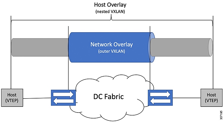
DC Fabrics with VXLAN BGP EVPN are becoming the transport infrastructure for overlays. These overlays, often originated on the server (Host Overlay), require integration or transport over the top of the existing transport infrastructure (Network Overlay).

Nested VXLAN (Host Overlay over Network Overlay) support has been added starting with Cisco NX-OS Release 7.0(3)I7(4) and Cisco NX-OS Release 9.2(2) on the Cisco Nexus 9200, 9300-EX, 9300-FX, 9300-FX2, 9500-EX, 9500-FX platform switches. It is also supported for Cisco Nexus 9300-FX3 platform switches starting with Cisco NX-OS Release 9.3(5).

Nested VXLAN is not supported on a Layer 3 interface or a Layer 3 port-channel interface in Cisco NX-OS Release 9.3(4) and prior releases. It is supported on a Layer 3 interface or a Layer 3 port-channel interface from Cisco NX-OS Release 9.3(5) onwards.

Figure 1. Host Overlay

To provide Nested VXLAN support, the switch hardware and software must differentiate between two different VXLAN profiles:

  • VXLAN originated behind the Hardware VTEP for transport over VXLAN BGP EVPN (nested VXLAN)

  • VXLAN originated behind the Hardware VTEP to integrated with VXLAN BGP EVPN (BUD Node)

The detection of the two different VXLAN profiles is automatic and no specific configuration is needed for nested VXLAN. As soon as VXLAN encapsulated traffic arrives in a VXLAN enabled VLAN, the traffic is transported over the VXLAN BGP EVPN enabled DC Fabric.

The following attachment modes are supported for Nested VXLAN:

  • Untagged traffic (in native VLAN on a trunk port or on an access port)

  • Tagged traffic Layer 2 ports (tagged VLAN on a IEEE 802.1Q trunk port)

  • Untagged and tagged traffic that is attached to a vPC domain

  • Untagged traffic on a Layer 3 interface or a Layer 3 port-channel interface

  • Tagged traffic on Layer 3 interface or a Layer 3 port-channel interface

Configuring VXLAN

Enabling VXLAN functionality

Enable VXLAN functionality on your switch to support network segmentation and overlay tunneling.

VXLAN allows scalable Layer 2 networks to be built over existing Layer 3 infrastructure, enabling network segmentation and elasticity in modern data center environments.

Before you begin

  • Ensure you have administrator access to the switch.

  • Confirm that your device model and software support VXLAN overlays.

Procedure


Step 1

Enter global configuration mode.

Example:

switch# configure terminal

Step 2

Enable the VXLAN overlay feature.

Example:

switch(config)# feature nv overlay

Step 3

Configure the global VXLAN bridge domain mode.

Example:

 switch(config)# feature vn-segment-vlan-based

Step 4

(Optional) Save the configuration to make the changes persistent.

Example:

switch# copy running-config startup-config

VXLAN overlay and bridge domain features are activated, and your configuration changes are saved.

Map a VLAN to a VXLAN VNI

Use this task when you are configuring VXLAN overlays and need to associate specific VLANs with VNIs on your network devices.

Follow these steps to map a VLAN to a VXLAN VNI:

Before you begin

  • Verify that VXLAN is supported and enabled on your device.

  • Make sure you have the VLAN ID and VNI values you want to use.

Procedure


Step 1

Enter global configuration mode.

Example:

switch# configure terminal

Step 2

Specify the VLAN you want to map.

Example:

switch# vlan 100

Step 3

Assign the VXLAN VNI to the VLAN.

Example:

switch# vn-segment 5000

This command associates VLAN 100 with VXLAN VNI 5000

Step 4

Exit configuration mode.

Example:

switch# exit

VLAN 100 is now mapped to VXLAN VNI 5000. Devices in VLAN 100 can now communicate across the VXLAN overlay network using VNI 5000.

Create and configure an NVE interface and associate VNIs

NVE (Network Virtualization Edge) interfaces terminate VXLAN tunnels on the switch. Associating VNIs enables the switch to map tenant or segment traffic across the overlay. This task is for VXLAN-enabled switches in enterprise or data center networks.

Follow these steps to create and configure an NVE interface and associate VNIs:

Before you begin

  • Configure a loopback interface with a unique /32 IP address.

  • Advertise this loopback IP address so it is reachable by remote VTEPs via a dynamic routing protocol (such as OSPF or BGP).

Procedure


Step 1

Enter global configuration mode.

Example:

switch# configure terminal

Step 2

Create the NVE interface.

Example:

switch(config)# interface nve1

Creates a VXLAN overlay interface that terminates VXLAN tunnels.

Note


Only one NVE interface is allowed on the switch.

Step 3

Specify the loopback source interface for the NVE.

Example:

switch(config-if-nve)# source-interface loopback0

The source interface must be a loopback interface that is configured on the switch with a valid /32 IP address. This /32 IP address must be known by the transient devices in the transport network and the remote VTEPs. This is accomplished by advertising it through a dynamic routing protocol in the transport network.

Step 4

Associate one or more VNIs with the NVE interface.

Example:

switch(config-if-nve)# member vni 5000

Step 5

Assign a multicast group for BUM (Broadcast, Unknown Unicast, Multicast) traffic.

Example:

To assign multicast group 239.1.1.1 to VNI 5000

Assign a multicast group to the VNIs.

Note


The multicast group is only needed for BUM traffic


The NVE interface is created and configured; associated VNIs and multicast groups are activated. VXLAN tunnels can now terminate on this switch, segmenting overlay traffic according to the configured VNIs.

Configure a VXLAN VTEP in vPC

Enable VXLAN Virtual Tunnel Endpoint (VTEP) functionality with high availability using a vPC pair.

This configuration is required to provide redundancy and scalability for overlay networks in a Cisco data center fabric.

Follow these steps to configure a VXLAN VTEP in vPC:

Before you begin

  • Ensure device interconnections and peer interfaces are cabled.

  • Gather all IP addresses, VLAN IDs, and domain numbers needed.

Procedure


Step 1

Enable required features.

Enter global configuration mode and enable vPC, interface VLAN, LACP, PIM, and OSPF features:

Example:

switch# configure terminal
switch(config)# feature vpc
switch(config)# feature interface-vlan
switch(config)# feature lacp
switch(config)# feature pim
switch(config)# feature ospf

Step 2

Define a PIM RP address for the underlay multicast group range.

switch(config)# ip pim rp-address 192.168.100.1 group-list 224.0.0/4 

Step 3

Configure the infra-VLAN and SVI

Example:

switch(config)# system nve infra-vlans 10
switch(config)# vlan 10
switch(config)# interface vlan 10
switch(config-if)# ip address 10.10.10.1/30
switch(config-if)# ip router ospf UNDERLAY area 0
switch(config-if)# ip pim sparse-mode
switch(config-if)# no ip redirects
switch(config-if)# mtu 9216
(Optional)switch(config-if)# ip igmp static-oif route-map match-mcast-groups
switch(config-if)# no shutdown
(Optional)switch(config)# route-map match-mcast-gropus permit 10
(Optional)switch(config-route-map)# match ip multicast group 225.1.1.1/32

Step 4

Configure loopback interfaces

  1. Create primary and secondary IP addresses.

    Example:

    switch(config)# interface loopback 0
    switch(config-if)# description Control_plane_Loopback
    switch(config-if)# ip address x.x.x.x/32
    switch(config-if)# ip router ospf process tag area area id
    switch(config-if)# ip pim sparse-mode
    switch(config-if)# no shutdown                            
  2. Create a primary IP address for the data plane loopback interface.

    Example:

    switch(config)# interface loopback 1
    switch(config-if)# description Data_Plane_loopback
    switch(config-if)# ip address z.z.z.z/32
    switch(config-if)# ip address y.y.y.y/32 secondary
    switch(config-if)# ip router ospf process tag area area id
    switch(config-if)# ip pim sparse-mode
    switch(config-if)# no shutdown

Step 5

Create and configure the vPC domain:

switch(config)# vpc domain 5
switch(config-vpc-domain)# peer-keepalive destination 172.28.230.85

Note


The system does not form the vPC peer link until you configure a vPC peer-keepalive link

The management ports and VRF are the defaults.

Note


We recommend that you configure a separate VRF and use a Layer 3 port from each vPC peer device in that VRF for the vPC peer-keepalive link. For more information about creating and configuring VRFs, see the Cisco Nexus 9000 Series NX-OS Unicast Routing Configuration Guide.

Step 6

Enable vPC Peer-Gateway, Peer-switch, and synchronization features:

Example:

switch(config-vpc-domain)# peer-gateway
switch(config-vpc-domain)# peer-switch
switch(config-vpc-domain)# ip arp synchronize
switch(config-vpc-domain)# ipv6 nd synchronize

Example:

Note


Disable IP redirects on all interface-vlans of this vPC domain for correct operation of this feature.

Step 7

Create the vPC peer-link port-channel interface and add two member interfaces.

switch(config)# interface port-channel 1
switch(config-if)# switchport
switch(config-if)# switchport mode trunk
switch(config-if)# switchport trunk allowed vlan 1,10,100-200
switch(config-if)# mtu 9216
switch(config-if)# vpc peer-link
switch(config-if)# no shutdown
switch(config-if)# interface Ethernet 1/1 , 1/21
switch(config-if)# switchport
switch(config-if)# mtu 9216
switch(config-if)# channel-group 1 mode active
switch(config-if)# no shutdown

Step 8

Tune STP timers for optimal convergence:

Example:

switch(config)# spanning-tree vlan 1-3967 hello-time 4
switch(config)# spanning-tree vlan 1-3967 forward-time 30
switch(config)# spanning-tree vlan 1-3967 max-age 40

Example:

As a best practice, we recommend changing the hello-time to four seconds to avoid unnecessary TCN generation when the vPC role change occurs. As a result of changing the hello-time, it is also recommended to change the max-age and forward-time accordingly.

Step 9

(Optional) Configure delay restore timers and additional best practices

We recommend that you tune this value when the SVI or VNI scale is high. For example, when the SVI count is 1000, we recommended setting the delay restore for interface-vlan to 45 seconds.

switch(config-vpc-domain)# delay restore interface-vlan 45

VXLAN VTEP is successfully configured with high availability in a vPC pair, providing a resilient and scalable foundation for overlay networking.

Configure static MAC for VXLAN VTEP

Configure static MAC addresses for VXLAN VTEP on Cisco Nexus 9300 Series switches with flood and learn.

Static MAC for VXLAN VTEP is supported on Cisco Nexus 9300 Series switches with flood and learn. This feature enables the configuration of static MAC addresses behind a peer VTEP.


Note


Static MAC cannot be configured for a control plane with a BGP EVPN-enabled VNI.


Follow these steps to configure static MAC addresses for VXLAN VTEP:

Before you begin

  • Ensure VXLAN flood and learn mode is enabled.

  • Make sure you have the MAC, VNI ID, NVE interface number, and remote VTEP IP address details available.

Procedure


Step 1

Enter global configuration mode.

Example:

switch# configure terminal

Step 2

Configure the static MAC address, associating it with a VNI, interface, and remote VTEP.

Example:

switch(config)# mac address-table static 0047.1200.0000 vni 501 interface nve 1 peer-ip 33.1.1.3

Step 3

Exit global configuration mode.

Example:

switch(config)# exit

Step 4

(Optional) Save the configuration so it persists after reloads.

Example:

switch# copy running-config startup-config

Saves the change persistently through reboots and restarts by copying the running configuration to the startup configuration.

Step 5

(Optional) Verify the static MAC addresses configured for remote VTEPs.

Example:

switch# show mac address-table static interface nve 1
Legend: 
        * - primary entry, G - Gateway MAC, (R) - Routed MAC, O - Overlay MAC
        age - seconds since last seen,+ - primary entry using vPC Peer-Link,
        (T) - True, (F) - False
   VLAN     MAC Address      Type      age     Secure NTFY Ports
---------+-----------------+--------+---------+------+----+------------------
*  501     0047.1200.0000   static   -         F      F    nve1(33.1.1.3)
*  601     0049.1200.0000   static   -         F      F    nve1(33.1.1.4)

Your switch uses the configured static MAC-to-VTEP mapping for VXLAN forwarding. The configuration is immediately effective and, if saved, persists through reloads.

Disable VXLANs

Permanently disable VXLAN-related features on your Cisco switch or device to revert to traditional Layer 2/3 forwarding.

Use this procedure if you are decommissioning VXLANs, reverting network virtualization, or troubleshooting issues that require all VXLAN-related features to be off.

Follow these steps to disable VXLANs.

Before you begin

  • Ensure you have administrator (privileged exec) access to the device’s CLI.

  • Review network dependencies to confirm that disabling VXLAN will not interrupt critical services.

Procedure


Step 1

Enter global configuration mode.

Example:

switch# configure terminal

Step 2

Disable VN-segment VLAN-based feature globally.

Example:

switch(config)# no feature vn-segment-vlan-based

Step 3

(Optional) Save the configuration so it persists after reloads.

Example:

switch# copy running-config startup-config

Saves the change persistently through reboots and restarts by copying the running configuration to the startup configuration.


VXLAN features are now fully disabled on your device. The actions persist after device reboots.

Configure BGP EVPN ingress replication

Enable BGP EVPN with ingress replication for VXLAN peers so network traffic is replicated among VTEPs based on BGP information.

Use this task to set up VXLAN overlay networks with BGP EVPN, allowing efficient traffic replication and dynamic membership among endpoints in large-scale data center or campus fabrics.

Follow these steps to configure BGP EVPN ingress replication:

Before you begin

  • Ensure a loopback interface is configured with an appropriate /32 IP address.

  • Confirm the loopback address is advertised and reachable via dynamic routing protocols (for example, OSPF or BGP).

  • Make sure your switch supports VXLAN and BGP EVPN features.

Procedure


Step 1

Enter global configuration mode.

Example:

switch# configure terminal

Step 2

Create a VXLAN Network Virtualization Edge (NVE) interface.

Example:

switch(config)# interface nve1

Creates a VXLAN overlay interface that terminates VXLAN tunnels.

Note


Only one NVE interface is allowed on the switch.

Step 3

Specify the source interface as the loopback interface.

Example:

switch(config-if)# source-interface loopback0

The source interface must be a loopback interface that is configured on the switch with a valid /32 IP address. This /32 IP address must be known by the transient devices in the transport network and the remote VTEPs. This is accomplished by advertising it through a dynamic routing protocol in the transport network.

Step 4

Associate one or more VXLAN VNIs with the NVE interface.

Example:

switch(config-if)# member vni 5000

Step 5

Enable ingress replication using BGP for each VNI.

Example:

switch(config-if-vni)# ingress-replication protocol bgp

BGP EVPN ingress replication is enabled. VXLAN traffic for configured VNIs will be automatically replicated to remote endpoints (VTEPs) based on dynamic BGP membership, supporting scalable and efficient multicast-free network operation.

Configure static ingress replication

Set up static ingress replication for VXLAN peers to enable multicast traffic forwarding through statically configured peer IP addresses.

Static ingress replication is used in VXLAN environments where multicast is not available or desired. This task configures the necessary parameters on a Cisco switch.

Follow these steps to configure static ingress replication:

Before you begin

  • Make sure you have administrative access to the switch.

  • Know the VXLAN Network Identifier (VNI) values and the peer IP addresses you want to configure.

  • Access the switch through its CLI.

Procedure


Step 1

Enter global configuration mode.

Example:

switch# configure terminal

Step 2

Create a VXLAN Network Virtualization Edge (NVE) interface.

Example:

switch(config)# interface nve1
switch(config-if)#

Creates a VXLAN overlay interface that terminates VXLAN tunnels.

Note


Only one NVE interface is allowed on the switch.

Step 3

Map one or more VNIs to the NVE interface.

Example:

switch(config-if)# member vni 5000

Step 4

Enable static ingress replication for the chosen VNI(s).

Example:

switch(config-if-vni)# ingress-replication protocol static

Enables static ingress replication for the VNI.

Step 5

Specify the peer IP addresses for replication

Example:

switch(config-if-vni)# peer-ip 192.0.2.1

Static ingress replication is enabled for the specified VNI(s). Multicast traffic will be replicated to each configured peer IP address.

  • Configuring a single VNI with one peer IP:
    interface nve1
    member vni 5000
    ingress-replication protocol static
    peer-ip 192.0.2.1
  • Configuring a range of VNIs with multiple peers:
    interface nve1
    member vni 5000-5010
    ingress-replication protocol static
    peer-ip 192.0.2.1
    peer-ip 192.0.2.2
    peer-ip 192.0.2.3

VXLAN and IP-in-IP tunnels

A VXLAN and IP-in-IP tunnel is a network overlay encapsulation method that

  • supports coexistence of distinct tunneling technologies within the same network

  • allows traffic segregation by assigning each tunnel type to a specific VRF, and

  • enables flexible configuration by supporting both tunnel types over shared physical uplinks using subinterfaces and parent interfaces.

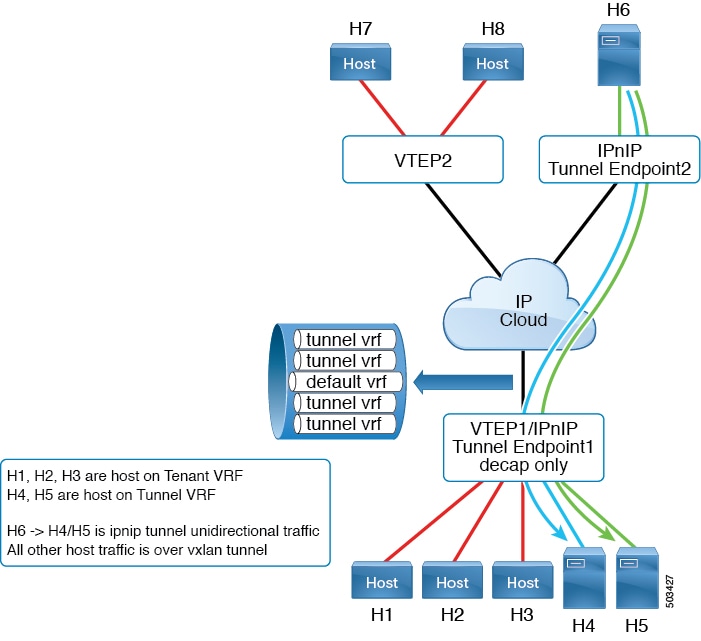
A port-channel subinterface is a logical division of a physical port-channel interface that can belong to a single, non-default VRF for IP-in-IP tunnel termination. Multiple subinterfaces from different parent port-channels may be assigned to the same VRF, but multiple subinterfaces under one port-channel cannot terminate IP-in-IP tunnels in different VRFs. This limitation does not apply to Layer 3 physical ports.

Coexistence limitations and requirements

Cisco NX-OS Release 9.3(6) and later allow VXLAN and IP-in-IP tunnels to coexist on the same device, especially in Nexus 9300-FX2 series switches. These key limitations and requirements apply:

  • VXLAN must be configured in the default VRF.

  • Coexistence is supported only for VXLAN with the EVPN control plane.

  • IP-in-IP tunneling must be configured in a non-default VRF and only supports decapsulate-any mode.

  • Attempting to enable VXLAN while a decapsulate-any tunnel exists in the default VRF generates an error, indicating that coexistence is only supported with decapsulate-any tunnels in non-default VRFs.

  • Point-to-point GRE tunnels are not supported when enabling coexistence.

  • When configuring a decapsulate-any tunnel, only a source IP or interface is required (no remote endpoint). The tunnel terminates on any IP interface in that VRF.

  • Tunnel statistics do not support egress counters.

  • VXLAN and IP-in-IP tunnels cannot share the same source loopback interface; each requires its own source loopback.

VXLAN traffic is forwarded on the parent interface (for example, eth1/1) in the default VRF, and IP-in-IP traffic is forwarded on subinterfaces (such as eth1/1.10) in the tunnel VRF.

Figure 2. Sample configuration for VXLAN and IP-in-IP tunnel coexistence
Sample configuration for coexistence:
feature vn-segment-vlan-based
feature nv overlay
feature tunnel
nv overlay evpn

interface ethernet 1/1
    description VXLAN carrying interface
    no switchport
    ip address 192.0.2.0/30

interface ethernet 1/1.10
    description IPinIP carrying interface
    no switchport
    vrf member tunnel
    encapsulation dot1q 100
    ip address 192.0.2.2/30

interface loopback 0
    description VXLAN-loopback
    ip address 198.51.100.10/32

interface loopback 100
    description Tunnel_loopback
    vrf member tunnel
    ip address 203.0.113.5/32

interface Tunnel1
    vrf member tunnel
    ip address 203.0.113.55/24
    tunnel mode ipip decapsulate-any ip
    tunnel source loopback100
    tunnel use-vrf tunnel
    no shutdown

interface nve1
    host-reachability protocol bgp
    source-interface loopback0
    global mcast-group 224.1.1.1 L2
    global mcast-group 225.3.3.3 L3
    member vni 10000
    suppress-arp
    ingress-replication protocol bgp
    member vni 55500 associate-vrf

Configuring VXLAN Static Tunnels

VXLAN static tunnels

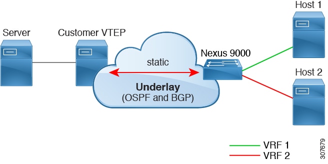
A VXLAN static tunnel is a network overlay technology that

  • allows customer-defined, manually configured tunnels between a Cisco Nexus switch and a software

  • supports VXLAN-encapsulated traffic between hosts without requiring a control plane protocol such as BGP EVPN, and

  • enables each VRF to have a dedicated L3VNI for proper encapsulation and decapsulation between the switch and the static peer.

Because the customer provides the static peer and no control plane protocol is present, the static peer must correctly forward VXLAN-related configuration and routes to the appropriate hosts.

Additional reference information

  • Static tunnels are supported per VRF, and each VRF can have a dedicated L3VNI for traffic encapsulation and decapsulation.

  • The static peer is often a Cisco Nexus 1000V or a bare-metal server with one or more VMs terminating one or more VNIs. However, any customer-developed device adhering to RFC 7348 (VXLAN: A Framework for Overlaying Virtualized Layer 2 Networks over Layer 3 Networks) can function as a static peer.

  • Static tunnels can be configured manually from the Nexus switch or programmatically, for example using a NETCONF client in the underlay.

Example

Beginning with Cisco NX-OS Release 9.3(5), VXLAN static tunnels support bidirectional handling of packets entering and exiting the tunnel, allowing Nexus switches to send packets to hosts or other switches over the tunnel. In Cisco NX-OS Releases 9.3(3) and 9.3(4), VXLAN static tunnels support traffic only from the local host to the remote host.

Figure 3. VXLAN Static Tunnel Connecting Software VTEP

Supported platforms and limitations for VXLAN static tunnels

The VXLAN static tunnels feature has these guidelines and limitations.

Supported platforms and software releases

  • The Cisco Nexus 9332C, 9364C, 9300-EX, and 9300-FX/FX2/FX3, 9300-GX and 9300-FX3 platform switches support VXLAN static tunnels.

  • Beginning with Cisco NX-OS Release 10.1(1), VXLAN Static Tunnels are supported on Cisco Nexus 9300-FX3 platform switches.

  • Beginning with Cisco NX-OS Release 10.2(3)F, the VXLAN Static Tunnels are supported on Cisco Nexus 9300-GX2 platform switches.

Software VTEP requirements

  • The software VTEP must be configured as needed to determine how to forward traffic from the VNI.

  • The software VTEP must be compliant with RFC 7348.

Underlay and overlay network support

  • The underlay can be OSPFv2, BGP, IS-IS, or IPv4.

  • The overlay can be IPv4 only.

Unsupported features and restrictions

  • Additional VXLAN features (such as TRM, Multi-Site, OAM, Cross Connect, and VXLAN QoS), IGMP snooping, MPLS handoff, static MPLS, SR, and SRv6 are not supported.

  • Pings across the overlay from local tenant VRF loopback to a host behind the software VTEP is not supported.

  • Static tunnels do not support ECMP configuration.

  • Static tunnels cannot be configured in the same fabric as traditional flood and learn or BGP EVPN fabrics.

  • Local hosts are not supported for VNI-enabled VLANs. Therefore, you cannot have a host in the same VLAN where you configured the VNI.

Fabric forwarding considerations

When fabric forwarding is enabled with static tunnels:

  • all SVIs where fabric forwarding mode anycast-gateway is configured (for example, Vlan802) are used.

  • the MAC address configured with fabric forwarding anycast-gateway-mac anycast-mac-address (0000.0a0a.0a0a) is used.

Example configuration:
feature fabric forwarding
fabric forwarding anycast-gateway-mac 0000.0a0a.0a0a

interface Vlan802
no shutdown
vrf member vrfvxlan5201
ip address 192.0.2.1/16
fabric forwarding mode anycast-gateway

Enable VXLAN static tunnels

Configure VXLAN static tunnels to support overlay network connectivity using static parameters on Cisco switches.

Use this task to enable the required features for static VXLAN tunnels before configuring overlay VLAN and routing.

Follow these steps to enable VXLAN static tunnels:

Before you begin

Make sure you have administrator access to the switch CLI.

Procedure


Step 1

Enter global configuration mode.

Example:

switch# configure terminal
switch(config)#

Step 2

Enable the VN-Segment feature for VLAN-based VXLAN.

Example:

switch(config)# feature vn-segment
switch(config)#

Step 3

Enable the OFM (OpenFabric Manager) feature to support static VXLAN tunnels:

Example:

switch(config)# feature ofm
switch(config)#

VXLAN static tunnel features are enabled and the device is ready for static VXLAN configuration.

What to do next

Configure the VRF overlay VLAN for VXLAN routing over Static Tunnels.

Configure a VRF overlay for static tunnels

Configure a VRF overlay to enable VXLAN static tunneling.

Before you configure VXLAN routing over static tunnels, you must define a VLAN and assign a VN segment to create the VRF overlay.

Follow these steps to configure the VRF overlay for static tunnels:

Procedure


Step 1

Enter configuration mode on the switch.

Example:

switch# configure terminal
switch(config)#

Step 2

Create a VLAN to serve as the overlay.

Example:

switch(config)# vlan 2001
switch(config-vlan)#

Step 3

Assign a VN segment to the VLAN.

Example:

switch(config-vlan)# vn-segment 20001
switch(config-vlan)#

The VRF overlay is configured and ready for VXLAN routing over static tunnels.

What to do next

Configure the VRF for VXLAN Routing over the Static Tunnel.

Configure a VRF for VXLAN routing

This task guides you through creating a tenant Virtual Routing and Forwarding (VRF) instance and associating it with a VXLAN Network Identifier (VNI), which is required for VXLAN routing in your network.

Configure a tenant VRF when you need to provide network segmentation and enable Layer 3 routing for multiple tenants using VXLAN in your data center. This setup isolates tenant traffic and allows scalable multi-tenant architectures.

Before you begin

  • You have administrative privileges on the switch.

  • You are in global configuration mode.

  • You have the list of tenant VRF names and corresponding VNIs to be configured.

Procedure


Step 1

Enter VRF configuration mode and specify the tenant VRF name.

Example:

switch(config-vlan)# vrf context cust1
switch(config-vrf)# 

This creates a new VRF instance for the tenant and enters VRF configuration mode.

Step 2

Assign a VXLAN Network Identifier (VNI) to the tenant VRF.

Example:

switch(config-vrf)# vni 20001
switch(config-vrf)#

This maps the VRF to a specific VXLAN VNI for Layer 3 routing.


The tenant VRF is now configured and associated with a VNI, enabling VXLAN routing for the specified tenant in your network.

What to do next

  • Configure the Layer 3 VNI interface and connect hosts or gateway devices as needed to complete the VXLAN routing setup.

Configure the L3 VNI for static tunnels

Complete this task to establish L3 VNI connectivity between VTEPs over static tunnels.

Perform this configuration when creating or modifying a VXLAN network that uses static tunnels for Layer 3 segmentation.

Before you begin

Ensure the VLAN interface feature is enabled: feature interface-vlan

Procedure


Step 1

Enter VLAN configuration mode for the L3 VNI VLAN number.

Example:

switch(config-vrf)# vlan 2001
switch(config-vlan)# 

This VLAN will be used for the L3 VNI interface.

Step 2

Enter the VLAN interface configuration mode.

Example:

switch(config)# interface vlan2001
switch(config-if)# 

This creates or modifies the interface for the specified VLAN.

Step 3

Assign the VLAN interface to the tenant VRF using the vrf member command.

Example:

switch(config-if)# vrf member cust1
Warning: Deleted all L3 config on interface Vlan2001
switch(config-if)# 

Binds the VLAN interface to the specified virtual routing and forwarding instance.

Step 4

Enable IPv4 forwarding on the interface.

Example:

switch(config-if)# ip forward
switch(config-if)# 

This allows Layer 3 packet forwarding for the VLAN interface.

Step 5

Enable the VLAN interface.

Example:

switch(config-if)# no shutdown
switch(config-if)# 

Activates the VLAN interface for network traffic.


The L3 VNI VLAN interface is created and configured for use with static tunnels. Layer 3 connectivity for the specified VNI is now available between VTEPs.

What to do next

Proceed to configure the tunnel profile as required for your VXLAN deployment.

Configure the tunnel profile

Use this task to set up a tunnel profile that enables static VXLAN tunnels by specifying interfaces and endpoints.

Configure a tunnel profile when you need to establish static tunnels on a Nexus switch, specifying the source interface, encapsulation type, and remote endpoint details. This configuration ensures proper communication over static VXLAN tunnels.

Before you begin

Before you begin, ensure:

  • The underlay network is fully configured and operational.

  • You have administrative access to the Nexus device CLI.

  • You have identified the MAC address and interface details of the static peer.

Procedure


Step 1

Enter tunnel profile configuration mode and specify a profile name.

Example:

switch(config)# tunnel-profile test
switch(config-tnl-profile)#

Step 2

Set the encapsulation type for the tunnel profile.

Example:

switch(config-tnl-profile)# encapsulation vxlan
switch(config-tnl-profile)#

Note


In NX-OS release 9.3(3), only the vxlan encapsulation type is supported.

Step 3

Specify the loopback interface as the source for the tunnel profile.

Example:

switch(config-tnl-profile)# source-interface loopback 1
switch(config-tnl-profile)#

Note


The loopback interface number must be between 0 and 1023.

Step 4

Configure the tunnel route, specifying destination VRF, destination host prefix, destination VTEP IP address, next-hop VRF, VNI, and the destination VTEP MAC address.

Example:

switch(tunnel-profile)# route vrf cust1 192.0.2.2/32 198.51.100.1 next-hop-vrf default vni 20001 dest-vtep-mac f80f.6f43.036c
switch(tunnel-profile)#

Note


The route vrf command accepts one destination-vtep-mac-address per destination-vtep-ip-address across all the routes. If you configure additional routes, they are cached as errored routes and a error syslog is generated for each.


The tunnel profile is configured, enabling static VXLAN tunnels between the Nexus switch and the specified peer.

What to do next

Verify tunnel functionality by sending traffic and checking endpoint connectivity. Review syslog messages for route errors if multiple MAC addresses are configured for a single VTEP IP.

Verify VXLAN static tunnels

Use this task to confirm that VXLAN static tunnels are correctly configured, operational, and to identify any tunnel reachability or configuration issues.

VXLAN static tunnels remain in the configuration even if a tunnel endpoint (VTEP) goes down. Traffic is dropped while a VTEP is unreachable, but service resumes once connectivity is restored and the underlay network relearns the route. Use the following commands to verify tunnel state and assist with troubleshooting.

Before you begin

Ensure you have CLI access to the device and the necessary privileges to run show commands.

Procedure


Step 1

Run the show tunnel-profile command to view the configuration and status of VXLAN tunnel profiles.

This shows information about the tunnel profiles configured for the software.

Step 2

Run the show ip route tenant-vrf-name command to check routing information for the VRF associated with the VXLAN tunnel.

If you receive a "route unreachable" error, use this command to verify the route exists for the VRF's tunnel destination.

Step 3

Run the show running-config ofm command to display the running configuration for the Overlay Forwarding Module (OFM) and static tunnels.

Use this command to confirm that the destination VTEP route is present in the configuration.


VXLAN static tunnels are verified as operational, or you identify specific configuration or reachability issues for troubleshooting.

What to do next

To further troubleshoot tunnel traffic, use SPAN to monitor relevant switch ports and source VLANs.

VXLAN static tunnel configuration example

This reference provides a sample configuration for establishing a VXLAN static tunnel using supported methods. It demonstrates how to create a VLAN, associate it with a VXLAN network segment (VN-Segment), configure the corresponding virtual interface and VRF, and define a tunnel profile for static VXLAN encapsulation.

Key configuration elements

  • VLAN and VN-Segment association: Creates VLAN 2001 and maps it to VN-Segment 20001.

  • Virtual interface and VRF assignment: Configures interface Vlan2001, enables it, assigns it to VRF “cust1”, and turns on IP forwarding.

  • VRF context mapping: Defines VRF context “cust1” with a corresponding VXLAN Network Identifier (VNI) 20001.

  • VXLAN static tunnel profile: Enables the VXLAN feature, then creates a tunnel profile with encapsulation settings, source interface, routing, and specifies the destination VTEP MAC address.

Configuration example:
vlan 2001
vlan 2001
  vn-segment 20001
 
interface Vlan2001
  no shutdown
  vrf member cust1
  ip forward

vrf context cust1
  vni 20001


feature ofm

tunnel-profile test
  encapsulation vxlan
  source-interface loopback1
   route vrf cust1 192.0.2.2/32 203.0.113.1 next-hop-vrf default vni 20001 dest-vtep-mac f80f.6f43.036c
Apply this configuration to establish a static VXLAN tunnel for a segmented customer network (VRF “cust1”), allowing direct mapping of endpoint IP addresses to a specific destination VTEP using the specified tunnel profile. This approach is used when dynamic VXLAN peer discovery is not required or supported.