Configuring Bud Node

This chapter contains these sections:

VXLAN Bud Nodes

Figure 1. Underlay Network Based on PIM-SM and OSPF

Note


For bud-node topologies, the source IP of the VTEP behind vPC must be in the same subnet as the infra VLAN. This SVI should have proxy ARP enabled. For example:


Interface Vlan2 
ip proxy-arp


Note


The system nve infra-vlans command specifies VLANs used for all SVI interfaces, for uplink interfaces with respect to bud-node topologies, and vPC peer-links in VXLAN as infra-VLANs. You must not configure certain combinations of infra-VLANs. For example, 2 and 514, 10 and 522, which are 512 apart.

For Cisco Nexus 9200, 9300-EX, and 9300-FX/FX2/FX3 and 9300-GX platform switches, use the system nve infra-vlans command to configure any VLANs that are used as infra-VLANs.


VXLAN Bud Node Over vPC Topology Examples

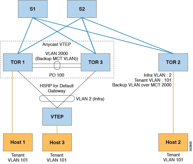
VXLAN Bud Node over vPC topology provides a configuration example for deploying VXLAN with vPC and Bud Node functionality.

  • Enable the required features:

    
    feature ospf
    feature pim
    feature interface-vlan
    feature vn-segment-vlan-based
    feature hsrp
    feature lacp
    feature vpc
    feature nv overlay
    
    
  • Configuration for PIM anycast RP. In this example, 1.1.1.1 is the anycast RP address.

    
    ip pim rp-address 1.1.1.1 group-list 225.0.0.0/8
    
    
  • VLAN configuration. In this example, tenant VLANs 101-103 are mapped to vn-segments.

    
    vlan 1-4,101-103,2000
    vlan 101
      vn-segment 10001
    vlan 102
      vn-segment 10002
    vlan 103
      vn-segment 10003
    
    
  • vPC configuration

    
    vpc domain 1
      peer-switch
      peer-keepalive destination 172.31.144.213
      delay restore 180
      peer-gateway
      ipv6 nd synchronize
      ip arp synchronize
    
    
  • Infra VLAN SVI configuration

    
    interface Vlan2
      no shutdown
      no ip redirects
      ip proxy-arp
      ip address 10.200.1.252/24
      no ipv6 redirects
      ip router ospf 1 area 0.0.0.0
      ip pim sparse-mode
      ip igmp static-oif route-map match-mcast-groups
      hsrp version 2
      hsrp 1 
        ip 10.200.1.254
    
    
  • Route-maps for matching multicast groups. Each VXLAN multicast group needs to have a static OIF on the backup SVI MCT.

    
    route-map match-mcast-groups permit 1
      match ip multicast group 225.1.1.1/32
    
    
  • Backup SVI over MCT configuration

    • Configuration Option 1:

      
      interface Vlan2000
      no shutdown
      ip address 20.20.20.1/24
      ip router ospf 1 area 0.0.0.0
      ip pim sparse-mode
      
      
    • Configuration Option 2:

      
      interface Vlan2000
      no shutdown
      ip address 20.20.20.1/24
      ip router ospf 1 area 0.0.0.0
      ip pim sparse-mode
      
      
  • vPC interface configuration that carries the infra VLAN

    
    interface port-channel1
      switchport mode trunk
      switchport trunk allowed vlan 2
      vpc 1
    
    
  • MCT configuration

    
    interface port-channel100
      switchport mode trunk
      spanning-tree port type network
      vpc peer-link


Note


You can choose either of the following two command procedures for creating the NVE interfaces. Use the first one for a small number of VNIs. Use the second procedure to configure a large number of VNIs.


NVE configuration

Option 1


interface nve1
  no shutdown
  source-interface loopback0
  member vni 10001 mcast-group 225.1.1.1
  member vni 10002 mcast-group 225.1.1.1
  member vni 10003 mcast-group 225.1.1.1

Option 2


interface nve1
  no shutdown
  source-interface loopback0
  global mcast-group 225.1.1.1
  member vni 10001
  member vni 10002 
  member vni 10003 

Loopback interface configuration


interface loopback0
  ip address 101.101.101.101/32
  ip address 99.99.99.99/32 secondary
  ip router ospf 1 area 0.0.0.0
  ip pim sparse-mode

Show commands


tor1# sh nve vni 
Codes: CP - Control Plane        DP - Data Plane          
       UC - Unconfigured         SA - Suppress ARP
       
Interface VNI      Multicast-group   State Mode Type [BD/VRF]      Flags
--------- -------- ----------------- ----- ---- ------------------ -----
nve1      10001    225.1.1.1         Up    DP   L2 [101]                
nve1      10002    225.1.1.1         Up    DP   L2 [102]                
nve1      10003    225.1.1.1         Up    DP   L2 [103]               

tor1# sh nve peers 
Interface Peer-IP          State LearnType Uptime   Router-Mac       
--------- ---------------  ----- --------- -------- -----------------
nve1      10.200.1.1       Up    DP        00:07:23 n/a              
nve1      10.200.1.2       Up    DP        00:07:18 n/a              
nve1      102.102.102.102  Up    DP        00:07:23 n/a      


tor1# sh ip mroute 225.1.1.1
IP Multicast Routing Table for VRF "default"

(*, 225.1.1.1/32), uptime: 00:07:41, ip pim nve static igmp 
  Incoming interface: Ethernet2/1, RPF nbr: 10.1.5.2
  Outgoing interface list: (count: 3)
    Vlan2, uptime: 00:07:23, igmp
    Vlan2000, uptime: 00:07:31, static
    nve1, uptime: 00:07:41, nve

(10.200.1.1/32, 225.1.1.1/32), uptime: 00:07:40, ip mrib pim nve 
  Incoming interface: Vlan2, RPF nbr: 10.200.1.1
  Outgoing interface list: (count: 3)
    Vlan2, uptime: 00:07:23, mrib, (RPF)
    Vlan2000, uptime: 00:07:31, mrib
    nve1, uptime: 00:07:40, nve

(10.200.1.2/32, 225.1.1.1/32), uptime: 00:07:41, ip mrib pim nve 
  Incoming interface: Vlan2, RPF nbr: 10.200.1.2
  Outgoing interface list: (count: 3)
    Vlan2, uptime: 00:07:23, mrib, (RPF)
    Vlan2000, uptime: 00:07:31, mrib
    nve1, uptime: 00:07:41, nve

(99.99.99.99/32, 225.1.1.1/32), uptime: 00:07:41, ip mrib pim nve 
  Incoming interface: loopback0, RPF nbr: 99.99.99.99
  Outgoing interface list: (count: 3)
    Vlan2, uptime: 00:07:23, mrib
    Vlan2000, uptime: 00:07:31, mrib
    Ethernet2/5, uptime: 00:07:39, pim
(102.102.102.102/32, 225.1.1.1/32), uptime: 00:07:40, ip mrib pim nve 
  Incoming interface: Ethernet2/1, RPF nbr: 10.1.5.2
  Outgoing interface list: (count: 1)
    nve1, uptime: 00:07:40, nve


tor1# sh vpc
Legend:
                 - local vPC is down, forwarding via vPC peer-link

vPC domain id                     : 1   
Peer status                       : peer adjacency formed ok      
vPC keep-alive status             : peer is alive                 
Configuration consistency status  : success 
Per-vlan consistency status       : success                       
Type-2 consistency status         : success 
vPC role                          : secondary, operational primary
Number of vPCs configured         : 4   
Peer Gateway                      : Enabled
Dual-active excluded VLANs        : -
Graceful Consistency Check        : Enabled
Auto-recovery status              : Disabled
Delay-restore status              : Timer is off.(timeout = 180s)
Delay-restore SVI status          : Timer is off.(timeout = 10s)

vPC Peer-link status
---------------------------------------------------------------------
id   Port   Status Active vlans    
--   ----   ------ --------------------------------------------------
1    Po100  up     1-4,101-103,2000                                       

vPC status
----------------------------------------------------------------------
id   Port   Status Consistency Reason                     Active vlans
--   ----   ------ ----------- ------                     ------------
1    Po1    up     success     success                    2               
                                                                          
2    Po2    up     success     success                    2  

tor1# sh vpc consistency-parameters global 

    Legend:
        Type 1 : vPC will be suspended in case of mismatch

Name                        Type  Local Value            Peer Value             
-------------               ----  ---------------------- -----------------------
Vlan to Vn-segment Map      1     3 Relevant Map(s)      3 Relevant Map(s)     
STP Mode                    1     Rapid-PVST             Rapid-PVST            
STP Disabled                1     None                   None                  
STP MST Region Name         1     ""                     ""                    
STP MST Region Revision     1     0                      0                     
STP MST Region Instance to  1                                                  
 VLAN Mapping                                                                  
STP Loopguard               1     Disabled               Disabled              
STP Bridge Assurance        1     Enabled                Enabled               
STP Port Type, Edge         1     Normal, Disabled,      Normal, Disabled,     
BPDUFilter, Edge BPDUGuard        Disabled               Disabled              
STP MST Simulate PVST       1     Enabled                Enabled               
Nve Oper State, Secondary   1     Up, 99.99.99.99, DP    Up, 99.99.99.99, DP   
IP, Host Reach Mode                                                            
Nve Vni Configuration       1     10001-10003            10001-10003           
Interface-vlan admin up     2     2,2000                 2,2000                
Interface-vlan routing      2     1-4,2000               1-4,2000              
capability                                                                     
Allowed VLANs               -     1-4,101-103,2000       1-4,101-103,2000      
Local suspended VLANs       -     -