Configure Tenant Routed Multicast

This chapter contains these sections:

Tenant Routed Multicast

A Tenant Routed Multicast (TRM) is a VXLAN EVPN multicast forwarding solution that

  • enables efficient multicast delivery across a multi-tenant VXLAN fabric using a BGP-based EVPN control plane

  • supports multicast forwarding between senders and receivers within the same or different subnets and VTEPs, and

  • improves Layer-3 overlay multicast scalability and efficiency for modern data center networks.

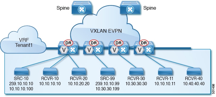
Tenant routed multicast brings standards-based multicast capabilities to the VXLAN overlay network by leveraging next generation multicast VPN (ngMVPN) as described in IETF RFC 6513 and 6514. TRM allows each edge device (VTEP) with a distributed IP Anycast Gateway to also act as a Designated Router (DR) for multicast forwarding. Bridged multicast forwarding is optimized through IGMP snooping, ensuring only interested receivers at the edge receive the multicast traffic, while all non-local multicast traffic is routed for efficient delivery.

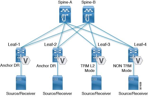
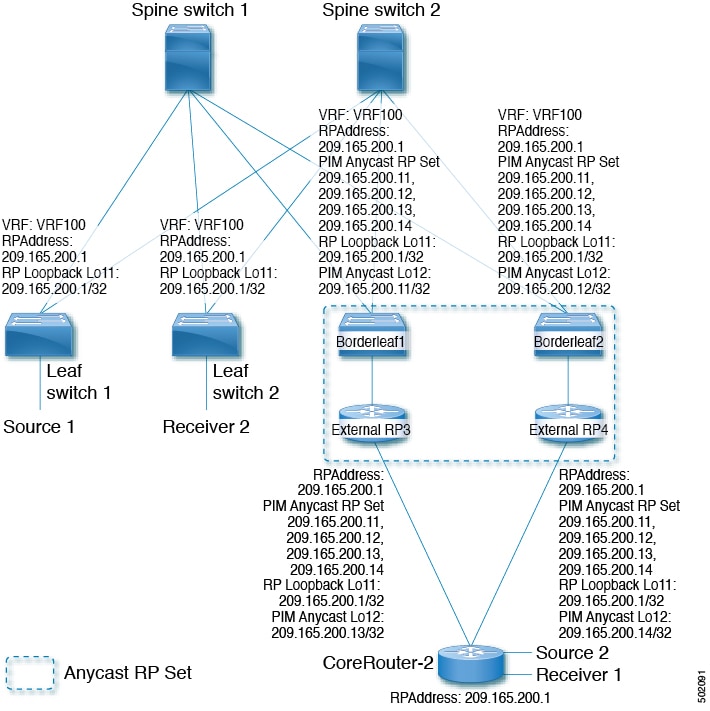
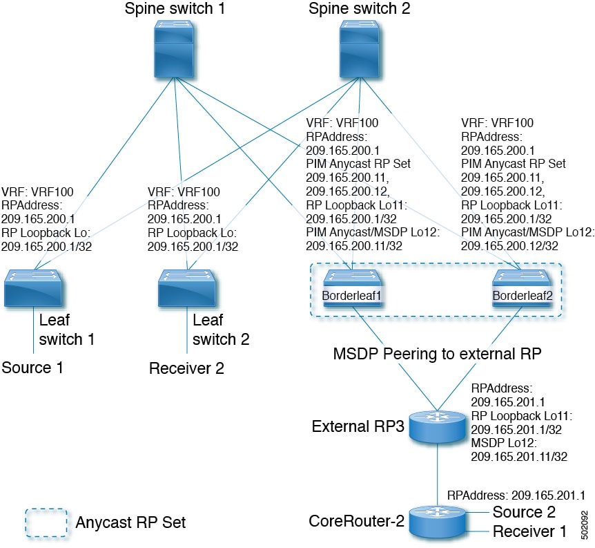
When TRM is enabled, multicast forwarding in the underlay network is used to replicate VXLAN-encapsulated routed multicast traffic. A Default Multicast Distribution Tree (Default-MDT) is built per VRF, which supplements the existing multicast groups for Layer-2 VNI Broadcast, Unknown Unicast, and multicast replication. Overlay multicast groups are mapped to corresponding underlay multicast addresses for scalable transport. The BGP-based approach allows the fabric to distribute the rendezvous point (RP) functionality, making every VTEP an RP for multicast.

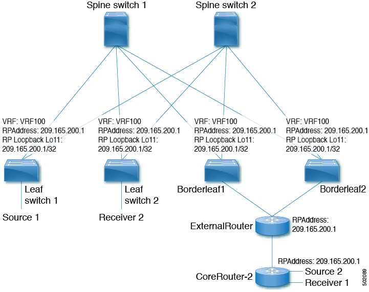
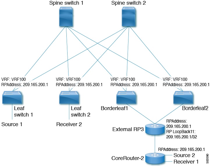
TRM enables seamless integration with existing multicast-enabled networks, supporting external multicast rendezvous points and tenant-aware external connectivity through Layer-3 physical or subinterfaces.

In a data center fabric using TRM, multicast sources and receivers can be located within the data center, in a separate campus network, or reachable externally via the WAN. TRM ensures multicast traffic reaches only interested receivers, even across different sites and tenants, while using underlay multicast replication to optimize bandwidth and resiliency.

Figure 1. VXLAN EVPN TRM
VXLAN EVPN TRM

Tenant routed multicast mixed modes

A tenant routed multicast mixed mode is a VXLAN multicast network feature that:

  • enables TRM-capable and non-TRM-capable edge devices to coexist on the same fabric

  • allows multicast traffic to be partially routed by TRM-capable devices but primarily bridged by legacy devices, and

  • assigns one or more TRM-capable edge devices as gateways to translate multicast traffic between TRM and non-TRM domains.

This mixed mode approach ensures backward compatibility and simplifies migration to newer hardware across the fabric.

A network with both TRM-capable and non-TRM-capable devices uses mixed mode to ensure seamless multicast communication across the fabric.

Figure 2. TRM Layer 2/Layer 3 Mixed Mode

Tenant routed multicast with IPv6 overlay

A tenant routed multicast with IPv6 overlay is a data center multicast architecture that

  • enables multicast traffic for tenant networks by providing IPv6 overlay support in Cisco NX-OS fabric

  • supports multisite deployments using Anycast Border Gateway and Anycast RP, and

  • operates on Cisco Nexus 9300 and 9500 series switches with various overlay configurations.

Beginning with Cisco NX-OS Release 10.2(1), Tenant Routed Multicast (TRM) supports IPv6 in the overlay.

Key supported features include:

  • Multicast IPv4 underlay within fabric.

  • IPv4 underlay in the data center core for multisite.

  • IPv4 overlay only, IPv6 overlay only, or a combination of overlays.

  • Anycast Border Gateway with Border Leaf Role, vPC support on BGW and Leaf, and Virtual MCT on Leaf. Multisite Border Gateway is supported on Cisco Nexus 9300 -FX3, -GX, and GX2 TORs.

  • Anycast RP (internal, external, and RP-everywhere).

  • TRMv6 is supported only on default system routing mode.

  • MLD snooping with VXLAN VLANs with TRM.

  • TRM with IPv6 Overlay is supported on Cisco Nexus 9300 -EX, -FX, - FX2, -FX3, -GX, - GX2 TORs.

The following are not supported by TRM with IPv6 overlay:

  • L2 TRM

  • VXLAN flood mode on L2 VLANs with L3TRM

  • L2-L3 TRM Mixed Mode

  • VXLAN Ingress Replication within a single site

  • IPv6 in the underlay

  • MLD snooping with VXLAN VLANs without TRM

  • PIM6 SVI and MLD snooping configuration on the VLAN

  • MSDP, Bidir and SSM.

Multicast flow path visibility for TRM flows

A multicast flow path visibility for TRM flows is a network diagnostics feature that

  • enables exporting all multicast states in Cisco Nexus 9000 Series switches

  • provides comprehensive traceability of multicast flow paths from source to receiver, and

  • supports both TRM L3 mode and underlay multicast flows starting in Cisco NX-OS Release 10.3(2)F.

Features and limitations of Tenant Routed Multicast

Tenant Routed Multicast (TRM) has these guidelines and limitations:

TRM configuration limitations

  • If VXLAN TRM feature is enabled on a VTEP, it would stop to send IGMP messages to the VXLAN fabric.

  • The Guidelines and Limitations for VXLAN also apply to TRM.

  • If TRM is configured, ISSU is disruptive.

  • TRM supports IPv4 multicast only.

  • TRM requires an IPv4 multicast-based underlay using PIM Any Source Multicast (ASM) which is also known as sparse mode.

  • TRM supports overlay PIM ASM and PIM SSM only. PIM BiDir is not supported in the overlay.

  • Both PIM and ip igmp snooping vxlan must be enabled on the L3 VNI's VLAN in a VXLAN vPC setup.

  • Beginning with Cisco NX-OS Release 10.3(1)F, the Real-time/flex statistics for TRM is supported on Cisco Nexus 9300-X Cloud Scale Switches.

Unsupported features

  • With TRM enabled, SVI as a core link is not supported.

  • TRM with Multi-Site is not supported on Cisco Nexus 9504-R platforms.

RP support

  • RP has to be configured either internal or external to the fabric.

  • The internal RP must be configured on all TRM-enabled VTEPs including the border nodes.

  • The external RP must be external to the border nodes.

  • The RP must be configured within the VRF pointing to the external RP IP address (static RP). This ensures that unicast and multicast routing is enabled to reach the external RP in the given VRF.

  • In a Transit Routing Multicast (TRM) deployment, the RP-on-stick model can sometimes lead to traffic drops if there is flapping on the Protocol Independent Multicast (PIM) enabled interface. Use the ip pim spt-switch-graceful command on the turnaround router that leads to the RP. This command allows for a graceful switch to the Shortest Path Tree (SPT) during flapping, which can minimize traffic drops.

  • TRM supports multiple border nodes. Reachability to an external RP/source via multiple border leaf switches is supported with ECMP and requires symmetric unicast routing.

  • For traffic streams with an internal source and external L3 receiver using an external RP, the external L3 receiver might send PIM S,G join requests to the internal source. Doing so triggers the recreation of S,G on the fabric FHR, and it can take up to 10 minutes for this S,G to be cleared.

Replication support

  • Replication of first packet is supported only on Cisco Nexus 9300 – EX, FX, FX2 family switches.

  • Beginning with Cisco NX-OS Release 10.2(3)F, Replication of first packet is supported on the Cisco Nexus 9300-FX3 platform switches.

FEX support and limitations

  • With Tenant Routed Multicast enabled, FEX is not supported.

Supported platforms

  • Beginning with Cisco NX-OS Release 10.1(2), TRM Multisite with vPC BGW is supported.

  • Beginning with Cisco NX-OS Release 10.2(1q)F, VXLAN TRM is supported on Cisco Nexus N9K-C9332D-GX2B platform switches.

  • Beginning with Cisco NX-OS Release 10.2(3)F, VXLAN TRM is supported on Cisco Nexus 9364D-GX2A, and 9348D-GX2A platform switches.

BGW support

  • TRM supports vPC fabric peering leaf’s as well as vPC/Anycast BGW.

Recommended configuration

  • For Tenant Routed Multicast with eBGP underlay:

    If all leaf switches use the same AS and spine switches use a different AS, enable the maximum-paths command under the address-family ipv4/ipv6 mvpn on the spines.

    This configuration allows spine switches to advertise all available paths to remote peers.

Supported features and limitations of Layer 3 TRM

Layer 3 Tenant Routed Multicast (TRM) has these configuration guidelines and limitations:

  • When configuring TRM VXLAN BGP EVPN, the following platforms are supported:

    • Cisco Nexus 9200, 9332C, 9364C, 9300-EX, and 9300-FX/FX2/FX3/FXP platform switches.

    • Cisco Nexus 9300-GX/GX2 platform switches.

    • Cisco Nexus 9500 platform switches with 9700-EX line cards, 9700-FX line cards, or a combination of both line cards.

  • Layer 3 TRM and VXLAN EVPN Multi-Site are supported on the same physical switch. For more information, see Configure Multi-Site.

  • TRM with vPC border leafs is supported only for Cisco Nexus 9200, 9300-EX, and 9300-FX/FX2/FX3/GX/GX2 platform switches and Cisco Nexus 9500 platform switches with -EX/FXor -R/RX line cards. The advertise-pip and advertise virtual-rmac commands must be enabled on the border leafs to support this functionality. For configuration information, see the "Configuring VIP/PIP" section.

  • To support any Layer 3 source behind one of the vPC peers, whether physical or virtual MCT, a physical link configured as VRF-lite is required between the vPC peers. This setup is necessary to accommodate a receiver located behind the vPC peer, especially if it is the sole receiver in the fabric. This requirement applies to all scenarios where the vPC functions as a BGW, border Leaf, or an internal Leaf.

    On the receiving vPC peer, the VRF-lite link must have a superior reachability metric to the L3 source compared to any other paths (iBGP or eBGP) to be selected as the RPF towards the L3 source. In this configuration, traffic will flow directly to the receiver without traversing the EVPN fabric.

  • Well-known local scope multicast (224.0.0.0/24) is excluded from TRM and is bridged.

  • When an interface NVE is brought down on the border leaf, the internal overlay RP per VRF must be brought down.

  • Beginning with Cisco NX-OS Release 10.3(1)F, TRM support for the new L3VNI mode CLIs are provided on Cisco Nexus 9300-X Cloud Scale switches.

ISSU

  • When upgrading from Cisco NX-OS Release 9.3(3) to Cisco NX-OS Release 9.3(6), if you do not retain configurations of the TRM enabled VRFs from Cisco NX-OS Release 9.3(3), or if you create new VRFs after the upgrade, the auto-generation of ip multicast multipath s-g-hash next-hop-based CLI, when feature ngmvpn is enabled, will not happen. You must enable the CLI manually for each TRM enabled VRF.

TRM Flow Path Visualization support

  • Beginning Cisco NXOS release 10.2(1)F, TRM Flow Path Visualization is supported for flows within a single VXLAN EVPN site.

  • Beginning Cisco NXOS Release 10.3(2)F, TRM Flow Path Visualization support has been extended to below traffic patterns on Cisco Nexus 9000 Series platform switches:

    • TRM Multisite DCI Multicast

    • TRM Multisite DCI IR

    • TRM Data MDT

    • TRM on Virtual MCT vPC

    • TRM using new L3VNI

    • BUM Traffic visibility is not supported.

Layer 3 TRM supported platforms and release

  • Layer 3 TRM is supported for Cisco Nexus 9200, 9300-EX, and 9300-FX/FX2/FX3/FXP and 9300-GX platform switches.

  • Beginning with Cisco NX-OS Release 10.2(3)F, Layer 3 TRM is supported on the Cisco Nexus 9300-GX2 platform switches.

Support for combination of Layer 3 TRM and EVPN Multi-Site

  • Beginning with Cisco NX-OS Release 9.3(7), Cisco Nexus N9K-C9316D-GX, N9K-C9364C-GX, and N9K-X9716D-GX platform switches support the combination of Layer 3 TRM and EVPN Multi-Site.

  • Cisco Nexus 9300-GX platform switches do not support the combination of Layer 3 TRM and EVPN Multi-Site in Cisco NX-OS Release 9.3(5).

  • Beginning with Cisco NX-OS Release 10.2(3)F, the combination of Layer 3 TRM and EVPN Multi-Site is supported on the Cisco Nexus 9300-GX2 platform switches.

Support on Nexus 9800 Series switches

Support on -R/RX linecards

  • Beginning with Cisco NX-OS Release 9.3(3), the Cisco Nexus 9504 and 9508 platform switches with -R/RX line cards support TRM in Layer 3 mode. This feature is supported on IPv4 overlays only. Layer 2 mode and L2/L3 mixed mode are not supported.

    The Cisco Nexus 9504 and 9508 platform switches with -R/RX line cards can function as a border leaf for Layer 3 unicast traffic. For Anycast functionality, the RP can be internal, external, or RP everywhere.

  • TRM Multi-Site functionality is not supported on Cisco Nexus 9504 platform switches with -R/RX line cards.

  • If one or both VTEPs is a Cisco Nexus 9504 or 9508 platform switch with -R/RX line cards, the packet TTL is decremented twice, once for routing to the L3 VNI on the source leaf and once for forwarding from the destination L3 VNI to the destination VLAN on the destination leaf.

Supported features and platforms for Layer 2/Layer 3 TRM (Mixed Mode)

Layer 2/Layer 3 Tenant Routed Multicast (TRM) in Mixed Mode supports the following configurations, platforms, and guidelines:

  • All TRM Layer 2/Layer 3 configured switches must be Anchor DR. This is because in TRM Layer 2/Layer 3, you can have switches configured with TRM Layer 2 mode that co-exist in the same topology. This mode is necessary if non-TRM and Layer 2 TRM mode edge devices (VTEPs) are present in the same topology. 


  • Anchor DR is required to be an RP in the overlay.

  • An extra loopback is required for anchor DRs.

  • Non-TRM and Layer 2 TRM mode edge devices (VTEPs) require an IGMP snooping querier configured per multicast-enabled VLAN. Every non-TRM and Layer 2 TRM mode edge device (VTEP) requires this IGMP snooping querier configuration because in TRM multicast control-packets are not forwarded over VXLAN.

  • The IP address for the IGMP snooping querier can be re-used on non-TRM and Layer 2 TRM mode edge devices (VTEPs).

  • The IP address of the IGMP snooping querier in a VPC domain must be different on each VPC member device.

  • When interface NVE is brought down on the border leaf, the internal overlay RP per VRF should be brought down.

  • The NVE interface must be shut and unshut while configuring the ip multicast overlay-distributed-dr command.

  • Beginning with Cisco NX-OS Release 9.2(1), TRM with vPC border leafs is supported. Advertise-PIP and Advertise Virtual-Rmac need to be enabled on border leafs to support with functionality. For configuring advertise-pip and advertise virtual-rmac, see the "Configuring VIP/PIP" section.

Supported platforms

Anchor DR is supported only on these platforms:

  • Cisco Nexus 9200, 9300-EX, and 9300-FX/FX2 platform switches

  • Cisco Nexus 9500 platform switches with 9700-EX line cards, 9700-FX line cards, or a combination of both line cards

  • Beginning with Cisco NX-OS Release 10.2(3)F, Anchor DR is supported on the Cisco Nexus 9300-FX3 platform switches.

Unsupported features and platforms

  • Layer 2/Layer 3 Tenant Routed Multicast (TRM) is not supported on Cisco Nexus 9300-FX3/GX/GX2 platform switches.

Supported rendezvous point options by TRM mode

With TRM enabled Internal and External RP is supported. These tables provide information about which TRM modes support internal and external rendezvous point (RP) options, along with the minimum supported NX-OS release for each combination. This information helps network designers and administrators determine the appropriate TRM modes and software versions needed for specific RP deployments.

Table 1. TRM RP support

Mode

RP Internal

RP External

PIM-Based RP Everywhere

TRM L2 Mode

N/A

N/A

N/A

TRM L3 Mode

7.0(3)I7(1), 9.2(x)

7.0(3)I7(4), 9.2(3)

Supported in 7.0(3)I7(x) releases starting from 7.0(3)I7(5)

Not supported in 9.2(x)

Supported in NX-OS releases beginning with 9.3(1) for the following Nexus 9000 switches:

  • Cisco Nexus 9200 Series switches

  • Cisco Nexus 9364C platform switches

  • Cisco Nexus 9300-EX/FX/FX2 platform switches (excluding the Cisco Nexus 9300-FXP platform switch)

Supported for Cisco Nexus 9300-FX3 platform switches beginning with Cisco NX-OS Release 9.3(5)

TRM L2L3 Mode

7.0(3)I7(1), 9.2(x)

N/A

N/A

Options for rendezvous points in TRM deployments

For Tenant Routed Multicast, these rendezvous point options are supported:

Configure a rendezvous point inside the VXLAN fabric

Configure the loopback interface and related parameters for TRM VRFs on all VTEPs. This ensures multicast traffic is managed correctly and efficiently throughout the fabric. The loopback address must be reachable and advertised in EVPN.

Follow these steps to configure the rendezvous point inside the VXLAN fabric:

Before you begin

  • Verify that all devices (VTEPs) support TRM VRFs.

  • Ensure network connectivity so the loopback address is reachable in EVPN.

  • Plan and reserve the loopback IP address for the RP.

Procedure


Step 1

Enter global configuration mode.

Example:

switch# configure terminal

Step 2

Configure the loopback interface for use with multicast RP on all TRM-enabled nodes.

Example:

switch(config)# interface loopback 11

Step 3

Assign the loopback interface to the correct VRF.

Example:

switch(config-if)# vrf member vrf100

Step 4

Specify the IP address for the loopback interface.

Example:

switch(config-if)# ip address 209.165.200.1/32

Step 5

Enable PIM sparse-mode on the loopback interface.

Example:

switch(config-if)# ip pim sparse-mode

Step 6

Create the VXLAN tenant VRF if it does not already exist.

Example:

switch(config-if)# vrf context vrf100

Step 7

Configure the RP address and group-list for multicast.

Example:

switch(config-vrf# ip pim rp-address 209.165.200.1 group-list 224.0.0.0/4

Use the same RP IP address for all edge devices (VTEPs) to enable a fully distributed RP.


The rendezvous point for multicast is configured and distributed across all VTEPs in the VXLAN fabric, allowing for efficient multicast routing and group communication.

Configure an external rendezvous point

Configure the external rendezvous point (RP) IP address within the TRM VRFs on all devices (VTEP). In addition, ensure reachability of the external RP within the VRF via the border node.

Follow these steps to configure an external rendezvous point:

Before you begin

Ensure TRM is enabled.

  • Identify the RP IP address to use.

  • Confirm all relevant VTEP and border node devices are reachable.

  • Ensure only one routing path (non-ECMP) is active between the TRM fabric and the external RP via a single border leaf.

Procedure


Step 1

Enter configuration mode.

Example:

switch# configure terminal

Step 2

Enter the target TRM VRF context.

Example:

switch(config)# vrf context vrf100

Step 3

Configure the multicast RP address for the VRF.

Example:

switch(config-vrf)# ip pim rp-address 209.165.200.1 group-list 224.0.0.0/4

Use the same RP IP address on all edge devices (VTEPs) for a distributed RP setup.


The external rendezvous point is configured for multicast in the TRM fabric. All devices in the specified VRFs use the designated RP, and multicast routing traverses a single, controlled border node as intended.

RP Everywhere with PIM Anycast solution

RP Everywhere with PIM Anycast provides these features and benefits:

  • Enables efficient Rendezvous Point (RP) redundancy and load sharing for multicast routing.

  • Supports seamless failover using Anycast addresses, minimizing service interruptions.

  • Allows multiple RPs to share a single logical Anycast address for improved scalability.

  • Provides automatic failover between RPs, enhancing network resilience.

  • Simplifies configuration and ongoing maintenance for multicast deployments.

  • Maintains seamless multicast signaling across the network.

For information about configuring RP Everywhere with PIM Anycast, see:

Configure a TRM leaf node for RP Everywhere with PIM Anycast

Perform this configuration on each VXLAN VTEP device that will participate as a distributed RP in an Anycast RP model for multicast routing.

Before you begin

  • Ensure device access with the necessary privileges.

  • Determine the loopback interface number, VRF name, RP IP address, and multicast group range to be used.

  • Verify that all edge devices (VTEPs) share the same RP IP address.

Procedure

Step 1

Enter configuration mode.

Example:
switch# configure terminal

Step 2

Create and configure a loopback interface for RP functionality on each VXLAN VTEP.

Example:
switch(config)# interface loopback 11

Assign the desired loopback interface number.

Step 3

Assign the loopback interface to the relevant VRF.

Example:
switch(config-if)# vrf member vrf100

Step 4

Set an IP address for the loopback interface.

Example:
switch(config-if)# ip address 209.165.200.1/32

Step 5

Enable PIM sparse mode on the loopback interface.

Example:
switch(config-if)# ip pim sparse-mode

Step 6

Create the VXLAN tenant VRF context.

Example:
switch(config-if)# vrf context vrf100

Step 7

Configure the RP address and group list for PIM, specifying the RP IP address and multicast group range. ip pim rp-address ip-address-of-router group-list group-range-prefix

Example:
switch(config-vrf# ip pim rp-address 209.165.200.1 group-list 224.0.0.0/4

Ensure that the same RP IP address and group range are configured on all VXLAN VTEPs to enable a fully distributed RP.


The TRM leaf node is configured as a distributed Rendezvous Point (RP) for RP Everywhere, supporting PIM Anycast within the specified VXLAN tenant.

Configure a TRM border leaf node for RP Everywhere with PIM Anycast

Configure a TRM border leaf node to enable distributed RP functionality for multicast routing with PIM Anycast in a VXLAN-EVPN fabric.

Follow these steps to configure the TRM border leaf node:

Before you begin

  • Ensure you have the required IP addresses and VRF names.

  • Confirm administrative CLI access to the switch.

  • Verify VXLAN-EVPN mode is enabled.

Procedure

Step 1

Enter configuration mode.

Example:
switch# configure terminal

Step 2

Configure VXLAN VTEP as TRM border leaf node.

Example:
switch(config)# ip pim evpn-border-leaf

Step 3

Create loopback interfaces for TRM and RP Anycast.

Example:
switch(config)# interface loopback 11
switch(config)# interface loopback 12
switch(config-if)#

Step 4

Assign VRF to each loopback interface.

Example:
!For TRM
switch(config-if)# vrf member vrf100
!For RP loopback
switch(config-if)# vrf member vxlan100

Step 5

Specify IP addresses for loopback interfaces.

Example:
!For TRM
switch(config-if)# ip address 209.165.200.1/32
!For RP loopback
switch(config-if)# ip address 209.165.200.11/32

Step 6

Enable sparse-mode PIM on both loopback interfaces.

Example:
switch(config-if)# ip pim sparse-mode

Step 7

Create a VXLAN tenant VRF.

Example:
switch(config-if)# vrf context vrf100

Step 8

Configure the PIM RP address and group list.

Example:
switch(config-vrf)# ip pim rp-address 209.165.200.1 group-list 224.0.0.0/4

Ensure that the same RP IP address and group range are configured on all VXLAN VTEPs to enable a fully distributed RP.

Step 9

Configure PIM Anycast RP set with required addresses.

Example:
switch(config-vrf)# ip pim anycast-rp 209.165.200.1 209.165.200.11
switch(config-vrf)# ip pim anycast-rp 209.165.200.1 209.165.200.12
switch(config-vrf)# ip pim anycast-rp 209.165.200.1 209.165.200.13
switch(config-vrf)# ip pim anycast-rp 209.165.200.1 209.165.200.14

The TRM border leaf node now serves as a distributed RP with PIM Anycast, ready to support multicast traffic in the VXLAN-EVPN fabric.

Configure an external router for RP Everywhere with PIM Anycast

Configure an external router to act as a Rendezvous Point (RP) for multicast traffic, using Protocol Independent Multicast (PIM) Anycast RP for redundancy and scalability.

Follow these steps to configure the external router for RP Everywhere with PIM Anycast:

Before you begin

  • Ensure you have administrative access to the router.

  • Identify the loopback interfaces and VRF names to be used.

  • Gather the required IP addresses for the PIM Anycast RP set.

Procedure

Step 1

Enter configuration mode.

Example:
switch# configure terminal

Step 2

Create the first loopback interface.

Example:
switch(config)# interface loopback 11

Step 3

Assign the loopback interface to a VRF.

Example:
switch(config-if)# vrf member vfr100

Step 4

Assign an IP address to the loopback interface.

Example:
switch(config-if)# ip address 209.165.200.1/32

Step 5

Enable PIM sparse mode on the loopback interface.

Example:
switch(config-if)# ip pim sparse-mode

Step 6

Create a second loopback interface for additional Anycast RP.

Example:
switch(config)# interface loopback 12
  1. Repeat Steps 3–5 for this interface with its respective VRF and IP

    Example:
    switch(config-if)# vrf member vrf100
    switch(config-if)# ip address 209.165.200.13/32
    switch(config-if)# ip pim sparse-mode

Step 7

Create the VXLAN tenant VRF if not already created.

Example:
switch(config-if)# vrf context vrf100

Step 8

Configure the PIM RP address and group-list.

Example:
switch(config-vrf)# ip pim rp-address 209.165.200.1 group-list 224.0.0.0/4

Ensure that the same RP IP address and group range are configured on all VXLAN VTEPs to enable a fully distributed RP.

Step 9

Configure PIM Anycast RP set with required addresses. ip pim anycast-rp anycast-rp-address address-of-rp

Example:
switch(config-vrf)# ip pim anycast-rp 209.165.200.1 209.165.200.11
switch(config-vrf)# ip pim anycast-rp 209.165.200.1 209.165.200.12
switch(config-vrf)# ip pim anycast-rp 209.165.200.1 209.165.200.13
switch(config-vrf)# ip pim anycast-rp 209.165.200.1 209.165.200.14

The router is configured as a PIM Anycast Rendezvous Point, providing a resilient multicast RP for the network.

Features of RP Everywhere with MSDP peering solutions

RP Everywhere with MSDP peering is a multicast routing solution that offers the following features:

  • Each router can act as a Rendezvous Point (RP) for its own domain, improving local multicast source management.

  • Multicast Source Discovery Protocol (MSDP) enables sharing of multicast source information between RPs in different domains, allowing seamless inter-domain multicast communication.

  • The solution provides redundancy, scalability, and resiliency for multicast services across network segments.

This approach is beneficial for large-scale multicast deployments where high availability and inter-domain source discovery are required.

For information about configuring RP Everywhere with MSDP Peering, see:

Figure 3. RP Everywhere configuration with MSDP RP solution
RP Everywhere configuration with MSDP RP solution

Configure a TRM leaf node for RP Everywhere with MSDP peering

Configure a TRM leaf node to support RP Everywhere architecture using MSDP peering, allowing distributed Rendezvous Point (RP) functionality for multicast routing in a VXLAN environment.

Follow these steps to configure a TRM leaf node for RP Everywhere with MSDP peering:

Before you begin

  • Confirm you are logged in with administrative privileges.

  • Verify VXLAN and multicast routing features are enabled.

  • Gather the required IP addresses and VRF names for configuration.

Procedure

Step 1

Enter configuration mode.

Example:
switch# configure terminal

Step 2

Configure the loopback interface on all VXLAN VTEP devices.

Example:
switch(config)# interface loopback 11

Step 3

Assign the loopback interface to the appropriate VRF.

Example:
switch(config-if)# vrf member vrf100

Step 4

Specify the IP address for the loopback interface.

Example:
switch(config-if)# ip address 209.165.200.1/32

Specify IP address.

Step 5

Enable PIM sparse mode on the loopback interface.

Example:
switch(config-if)# ip pim sparse-mode

Step 6

Create the VXLAN tenant VRF context.

Example:
switch(config-if)# vrf context vrf100

Step 7

Configure the RP address and multicast group range for MSDP peering.

Example:
switch(config-vrf# ip pim rp-address 209.165.200.1 group-list 224.0.0.0/4

Ensure that the same RP IP address and group range are configured on all VXLAN VTEPs to enable a fully distributed RP.


The TRM leaf node is now configured for RP Everywhere with MSDP peering, enabling distributed multicast routing across all VXLAN VTEP edge devices.

Configure a TRM border leaf node for RP Everywhere with MSDP peering

Configure a TRM border leaf node to function as an Anycast Rendezvous Point (RP) with MSDP peering for multicast source discovery in a VXLAN EVPN fabric

Follow these steps to configure the TRM border leaf node:

Before you begin

  • Identify the loopback interfaces and IP addresses for the Anycast RP.

  • Determine the VRF name used for multicast routing.

  • Ensure your device supports PIM and MSDP features.

Procedure

Step 1

Enter configuration mode.

Example:
switch# configure terminal

Step 2

Enable the MSDP feature.

Example:
switch(config)# feature msdp

Step 3

Configure VXLAN VTEP as TRM border leaf node,

Example:
switch(config)# ip pim evpn-border-leaf

Step 4

Create the first loopback interface for the primary Anycast RP address:

  1. Assign the VRF membership.

    Example:
    switch(config)# interface loopback 11
    switch(config-if)# vrf member vrf100
  2. Configure the Anycast RP IP address.

    Example:
    switch(config-if)# ip address 209.165.200.1/32
  3. Enable PIM sparse mode.

    Example:
    switch(config-if)# ip pim sparse-mode

Step 5

Create the second loopback interface for Anycast RP redundancy

  1. Assign the VRF membership.

    Example:
    switch(config)# interface loopback 12
    switch(config-if)# vrf member vrf100
  2. Configure the Anycast RP IP address.

    Example:
    switch(config-if)# ip address 209.165.200.11/32
  3. Enable PIM sparse mode.

    Example:
    switch(config-if)# ip pim sparse-mode

Step 6

Create the tenant VRF context for multicast:

Example:
switch(config-if)# vrf context vrf100

Step 7

Configure the RP address and group list for PIM in the VRF.

Example:
switch(config-vrf)# ip pim rp-address 209.165.200.1 group-list 224.0.0.0/4

Ensure that the same RP IP address and group range are configured on all VXLAN VTEPs to enable a fully distributed RP.

Step 8

Configure PIM Anycast RP set and assign all participating RP addresses

Example:
switch(config-vrf)# ip pim anycast-rp 209.165.200.1 209.165.200.11

Configure PIM Anycast RP set.

Step 9

Configure MSDP originator ID and peer under the VRF:

  1. Assign the originator loopback.

    Example:
    switch(config-vrf)# ip pim anycast-rp 209.165.200.1 209.165.200.12
    switch(config-vrf)# ip msdp originator-id loopback12
  2. Define the MSDP peer and source loopback

    Example:
    loopback
    switch(config-vrf)# ip msdp peer 209.165.201.11 connect-source loopback12

The TRM border leaf node is enabled as an Anycast RP, participating in MSDP peering for distributed multicast routing in the fabric.

Configure an external router for RP Everywhere with MSDP peering

Configure an external router to support Rendezvous Point (RP) Everywhere multicast operation using MSDP peering.

Procedure

Step 1

Enter configuration mode.

Example:
switch# configure terminal

Step 2

Enable the MSDP feature.

Example:
switch(config)# feature msdp

Step 3

Configure the first loopback interface on all VXLAN VTEP devices.

Example:
switch(config)# interface loopback 11
switch(config-if)# vrf member vrf100
switch(config-if)# ip address 209.165.201.1/32
switch(config-if)# ip pim sparse-mode

Step 4

Configure the PIM Anycast set RP loopback interface.

Example:
switch(config)# interface loopback 12
switch(config-if)# vrf member vrf100
switch(config-if)# ip address 209.165.201.11/32
switch(config-if)# ip pim sparse-mode

Configure the PIM Anycast set RP loopback interface.

Step 5

Create the VXLAN tenant VRF.

Example:
switch(config-if)# vrf context vrf100

Step 6

Configure the Rendezvous Point (RP) address and multicast group range.

Example:
switch(config-vrf)# ip pim rp-address 209.165.201.1 group-list 224.0.0.0/4

Ensure that the same RP IP address and group range are configured on all VXLAN VTEPs to enable a fully distributed RP.

Step 7

Set the MSDP originator ID to the Anycast RP loopback

Example:
switch(config-vrf)# ip msdp originator-id loopback12

Step 8

Establish MSDP peering with each TRM border node

Example:
switch(config-vrf)# ip msdp peer 209.165.200.11 connect-source loopback12

Configure MSDP peering between external RP router and all TRM border nodes.


The external router is now configured as an RP and MSDP peer, supporting distributed multicast operation for VXLAN in the network.

Configure Layer 3 Tenant Routed Multicast

This procedure enables the Tenant Routed Multicast (TRM) feature. TRM operates primarily in the Layer 3 forwarding mode for IP multicast by using BGP MVPN signaling. TRM in Layer 3 mode is the main feature and the only requirement for TRM enabled VXLAN BGP EVPN fabrics. If non-TRM capable edge devices (VTEPs) are present, the Layer 2/Layer 3 mode and Layer 2 mode have to be considered for interop.

To forward multicast between senders and receivers on the Layer 3 cloud and the VXLAN fabric on TRM vPC border leafs, the VIP/PIP configuration must be enabled. For more information, see Configuring VIP/PIP.


Note


TRM follows an always-route approach and hence decrements the Time to Live (TTL) of the transported IP multicast traffic.


Follow these steps to configure Layer 3 Tenant Routed Multicast:

Before you begin

  • Ensure VXLAN EVPN (feature nv overlay, nv overlay evpn) is enabled.

  • Confirm the rendezvous point (RP) is configured.

  • Enable PIM v4/v6 if TRM v4/v6 is needed.

Procedure


Step 1

Enable the Next-Generation Multicast VPN (ngMVPN) control plane.

Example:

switch# configure terminal
switch(config)# feature ngmvpn

New address family commands become available in BGP.

Note


The no feature ngmvpn command will not remove MVPN configuration under BGP.

You will get a syslog message when you enable this command. The message informs you that ip multicast multipath s-g-hash next-hop-based is the recommended multipath hashing algorithm and you need enable it for the TRM enabled VRFs.

The auto-generation of ip multicast multipath s-g-hash next-hop-based command does not happen after you enable the feature ngmvpn command. You need to configure ip multicast multipath s-g-hash next-hop-based as part of the VRF configuration.

Step 2

Configure IGMP snooping for VXLAN VLANs.

Example:

switch(config)# ip igmp snooping vxlan

Step 3

Configure the NVE (Network Virtualization Edge) interface and associate the Layer 3 VNI with the VRF.

Example:

switch(config)# interface nve 1
switch(config-if-nve)# member vni 200100 associate-vrf
switch(config-if-nve-vni)# mcast-group 225.3.3.3

The range of vni-range is from 1 to 16,777,214.

Builds the default multicast distribution tree for the VRF VNI (Layer 3 VNI).

The multicast group is used in the underlay (core) for all multicast routing within the associated Layer 3 VNI (VRF).

Note


We recommend that underlay multicast groups for Layer 2 VNI, default MDT, and data MDT not be shared. Use separate, non-overlapping groups.

Step 4

Set up BGP and enable multicast VPN for the peer

Example:

switch(config)# router bgp 100
switch(config-router)# neighbor 1.1.1.1
switch(config-router-neighbor)# address-family ipv4 mvpn
switch(config-router-neighbor-af)# send-community extended

Enables ngMVPN for address family signalization. The send community extended command ensures that extended communities are exchanged for this address family.

Step 5

Configure the tenant VRF context, VNI, and enable TRM.

Example:

switch(config-router)# vrf context vrf100
switch(config-router)# vni 500001 l3
switch(config-router)# mvpn vri 100 
switch(config-router)# mdt v4 vxlan

Beginning with Cisco NX-OS Release 10.3(1)F, the L3 keyword is provided to indicate that the new L3VNI configuration is enabled.

Run the mvpn vri id<id> command under router bgp <as-number> submode. The vri id range is from 1 to 65535.

Note

 
  • This command is mandatory on vPC leaf nodes, and value has to be same across vPC pair and unique in TRM domain. Also the value must not collide with any site-id value.

  • This command is required on BGWs if site-id value is greater than 2 bytes, and value has to be same across all same site BGWs and unique in TRM domain. Also the value must not collide with any site-id value.

The TRM v4/v6 is enabled by default.

The no mdt [ v4 | v6 ] vxlan command disables the TRM v4/v6 on the specified VRF.

Run this command under the sub-mode of new L3VNI config.

Note

 
This command is applicable only to VRFs configured with new-L3VNI.

Step 6

Enable recommended multipath hashing for TRM-enabled VRFs.

Example:

switch(config-vrf)# ip multicast multipath s-g-hash next-hop-based

Configures multicast multipath and initiates S, G, nexthop hashing (rather than the default of S/RP, G-based hashing) to select the RPF interface.

Step 7

Specify the rendezvous point (RP) address for multicast traffic.

Example:

switch(config-vrf)# ip pim rp-address 209.165.201.1 group-list 226.0.0.0/8

Ensure that the same RP IP address and group range are configured on all VXLAN VTEPs to enable a fully distributed RP.

For overlay RP placement options, see the Options for rendezvous points in TRM deployments section.

Step 8

Configure SVI for Layer 2 and Layer 3 VNIs, assign VRF membership, and enable PIM as required.

Example:

switch(config)# interface vlan11
switch(config-if)# no shutdown
switch(config-if)# vrf member vrf100
switch(config-if)# ip address 11.1.1.1/24
switch(config-if)# ip pim sparse-mode
switch(config-if)# ip pim neighbor-policy route-map1 !if preventing PIM neighborship on L2VNI SVI
switch(config-if)# fabric forwarding mode anycast-gateway !as needed
switch(config-if)# ip forward !for L3VNI SVI

Configures the first-hop gateway (distributed anycast gateway for the Layer 2 VNI. No router PIM peering must ever happen with this interface.

Creates an IP PIM neighbor policy with a suitable route-map to deny any IPv4 addresses, preventing PIM from establishing PIM neighborship on the L2VNI SVI.

Note


Do not use Distributed Anycast Gateway for PIM Peerings.

Step 9

Configure the BGP address family for unicast and set the auto route-target for multicast VPN.

Example:

switch(config-vrf)# address-family ipv4 unicast
switch(config-vrf-af-ipv4)# route-target both auto mvpn
switch(config)# ip multicast overlay-spt-only

Defines the BGP route target that is added as an extended community attribute to the customer multicast (C_Multicast) routes (ngMVPN route type 6 and 7).

Auto route targets are constructed by the 2-byte Autonomous System Number (ASN) and Layer 3 VNI.

Gratuitously originate (S,A) route when the source is locally connected. The ip multicast overlay-spt-only command is enabled by default on all MVPN-enabled Cisco Nexus 9000 Series switches (typically leaf node).


Layer 3 Tenant Routed Multicast is enabled, providing IP multicast forwarding for tenants over the VXLAN BGP EVPN fabric.

Configure TRM on the VXLAN EVPN spine

This procedure enables Tenant Routed Multicast (TRM) on a VXLAN EVPN spine switch.

Follow these steps to configure TRM on the VXLAN EVPN spine:

Before you begin

  • Confirm that the VXLAN BGP EVPN spine configuration is complete. For more information see Configure iBGP for EVPN on the spine.

  • Ensure you know your BGP autonomous system numbers and neighbor IP addresses.

Procedure


Step 1

Enter configuration mode.

Example:

switch# configure terminal

Step 2

Create a route-map to retain the next-hop for EVPN routes.

Example:

switch(config)# route-map permitall permit 10

Note


The route-map keeps the next-hop unchanged for EVPN routes

  • Required for eBGP

  • Options for iBGP

Step 3

Retain the next-hop attribute in the route-map.

Example:

switch(config-route-map)# set ip next-hop unchanged
switch(config-route-map)# exit
switch(config)#

Note


The route-map keeps the next-hop unchanged for EVPN routes

  • Required for eBGP

  • Options for iBGP

Step 4

Enter BGP router configuration mode using your AS number.

Example:

switch(config)# router bgp 65002

Specify BGP.

Step 5

Configure the address family IPv4 MVPN under the BGP.

Example:

switch(config-router)# address-family ipv4 mvpn

Step 6

Configure retain route-target all under address-family IPv4 MVPN [global].

Example:

switch(config-router-af)# retain route-target all

Note


Required for eBGP. Allows the spine to retain and advertise all MVPN routes when there are no local VNIs configured with matching import route targets.

Step 7

Configure your BGP multicast VPN neighbor.

Example:

switch(config-router-af)# neighbor 100.100.100.1 

Step 8

Under the neighbor’s IPv4 MVPN address-family, apply TRM-specific settings:

Example:

switch(config-router-neighbor)# address-family ipv4 mvpn
  1. If using eBGP, enter:

    Example:

    switch(config-router-neighbor-af)# disable-peer-as-check
    switch(config-router-neighbor-af)# rewrite-rt-asn
    switch(config-router-neighbor-af)# send-community extended
    switch(config-router-neighbor-af)# route-map permitall out

    Configure disable-peer-as-check parameter on the spine for eBGP when all leafs are using the same AS but the spines have a different AS than leafs.

    The rewrite-rt-asn command is required if the route target auto feature is being used to configure EVPN route targets.

  2. If using iBGP with route reflectors, enter:

    Example:

    switch(config-router-neighbor-af)# route-reflector-client

Step 9

Exit configuration and save your changes.


TRM is enabled on the VXLAN EVPN spine, supporting multicast routing for tenant networks.

Configure TRM in Layer 2 and Layer 3 mixed mode

This procedure enables the Tenant Routed Multicast (TRM) feature. This enables both Layer 2 and Layer 3 multicast BGP signaling. This mode is only necessary if non-TRM edge devices (VTEPs) are present in the Cisco Nexus 9000 Series switches (1st generation) . Only the Cisco Nexus 9000-EX and 9000-FX switches can do Layer 2/Layer 3 mode (Anchor-DR).

To forward multicast between senders and receivers on the Layer 3 cloud and the VXLAN fabric on TRM vPC border leafs, the VIP/PIP configuration must be enabled. For more information, see Configuring VIP/PIP.

All Cisco Nexus 9300-EX and 9300-FX platform switches must be in Layer 2/Layer 3 mode.

Follow these steps to configure Tenant Routed Multicast (TRM) in Layer 2/Layer 3 mixed mode:

Before you begin

  • Ensure VXLAN EVPN is configured.

  • Ensure the rendezvous point (RP) is configured for multicast.

Procedure


Step 1

Enter configuration mode.

Example:

switch# configure terminal

Step 2

Enable ngMVPN and advertise EVPN multicast.feature ngmvpn

Example:

switch(config)# feature ngmvpn
switch(config)# advertise evpn multicast

Note


The no feature ngmvpn command does not remove MVPN configuration under BGP.

Step 3

Enable IGMP snooping for VXLAN VLANs.

Example:

switch(config)# ip igmp snooping vxlan

Step 4

Enable multicast overlay SPT-only and distributed anchor DR.

Example:

switch(config)# ip multicast overlay-spt-only
switch(config)# ip multicast overlay-distributed-dr

Gratuitously originate (S,A) route when source is locally connected. The ip multicast overlay-spt-only command is enabled by default on all MVPN-enabled Cisco Nexus 9000 Series switches (typically leaf nodes).

Note


You must shut and unshut the NVE interface after configuring ip multicast overlay-distributed-dr .

Step 5

Configure the NVE interface, associate Layer 3 VNIs, and assign multicast groups.

Example:

switch(config)# interface nve 1
switch(config-if-nve)# member vni 200100 associate-vrf
switch(config-if-nve-vni)# mcast-group 225.3.3.3

The range of vni-range is from 1 to 16,777,214.

Step 6

Set up loopback interface on all anchor DR devices, and configure OSPF and PIM.

Example:

switch(config-if-nve)# interface loopback 10
switch(config-if)# ip address 100.100.1.1/32
switch(config-if)# ip router ospf 100 area 0.0.0.0
switch(config-if)# ip pim sparse-mode

The IP address must be the same on all distributed anchor DRs.

Step 7

Configure multicast routing to override the source-interface on every TRM-enabled VTEP (Anchor DR).

Example:

switch(config-if)# interface nve1
switch(config-if-nve)# mcast-routing override source-interface loopback 10

The loopback10 variable must be configured on every TRM-enabled VTEP (Anchor DR) in the underlay with the same IP address. This loopback and the respective override command are needed to serve TRM VTEPs in co-existence with non-TRM VTEPs.

Step 8

Configure BGP for multicast VPN and send extended communities and set route-targets.

Example:

switch(config)# router bgp 100
switch(config-router)# neighbor 1.1.1.1
switch(config-router-neighbor)# address-family ipv4 mvpn
switch(config-router-neighbor-af)# send-community extended
switch(config-vrf-af-ipv4)# route-target both auto mvpn

Step 9

Configure Layer 2/Layer 3 VNI VLAN interfaces with IP, PIM, and anycast gateway settings.

Example:

switch(config)# interface vlan11  ! Layer 2 VNI
switch(config-if)# vrf member vrf100
switch(config-if)# ip address 11.1.1.1/24
switch(config-if)# ip pim sparse-mode
switch(config-if)# fabric forwarding mode anycast-gateway
switch(config-if)# ip pim neighbor-policy route-map1
switch(config-if)# exit
switch(config)# interface vlan100   !Layer 3 VNI
switch(config-if)# vrf member vrf100
switch(config-if)# ip forward
switch(config-if)# ip pim sparse-mode
switch(config-if)# exit
switch(config)# vrf context vrf100
switch(config-vrf)# ip pim rp-address 209.165.201.1 group-list 226.0.0.0/8
switch(config-vrf)# address-family ipv4 unicast

For overlay RP placement options, see the Options for rendezvous points in TRM deployments.

To prevent PIM neighborship on the L2VNI SVI, create an IP PIM neighbor policy with a suitable route map to deny IPv4 addresses.

Ensure that the same RP IP address and group range are configured on all VXLAN VTEPs to enable a fully distributed RP.


Tenant Routed Multicast is enabled in Layer 2/Layer 3 mixed mode, allowing multicast traffic forwarding between senders and receivers across the fabric and external Layer 3 networks.

Configure Layer 2 Tenant Routed Multicast

Before you begin

VXLAN EVPN must be configured.

TRM allows multicast traffic optimization by signaling Layer 2 multicast routes. This procedure activates TRM features and configures IGMP snooping querier settings on required switches.

Follow these steps to configure Layer 2 Tenant Routed Multicast:

Before you begin

  • VXLAN EVPN must be configured.

  • You must configure IGMP snooping querier per multicast-enabled VXLAN VLAN on all Layer-2 TRM leaf switches.

Procedure


Step 1

Enter configuration mode.

Example:

switch# configure terminal

Step 2

Enable the EVPN/MVPN feature.

Example:

switch(config)# feature ngmvpn

Note


Disabling this feature with the no feature ngmvpn command does not remove existing MVPN configurations under BGP.

Step 3

Advertise Layer 2 multicast capability for EVPN.

Example:

switch(config)# advertise evpn multicast

Step 4

Enable IGMP snooping for VXLANs.

Example:

switch(config)# ip igmp snooping vxlan

Step 5

Enter VLAN configuration mode for each multicast-enabled VXLAN VLAN.

Example:

switch(config)# vlan configuration 101

Step 6

Configure the IGMP snooping querier by specifying its IP address for each relevant VLAN.

Example:

switch(config-vlan-config)# ip igmp snooping querier 2.2.2.2

TRM is enabled with Layer 2 multicast and IGMP snooping querier configured, ensuring proper multicast routing and signaling within the VXLAN EVPN fabric.

Configure TRM with vPC support

You can onfigure TRM Multisite with vPC support on Cisco NX-OS. Beginning with Cisco NX-OS Release 10.1(2), TRM Multisite with vPC BGW is supported.

Follow these steps to configure TRM with vPC support:

Procedure


Step 1

Enter global configuration mode.

Example:

switch# configure terminal 

Step 2

Enable required features:

Example:

switch(config)# feature vpc
switch(config)# feature interface-vlan
switch(config)# feature lacp
switch(config)# feature pim
switch(config)# feature ospf

Step 3

Configure PIM RP address for the multicast group range:

Example:

switch(config)# ip pim rp-address 100.100.100.1 group-list 224.0.0/4

Step 4

Configure the vPC domain and basic vPC parameters.

Example:

switch(config)# vpc domain 1
switch(config-vpc-domain)# peer switch
switch(config-vpc-domain)# peer gateway
switch(config-vpc-domain)# peer-keepalive destination 172.28.230.85

There is no default for vPC domain. The range is from 1 to 1000.

To enable Layer 3 forwarding for packets destined to the gateway MAC address of the virtual port channel (vPC), use the peer-gateway command.

The peer-keepalive destination ipaddress command configures the IPv4 address for the remote end of the vPC peer-keepalive link.

Note


The system does not form the vPC peer link until you configure a vPC peer-keepalive link.

The management ports and VRF are the defaults.

Note


We recommend that you configure a separate VRF and use a Layer 3 port from each vPC peer device in that VRF for the vPC peer-keepalive link.

For more information about creating and configuring VRFs, see the Cisco Nexus 9000 NX-OS Series Unicast Routing Config Guide, 9.3(x).

Step 5

(Optional) Set the delay restore timer for SVIs as needed.

Example:

switch(config-vpc-domain)# delay restore interface-vlan 45

We recommend tuning this value when the SVI/VNI scale is high. For example, when the SCI count is 1000, we recommend that you set the delay restore for interface-vlan to 45 seconds.

Step 6

Enable ARP and IPv6 ND synchronization for faster recovery.

Example:

switch(config-vpc-domain)# ip arp synchronize
switch(config-vpc-domain)# ipv6 nd synchronize

Step 7

Create the vPC peer-link port-channel interface and add member interfaces.

Example:

switch(config)# interface port-channel 1
                        switch(config)# switchport
                        switch(config)# switchport mode trunk
                        switch(config)# switchport trunk allowed vlan 1,10,100-200
                        switch(config)# mtu 9216
                        switch(config)# vpc peer-link
                        switch(config)# no shut
                        
                        switch(config)# interface Ethernet 1/1, 1/21
                        switch(config)# switchport
                        switch(config)# mtu 9216
                        switch(config)# channel-group 1 mode active
                        switch(config)# no shutdown
                    

Step 8

Define the infra-VLAN and create the required VLAN.

Example:

switch(config)# system nve infra-vlans 10
switch(config)# vlan 10

Step 9

Configure the SVI for the infra-VLAN and enable underlay routing.

Example:

switch(config)# interface vlan 10
switch(config)# ip address 10.10.10.1/30
switch(config)# ip router ospf process UNDERLAY area 0
switch(config)# ip pim sparse-mode
switch(config)# no ip redirects
switch(config)# mtu 9216
switch(config)# no shutdown

Configure TRM with vPC support on Cisco Nexus 9504-R and 9508-R switches

Use this task when deploying VXLAN TRM in a vPC topology on Cisco Nexus 9504-R and 9508-R switches equipped with -R line cards.

Follow these steps to configure TRM with vPC support:

Before you begin

  • Ensure you have CLI access to a Cisco Nexus 9504-R or 9508-R switch with -R line cards.

  • Back up your running configuration.

Procedure


Step 1

Enter global configuration mode.

Example:

switch# configure terminal 

Step 2

Enable the following features: vPC, interface VLAN, LACP, PIM, and OSPF.

Example:

switch(config)# feature vpc
switch(config)# feature interface-vlan
switch(config)# feature lacp
switch(config)# feature pim
switch(config)# feature ospf

Step 3

Define the PIM RP address for the multicast group range.

Example:

switch(config)# ip pim rp-address 100.100.100.1 group-list 224.0.0/4

Step 4

(Optional) Set the delay restore timer for SVIs as needed.

Example:

switch(config-vpc-domain)# delay restore interface-vlan 45

Enables the delay restore timer for SVIs. We recommend tuning this value when the SVI/VNI scale is high. For example, when the SCI count is 1000, we recommend that you set the delay restore for interface-vlan to 45 seconds.

Step 5

Carve TCAM regions for TRM and VXLAN as required for N9K-X9636C-RX line cards only and reload the switch.

Example:

switch(config)# hardware access-list tcam region mac-ifacl 0  ! For TRM
switch(config)# hardware access-list tcam region vxlan 10   ! For VXLAN
switch(config)# reload

Note


This TCAM carving command is required to enable TRM forwarding for N9K-X9636C-RX line cards only. With no TCAM region carved for mac-ifacl , the TCAM resources are used for TRM instead.

Step 6

Configure the vPC domain and vPC peer options.

  1. Create and configure the vPC domain.

    Example:

    switch(config)# vpc domain 1

    There is no default. The range is 1–1000.

  2. Set peer switch and peer gateway.

    Example:

    switch(config-vpc-domain)# peer switch
    switch(config-vpc-domain)# peer gateway

    To enable Layer 3 forwarding for packets that are destined to the gateway MAC address of the virtual port channel (vPC), use the peer-gateway command.

  3. Specify peer-keepalive destination IP.

    Example:

    switch(config-vpc-domain)# peer-keepalive destination 172.28.230.85

    Configures the IPv4 address for the remote end of the vPC peer-keepalive link.

    Note


    The system does not form the vPC peer link until you configure a vPC peer-keepalive link.

    The management ports and VRF are the defaults.

    Note


    We recommend that you configure a separate VRF and use a Layer 3 port from each vPC peer device in that VRF for the vPC peer-keepalive link.

    For more information about creating and configuring VRFs, see the Cisco Nexus 9000 NX-OS Series Unicast Routing Config Guide, 9.3(x).

Step 7

Enable ARP and IPv6 ND synchronization for faster recovery.

Example:

switch(config-vpc-domain)# ip arp synchronize
switch(config-vpc-domain)# ipv6 nd synchronize

Step 8

Create the vPC peer-link and assign member interfaces. ip arp synchronize

Example:

switch(config)# interface port-channel 1
switch(config)# switchport
switch(config)# switchport mode trunk
switch(config)# switchport trunk allowed vlan 1,10,100-200
switch(config)# mtu 9216
switch(config)# vpc peer-link
switch(config)# no shut

switch(config)# interface Ethernet 1/1, 1/21
switch(config)# switchport
switch(config)# mtu 9216
switch(config)# channel-group 1 mode active
switch(config)# no shutdown

Step 9

Create the infra-VLAN and associated SVI for the backup routed path over the vPC peer-link.

Example:

switch(config)# system nve infra-vlans 10
switch(config)# vlan 10

switch(config)# interface vlan 10
switch(config)# ip address 10.10.10.1/30
switch(config)# ip router ospf process UNDERLAY area 0
switch(config)# ip pim sparse-mode
switch(config)# no ip redirects
switch(config)# mtu 9216
switch(config)# no shutdown

Flex stats

A flex stat is a statistics collection method that

  • works in real time to monitor overlay route activity on supported Cisco Nexus switches,

  • enables flexible and granular tracking of multicast routes (mroutes) in VXLAN environments, and

  • replaces traditional per-interface statistics gathering for specific scenarios.

Beginning with Cisco NX-OS Release 10.3(1)F, flex stats are supported for overlay routes in Cisco Nexus 9300-X Cloud Scale Switches. Flex stats are not supported for underlay routes. VXLAN NVE VNI ingress and egress, NVE per-peer ingress, and tunnel transmission statistics are not supported under flex stats.

In a VXLAN TRM setup, to collect mroute statistics for overlay mroutes, configure the hardware profile multicast flex-stats-enable command in the default template.

The following CLI commands are not supported after flex stats are enabled:

  • show nve vni <vni_id>/<all> counters
  • show nve peers <peer-ip> interface nve 1 counters
  • show int tunnel <Tunnel interface number> counters

For configuration steps, see Configure Flex Stats for TRM.

Configure Flex Stats for TRM

Flex stats counters provide detailed multicast traffic statistics in VXLAN TRM environments. You can control whether these stats are collected using a hardware profile setting.

Follow these steps to configure Flex Stats for TRM:

Before you begin

Ensure you have administrative access to the switch.

Procedure


Step 1

Enter configuration mode.

Example:

switch# configure terminal

Step 2

Enable the flex stats counters for VXLAN TRM.

Example:

switch(config)# hardware profile multicast flex-stats-enable
To disable the counters, enter:
no hardware profile multicast flex-stats-enable

Note


To reflect the changes done during configuration, ensure that the switch is reloaded.

Step 3

Reload the switch to apply the configuration changes.


Flex stats counters are enabled or disabled for VXLAN TRM after the switch reloads.

Configure TRM Data MDT

TRM data MDTs

A TRM data MDT is a multicast forwarding mechanism that

  • encapsulates source traffic in a selective multicast tunnel

  • forwards multicast only to leaf nodes with interested receivers, and

  • allows immediate or threshold-based switchover from the default multicast distribution tree.

In VXLAN networks using BGP-based EVPN control planes, TRM enables multi-tenancy aware multicast forwarding within or across VTEPs. Traditionally, the default multicast distribution tree (default MDT) forwards traffic to all nodes (PEs) in the underlay, regardless of whether there are interested receivers in the overlay. In contrast, a TRM data MDT (using S-PMSI) optimizes delivery by ensuring that only leaf nodes with active receivers participate in the selective multicast distribution tree and receive traffic.

Table 2. MDT Comparision table
Attribute Default MDT Data MDT (S-PMSI)
Traffic Distribution All nodes receive traffic Only leaf nodes with receivers join
Tunnel Type Default multicast tunnel Selective multicast tunnel
Switchover Not applicable Immediate or based on bandwidth threshold

Supported platforms and configuration constraints for TRM Data MDT

The table and lists summarize supported Cisco NX-OS platforms, software releases, and key configuration constraints for TRM Data MDT (Multicast Distribution Tree) functionality.

Supported Platforms and Software Releases

NX-OS Release Supported Platforms / Line Cards
10.3(2)F and later Cisco Nexus 9300 EX/FX/FX2/FX3/GX/GX2 switches, and 9500 switches with 9700-EX/FX/GX line cards.

Feature and Configuration Support

  • Data MDT in fabric is supported only with DCI IR for a given VRF. Data MDT in fabric is not supported with DCI Multicast for a given VRF on the site BGW.

  • Data MDT configuration is VRF specific and configured under L3 VRF.

  • The following TRM Data MDT features are supported:

    • ASM and SSM group ranges are supported for Data MDT. PIM-Bider Underlay is not supported for Data MDT.

    • Data MDT supports IPv4 and IPv6 overlay multicast traffic.

    • Data MDT will be supported by vPC, VMCT leaf’s as well as vPC/Anycast BGW. Also, L2, L3 orphan/external network can be connected to vPC nodes.

    • Data MDT config per L3 VRF.

    • Data MDT origination (immediate and threshold based).

    • Data MDT encap route programming delay of 3 seconds. User-defined delays are currently not supported.

  • L2, L2 -L3 mixed mode will not be supported.

  • New L3VNI mode is supported.

  • Ensure that the total number of underlay groups (L2 BUM, default MDT, and data MDT groups) is 512.

Configuration Constraints

Configure TRM Data MDT

TRM (Topology-Rooted Multicast) Data MDT (Multicast Distribution Tree) increases multicast efficiency by offloading large data flows to specific data MDT groups when certain traffic thresholds are exceeded.

Before you begin

To enable switching to data MDT group based on real-time flow rate, the following command is needed:

hardware profile multicast flex-stats-enable


Note


You must reload the switch after entering this command.


Follow these steps to configure TRM Data MDT:

Procedure


Step 1

Enter global configuration mode.

Example:

switch# configure terminal

Step 2

Configure the VRF context.

Example:

switch(config)# vrf context vrf1

Step 3

Configure the address family for unicast traffic.

Example:

For IPv4
switch(config-vrf)# address-family ipv4 unicast
For IPv6
switch(config-vrf)# address-family ipv6 unicast

Step 4

Enable or disable data MDT per address family.

Example:

switch(config-vrf-af)# mdt data vxlan 224.7.8.0/24 route-map map1 10​

Cisco Nexus supports overlapping group ranges between VRF as well as within the VRF between the address families.

  • Threshold & route-maps are optional. The traffic threshold is the traffic of the source and is measured in kbps. When the threshold is exceeded, the traffic takes 3 seconds to switch over to data MDT.

  • Group-range is part of the command key. More than one group range can be configured per address family.

  • BUM & default MDT group should not overlap with data MDT group.

  • Data MDT can have overlapping config range.


Verification commands for TRM Data MDT configuration

To display the TRM Data MDT configuration information, enter one of these commands:

Command

Purpose

show nve vni { vni-id | all } mdt [{ local | remote | peer-sync }] [{ cs cg } | { cs6 cg6 }]

Displays customer source (CS), customer group (CG) to data source (DS), data group (DG) mapping information.

show nve vrf [x] mdt [local | remote | peer-sync] [y] [z]

Displays CS, CG allocations under VRF.

show bgp ipv4 mvpn route-type 3 detail

Displays BGP S-PMSI route information for IPv4 overlay route.

show bgp ipv6 mvpn route-type 3 detail

Displays BGP S-PMSI route information for IPv6 overlay route.

show fabric multicast [ipv4 | ipv6] spmsi-ad-route [Source Address] [Group address] vrf vrf_name

Displays fabric multicast SPMSI-AD IPV4/IPv6 information for a given tenant VRF.

show ip mroute detail vrf vrf_name

Displays IP multicast route information for default VRF.

show l2route spmsi {all | topology vlan}

Displays CS-CG to DS-DG mapping information at L2RIB (Encap route programming).

show forwarding distribution multicast vxlan mdt-db

Displays MFDM/MFIB data MDT db.

show nve resource multicast

Displays the resource usage of data MDT and any failed allocations.