Information About Configuring Seamless Integration of EVPN with L3VPN (MPLS SR)
Data Center (DC) deployments have adopted VXLAN EVPN for its benefits such as EVPN control-plane learning, multi-tenancy, seamless mobility, redundancy, and easier horizontal scaling. Similarly, the Core network transitions to different technologies with their respective capabilities. MPLS with Label Distribution Protocol (LDP) and Layer-3 VPN (L3VPN) is present in many Core networks interconnecting Data Centers. With the technology evolution, a transformation from the traditional MPLS L3VPN with LDP-based underlay to MPLS-based Segment Routing (SR) with L3VPN became available. Segment Routing is adopted for its benefits such as:
-
Unified IGP and MPLS control planes
-
Simpler traffic engineering methods
With the Data Center (DC) established on VXLAN EVPN and the Core network requiring multi-tenant capable transport, there is a natural necessity for seamless integration. To provide this integration between different control-plane protocols and encapsulations—from VXLAN to an MPLS-based Core network—the Cisco Nexus 9000 Series Switch provides the Border Provider Edge (Border PE) capability by interfacing the Data Center and the Core routers (Provider Routers or Provider Edge-Routers).
Deployment Scenarios and Integration Details
There are multiple deployment scenarios for integrating VXLAN EVPN Data Center fabrics with MPLS-based Segment Routing (SR) Core networks. The following sections describe typical topologies and operational details.
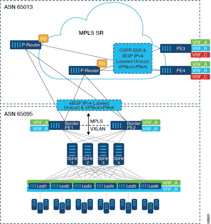
In the following scenario, a single Data Center Fabric running VXLAN EVPN is depicted. The VRFs (VRF_A, VRF_B) present in the Data Center require to be extended over a WAN/Core running MPLS-based Segment Routing (MPLS-SR). The Data Center Fabric’s Border switches act as Border Provider Edge (Border PE1, Border PE2) interconnecting VXLAN BGP EVPN with MPLS-SR with L3VPN (VPNv4/VPNv6). The BPEs are interconnected with the Provider Router (P-Router) via eBGP using the IPv4 Labeled-Unicast as well as the VPNv4/VPNv6 Address-Family (AF). The P-Router acts as BGP Route-Reflector for the mentioned AF and relays the necessary routes to the MPLS-SR Provider Edge (PE3, PE4) via iBGP. Beyond the usage of BGP as the control plane, the MPLS-SR nodes within the same Autonomous System (AS) use an IGP (OSPF or ISIS) for label distribution. From the PEs shown in the above figure (PE3, PE4), Inter-AS Option A can be used to extend the Data Center or Core network VRFs to another external network. Even though this diagram shows only one Data Center, the MPLS-SR network can interconnect multiple Data Center Fabrics.
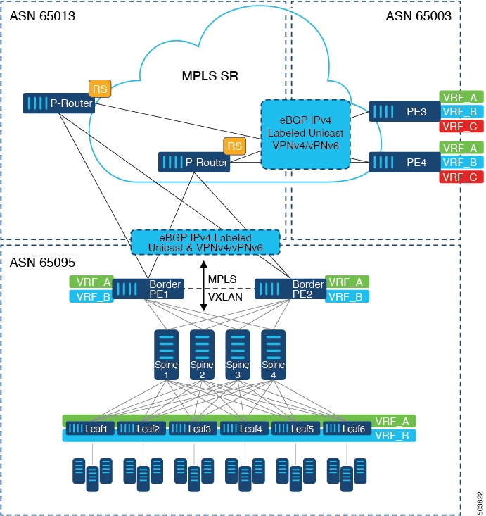
An alternative deployment scenario is when the Core network is separated into multiple Administrative Domains or Autonomous Systems (AS). In the above figure, a single Data Center Fabric running VXLAN EVPN is depicted. The VRFs (VRF_A, VRF_B) present in the Data Center require to be extended over a WAN/Core running MPLS-based Segment Routing (MPLS-SR). The Data Center Fabric’s Border switches act as Border Provider Edge (Border PE1, Border PE2) interconnecting VXLAN BGP EVPN with MPLS-SR with L3VPN (VPNv4/VPNv6). The BPEs are interconnected with the Provider Router (P-Router) via eBGP using the IPv4 Labeled-Unicast as well as the VPNv4/VPNv6 Address-Family (AF). The P-Router acts as BGP Route Server for the mentioned AF and relays the necessary routes to the MPLS-SR Provider Edge (PE3, PE4) via eBGP; no other control-plane protocol is used between the MPLS-SR nodes. Similar to the previous scenario, the PEs (PE3, PE4) can operate with Inter-AS Option A to extend the Data Center or Core network VRFs to an external network. Even though this diagram shows only one Data Center, the MPLS-SR network can interconnect multiple Data Center Fabrics.
Beginning with Cisco NX-OS Release 10.3(1)F, DSCP Based SRTE Traffic Steering is supported on the border PE. For more information, see Configuring DSCP Based SRTE Traffic Steering. This scenario is supported only with L3VPN (MPLS SR). In the above diagram, which represents the border PE (border leaf) scenario, note the following:
-
The incoming VXLAN traffic is terminated and then sent into L3VPN (MPLS SR) so that it follows the standard routing best-path to PE3 or PE4.
-
Incoming VXLAN traffic entering PE1 is terminated, and the SRTE traffic steering policy applied on L3 VNI overrides the standard routing best-path and steers traffic along an alternate path to PE3 or PE4 based on the SRTE flow steering policy.
For additional information on MPLS SR, see the Cisco Nexus 9000 Series NX-OS Label Switching Configuration Guide.
 Feedback