Information About VXLAN QoS
VXLAN QoS enables you to provide Quality of Service (QoS) capabilities to traffic that is tunneled in VXLAN.
-
Classification traffic to assign different properties.
-
Including traffic marking with different priorities.
-
Queuing traffic to enable priority for the protected traffic.
-
Policing for misbehaving traffic.
-
Shaping for traffic that limits speed per interface.
-
Properties traffic sensitive to traffic drops.
Additional Information About VXLAN QoS
QoS allows you to classify the network traffic, police and prioritize the traffic flow, and provide congestion avoidance.
For more information about QoS, see the following guides:
VXLAN QoS Terminology
|
Term |
Definition |
|---|---|
|
Frames |
Carries traffic at Layer 2. Layer 2 frames carry Layer 3 packets. |
|
Packets |
Carries traffic at Layer 3. |
|
VXLAN packet |
Carries original frame, encapsulated in VXLAN IP/UDP header. |
|
Original frame |
A Layer 2 or Layer 2 frame that carries the Layer 3 packet before encapsulation in a VXLAN header. |
|
Decapsulated frame |
A Layer 2 or a Layer 2 frame that carries a Layer 3 packet after the VXLAN header is decapsulated. |
|
Ingress VTEP |
The point where traffic is encapsulated in the VXLAN header and enters the VXLAN tunnel. |
|
Egress VTEP |
The point where traffic is decapsulated from the VXLAN header and exits the VXLAN tunnel. |
|
Class of Service (CoS) |
Refers to the three bits in an 802.1Q header that are used to indicate the priority of the Ethernet frame as it passes through a switched network. The CoS bits in the 802.1Q header are commonly referred to as the 802.1p bits. 802.1Q is discarded prior to frame encapsulation in a VXLAN header, where CoS value is not present in VXLAN tunnel. To maintain QoS when a packet enters the VXLAN tunnel, the type of service (ToS) and CoS values map to each other. |
|
IP precedence |
The 3 most significant bits of the ToS byte in the IP header. |
|
Differentiated Services Code Point (DSCP) |
The first six bits of the ToS byte in the IP header. DSCP is only present in an IP packet. |
|
Explicit Congestion Notification (ECN) |
The last two bits of the ToS byte in the IP header. ECN is only present in an IP packet. |
|
QoS tags |
Prioritization values carried in Layer 3 packets and Layer 2 frames. A Layer 2 CoS label can have a value ranging between zero for low priority and seven for high priority. A Layer 3 IP precedence label can have a value ranging between zero for low priority and seven for high priority. IP precedence values are defined by the three most significant bits of the 1-byte ToS byte. A Layer 3 DSCP label can have a value between 0 and 63. DSCP values are defined by the six most significant bits of the 1-byte IP ToS field. |
|
Classification |
The process used for selecting traffic for QoS |
|
Marking |
The process of setting: a Layer 2 COS value in a frame, Layer 3 DSCP value in a packet, and Layer 3 ECN value in a packet. Marking is also the process of choosing different values for the CoS, DSCP, ECN field to mark packets so that they have the priority that they require during periods of congestion. |
|
Policing |
Limiting bandwidth used by a flow of traffic. Policing can mark or drop traffic. |
|
MQC |
The Cisco Modular QoS command line interface (MQC) framework, which is a modular and highly extensible framework for deploying QoS. |
VXLAN QoS Features
The following topics describe the VXLAN QoS features that are supported in a VXLAN network:
Trust Boundaries
The trust boundary forms a perimeter on your network. Your network trusts (and does not override) the markings on your switch. The existing ToS values are trusted when received on in the VXLAN fabric.
Classification
Classification partitions network traffic into classes based on port characteristics or packet header fields, including IP precedence, DSCP, Layer 3 to Layer 4 parameters, and packet length.
-
Match criteria: The values used to classify traffic are called match criteria.
-
Multiple match criteria: When defining a traffic class, you can specify multiple match criteria, choose not to match on a particular criterion, or determine the traffic class by matching any or all criteria.
-
Default class: Traffic that fails to match any class is assigned to a default traffic class called
class-default.
Marking
Marking sets QoS information associated with a packet. Packet marking allows you to partition your network into multiple priority levels or classes of service. You can set the value of a standard QoS field for Class of Service (CoS), IP precedence, and DSCP. You can also set the QoS field for internal labels (such as QoS groups) that can be used in subsequent actions. Marking QoS groups identifies the traffic type for queuing and scheduling traffic.
-
Partition the network into multiple priority levels or classes of service.
-
Set the value of a standard QoS field for CoS, IP precedence, and DSCP.
-
Set the QoS field for internal labels (such as QoS groups) for use in subsequent actions.
Policing
Policing causes traffic that exceeds the configured rate to be discarded or marked down to a higher drop precedence.
-
Single-rate policers monitor the specified committed information rate (CIR) of traffic.
-
Dual-rate policers monitor both CIR and peak information rate (PIR) of traffic.
Queuing and Scheduling
The queuing and scheduling process allows you to control the queue usage and the bandwidth that is allocated to traffic classes. You can then achieve the desired trade-off between throughput and latency.
-
You can limit the size of the queues for a particular class of traffic by applying either static or dynamic limits.
-
You can apply weighted random early detection (WRED) to a class of traffic, which allows packets to be dropped based on the QoS group. The WRED algorithm allows you to perform proactive queue management to avoid traffic congestion.
-
ECN can be enabled along with WRED on a particular class of traffic to mark the congestion state instead of dropping the packets. ECN marking in the VXLAN tunnel is performed in the outer header, and at the Egress VTEP is copied to decapsulated frame.
Traffic Shaping
You can shape traffic by imposing a maximum data rate on a class of traffic so that excess packets are retained in a queue to smooth (constrain) the output rate. In addition, minimum bandwidth shaping can be configured to provide a minimum guaranteed bandwidth for a class of traffic.
How does traffic shaping work?
Traffic shaping regulates and smooths out the packet flow by imposing a maximum traffic rate for each port’s egress queue. Packets that exceed the threshold are placed in the queue and are transmitted later. Traffic shaping is similar to Traffic Policing, but the packets are not dropped. Because packets are buffered, traffic shaping minimizes packet loss (based on the queue length), which provides better traffic behavior for TCP traffic.
By using traffic shaping, you can control the following:
-
Access to available bandwidth.
-
Ensure that traffic conforms to the policies established for it.
-
Regulate the flow of traffic to avoid congestion that can occur when the egress traffic exceeds the access speed of its remote, target interface.
Network QoS
The network QoS policy defines the characteristics of each CoS value, which are applicable network wide across switches.
-
Pause behavior—You can decide whether a CoS requires the lossless behavior which is provided by using a priority flow control (PFC) mechanism that prevents packet loss during congestion) or not. You can configure drop (frames with this CoS value can be dropped) and no drop (frames with this CoS value cannot be dropped). For the drop and no drop configuration, you must also enable PFC per port. For more information about PFC, see “Configuring Priority Flow Control".
Pause behavior can be achieved in the VXLAN tunnel for a specific queue-group.
VXLAN Priority Tunneling
In the VXLAN tunnel, DSCP values in the outer header are used to provide QoS transparency in end-to-end of the tunnel. The outer header DSCP value is derived from the DSCP value with Layer 3 packets or the CoS value for Layer 2 frames. At the VXLAN tunnel egress point, the priority of the decapsulated traffic is chosen based on the mode. For more information, see Decapsulated Packet Priority Selection.
-
DSCP values in the outer header provide QoS transparency.
-
Outer header DSCP is derived from Layer 3 DSCP or Layer 2 CoS values.
-
Priority of decapsulated traffic at egress is mode-dependent.
MQC CLI
The Modular QoS CLI (MQC) allows you to define traffic classes (class maps), create and configure traffic policies (policy maps), and perform actions that are defined in the policy maps to interface (service policy).
-
Define traffic classes (class maps)
-
Create and configure traffic policies (policy maps)
-
Perform actions that are defined in the policy maps to interface (service policy)
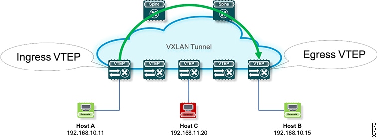
VXLAN QoS Topology and Roles
In the VXLAN network, points of interest are ingress VTEPs where the original traffic is encapsulated in a VXLAN header. Spines are transporting hops that connect ingress and egress VTEPs. An egress VTEP is the point where VXLAN encapsulated traffic is decapsulated and egresses the VTEP as classical Ethernet traffic.
-
Ingress VTEP: Encapsulates original traffic in a VXLAN header.
-
Spine: Transports traffic between ingress and egress VTEPs.
-
Egress VTEP: Decapsulates VXLAN traffic and outputs as Ethernet.
VXLAN QoS Topology Reference
The network is bidirectional, but in the previous image, traffic is moving left to right.
Key roles in the VXLAN QoS topology include:
-
Ingress VTEP
-
Spine
-
Egress VTEP
 Note |
Ingress and egress VTEPs are the boundary between the VXLAN tunnel and the IP network. |
The following figure shows the VXLAN network topology:
Ingress VTEP and Encapsulation in the VXLAN Tunnel
At the ingress VTEP, the VTEP processes packets as follows:
Summary
The ingress VTEP receives Layer 2 or Layer 3 traffic, classifies and marks packets based on QoS policies, determines the next hop, and encapsulates packets with VXLAN headers for forwarding through the VXLAN tunnel.
-
Ingress VTEP: Receives and classifies incoming traffic, applies QoS markings, and encapsulates packets into VXLAN headers.
-
Switch: Forwards encapsulated packets through the VXLAN tunnel based on routing and QoS parameters.
This process ensures that traffic entering the VXLAN fabric is properly encapsulated, marked, and forwarded according to QoS and routing policies.
Workflow
These stages describe how the ingress VTEP processes and encapsulates packets in the VXLAN tunnel.
- Layer 2 or Layer 3 traffic enters the edge of the VXLAN network.
- The switch receives the traffic from the input interface and uses the 802.1p bits or the DSCP value to perform any classification, marking, and policing. It also derives the outer DSCP value in the VXLAN header. For classification of incoming IP packets, the input service policy can also use access control lists (ACLs).
- For each incoming packet, the switch performs a lookup of the IP address to determine the next hop.
- The packet is encapsulated in the VXLAN header. The encapsulated packet's VXLAN header is assigned a DSCP value that is based on QoS rules.
- The switch forwards the encapsulated packets to the appropriate output interface for processing.
- The encapsulated packets, marked by the DSCP value, are sent to the VXLAN tunnel output interface.
Transporting VXLAN Packets
In the transport through a VXLAN tunnel, the switch processes the VXLAN packets as follows:
Summary
The switch receives VXLAN-encapsulated packets, performs header-based classification and forwarding decisions, and sends the packets through the appropriate output interface for transport across the VXLAN tunnel.
Workflow
These stages describe how VXLAN encapsulated packets are processed and forwarded through the tunnel.
- The VXLAN encapsulated packets are received on an input interface of a transport switch. The switch uses the outer header to perform classification, marking, and policing.
- The switch performs a lookup on the IP address in the outer header to determine the next hop.
- The switch forwards the encapsulated packets to the appropriate output interface for processing.
- VXLAN sends encapsulated packets through the output interface.
Egress VTEP and Decapsulation of the VXLAN Tunnel
At the egress VTEP boundary of the VXLAN tunnel, the VTEP processes packets as follows:
Summary
The egress VTEP receives VXLAN-encapsulated packets, removes the VXLAN header, and performs forwarding decisions based on the inner headers. The switch applies QoS marking and policing, assigns DSCP values as required, and sends the decapsulated packets to the destination network through the appropriate output interface.
Workflow
- Packets encapsulated in VXLAN are received at the NVE interface of an egress VTEP, where the switch uses the inner header DSCP value to perform classification, marking, and policing.
- The switch removes the VXLAN header from the packet, and does a lookup that is based on the decapsulated packet's headers.
- The switch forwards the decapsulated packets to the appropriate output interface for processing.
- Before the packet is sent out, a DSCP value is assigned to a Layer 3 packet based on the decapsulation priority or based on marking Layer 2 frames.
- The decapsulated packets are sent through the outgoing interface to the IP network.
Classification at the Ingress VTEP, Spine, and Egress VTEP
IP to VXLAN
At the ingress VTEP, the ingress point of the VXLAN tunnel, traffic is encapsulated in the VXLAN header. Traffic on an ingress VTEP is classified based on the priority in the original header. Classification can be performed by matching the CoS, DSCP, and IP precedence values or by matching traffic with the ACL based on the original frame data.
-
Classification can be performed by matching the CoS, DSCP, and IP precedence values.
-
Classification can also be performed by matching traffic with the ACL based on the original frame data.
-
For Layer 2 frames without the IP header, the DSCP value of the outer header is derived from the CoS-to-DSCP mapping present in the hardware.
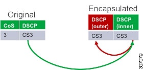
Preservation of QoS Attributes in VXLAN Encapsulation
When traffic is encapsulated in the VXLAN, the Layer 3 packet's DSCP value is copied from the original header to the outer header of the VXLAN encapsulated packet.
For Layer 2 frames without the IP header, the DSCP value of the outer header is derived from the CoS-to-DSCP mapping present in the hardware illustrated in Default Settings for VXLAN QoS. In this way, the original QoS attributes are preserved in the VXLAN tunnel.
This behavior is illustrated in the following figures:
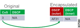
A Layer 2 frame does not have a DSCP value present because the IP header is not present in the frame. After a Layer 2 frame is encapsulated, the original CoS value is not preserved in the VXLAN tunnel.
Inside the VXLAN Tunnel
Inside the VXLAN tunnel, traffic classification is based on the outer header DSCP value. Classification can be done matching the DCSP value or using ACLs for classification.
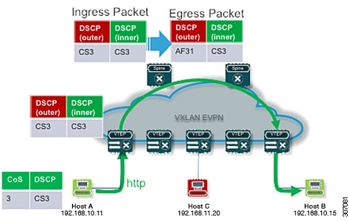
Marking and QoS Behavior in VXLAN Tunnels
If VXLAN encapsulated traffic is crossing the trust boundary, marking can be changed in the packet to match QoS behavior in the tunnel. Marking can be performed inside of the VXLAN tunnel, where a new DSCP value is applied only on the outer header. The new DSCP value can influence different QoS behaviors inside the VXLAN tunnel. The original DSCP value is preserved in the inner header.
Key points about marking and QoS behavior in VXLAN tunnels:
-
Marking can be changed when crossing the trust boundary.
-
A new DSCP value is applied only on the outer header.
-
The original DSCP value is preserved in the inner header.
The following figure illustrates marking inside of the VXLAN tunnel:
VXLAN to IP
Classification at the egress VTEP is performed for traffic leaving the VXLAN tunnel. For classification at the egress VTEP, the inner header values are used. The inner DSCP value is used for priority-based classification. Classification can be performed using ACLs.
-
Classification is performed on the NVE interface for all VXLAN tunneled traffic.
-
Marking and policing can be performed on the NVE interface for tunneled traffic.
-
If marking is configured, newly marked values are present in the decapsulated packet. Because the original CoS value is not preserved in the encapsulated packet, marking can be performed for decapsulated packets for any devices that expect an 802.1p field for QoS in the rest of the network.
Decapsulated Packet Priority Selection
At the egress VTEP, the VXLAN header is removed from the packet and the decapsulated packet egresses the switch with the DSCP value. The switch assigns the DSCP value of the decapsulated packet based on two modes:
-
Uniform mode – the DSCP value from the outer header of the VXLAN packet is copied to the decapsulated packet. Any change of the DSCP value in the VXLAN tunnel is preserved and present in the decapsulated packet. Uniform mode is the default mode of decapsulated packet priority selection.
Figure 5. Uniform Mode Outer DSCP Value is Copied to Decapsulated Packet DSCP Value for a Layer-3 Packet 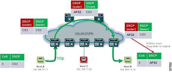
-
Pipe mode – the original DSCP value is preserved at the VXLAN tunnel end. At the egress VTEP, the system copies the inner DSCP value to the decapsulated packet DSCP value. In this way, the original DSCP value is preserved at the end of the VXLAN tunnel.
Figure 6. Pipe Mode Inner DSCP Value is Copied to Decapsulated Packet DSCP Value for Layer-3 Packet 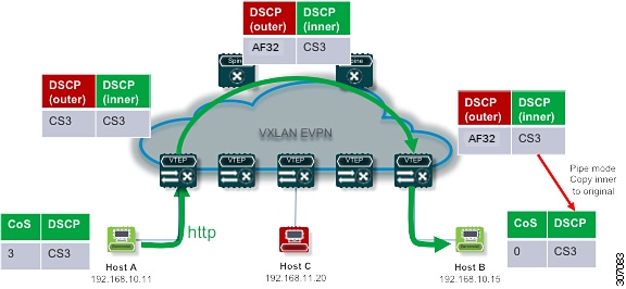
 Feedback