External Layer 3 connections for VXLAN BGP EVPN fabrics
External Layer 3 connections are network extension methods that
-
use per-VRF IP routing to provide connectivity between a VXLAN BGP EVPN fabric and external networks,
-
commonly implement VRF Lite or Inter-AS Option A for Layer 3 extension, and
-
enable scalable, segmented, and secure inter-domain routing across data center boundaries.
The terms “VRF Lite” and “Inter-AS Option A” both refer to techniques for back-to-back VRF connectivity. These enable the logical separation of traffic and policy controls at the peering boundaries of two domains (such as between a data center fabric and an external IP/MPLS backbone).
For example, connecting a tenant VRF in the VXLAN BGP EVPN fabric to a WAN router via a point-to-point link using VRF Lite enables the tenant to communicate externally while maintaining traffic separation from other tenants.
VXLAN BGP EVPN fabrics and VRF-lite mechanisms
A VXLAN BGP EVPN fabric is a network overlay architecture that:
-
enables scalable Layer 2 and Layer 3 segmentation across a data center network,
-
uses MP-BGP with the EVPN address family as the control plane for route exchange between all edge devices (VTEPs) and route reflectors, and
-
supports external connectivity by exporting prefixes from MP-BGP EVPN to IPv4/IPv6 per-VRF peerings toward external routers.
External connectivity and per-VRF peering in VXLAN BGP EVPN fabrics
In this architecture, the Edge devices (VTEPs) acting as border nodes handle external routing tasks. Various routing protocols can be used for per-VRF peering. eBGP is typically preferred, but IGPs such as OSPF, IS-IS, or EIGRP can be used if redistribution is implemented.

Guidelines for external VRF connectivity and route leaking
-
External VRF connectivity is supported on Cisco Nexus 9504 and 9508 platform switches with Cisco Nexus 96136YC-R and 9636C-RX line cards.
-
Use a physical Layer 3 interface (parent interface) for external Layer 3 connectivity (VRF default) if permitted.
-
Beginning with Cisco NX-OS Release 9.3(5), configure VTEPs to support VXLAN-encapsulated traffic only over parent interfaces if subinterfaces are configured.
-
Do not use a parent interface to multiple subinterfaces for external Layer 3 connectivity (such as Ethernet1/1 for a VRF default). Use a subinterface instead.
-
Do not configure VTEPs to support VXLAN-encapsulated traffic over subinterfaces, regardless of VRF participation or IEEE 802.1Q encapsulation.
-
Do not mix subinterfaces for VXLAN and non-VXLAN VLANs.
-
Do not use the import map command under address-family ipv4 unicast to control what gets imported into the EVPN table L3VNI counterpart.
-
If TRM is configured, do not use SVIs to interconnect to the external router.
VXLAN BGP EVPN with eBGP for VRF-lite
Configure a VRF for VXLAN routing and external connectivity using BGP
Use this task when you need to enable inter-VRF or external connectivity for tenants in a VXLAN-based fabric.
Before you begin
Ensure you have:
-
Access the device with appropriate privileges.
-
Identified required VRF names, VNI numbers, and BGP configuration details.
Procedure
|
Step 1 |
Enter configuration mode: configure terminal |
|
Step 2 |
Create or select the VRF context: vrf context vrf-name |
|
Step 3 |
Specify the Layer 3 VNI for the VRF: vni number The VNI associated with the VRF is often referred to as a Layer 3 VNI, L3VNI, or L3VPN. The L3VNI is configured as the common identifier across the participating VTEPs. |
|
Step 4 |
Assign a route distinguisher (RD): rd {auto | rd} RD uniquely identifies a VTEP within an L3VNI. Supported formats: ASN2:NN, ASN4:NN, or IPV4:NN. |
|
Step 5 |
Configure the address family for either IPv4 or IPv6: address-family ipv4 unicast or address-family ipv6 unicast Sets up the specified IPv4 or IPv6 unicast address family. |
|
Step 6 |
Set the route target (RT) for import and export: route-target both {auto | rt} RT is used for per-VRF prefix import and export policy. Supported formats: ASN2:NN, ASN4:NN, or IPV4:NN. Manually configured RTs are required to support asymmetric VNIs. |
|
Step 7 |
(Optional) Set RTs specifically for EVPN: route-target both {auto | rt} evpn |
|
Step 8 |
Repeat steps 2 to 7 for each required L3VNI. |
The VRF and associated Layer 3 VNI(s) are configured on the border node, ready for VXLAN routing and connectivity via BGP. For a configuration example, see Example of VXLAN BGP EVPN eBGP VRF-lite connectivity.
What to do next
Verify the configuration and ensure BGP neighbors are established.
Configure the L3VNI fabric-facing VLAN and SVI on the border node
Before you begin
Ensure you have:
-
Access the device with appropriate privileges.
-
Identified the required VLAN ID, VN-Segment ID, SVI number, IP addresses, and VRF context for each L3VNI.
Use this procedure to configure a VLAN and SVI in global configuration mode for VXLAN EVPN L3VNI routing on a border node.
Procedure
|
Step 1 |
Create the VLAN for the L3VNI: vlan vlan_id |
|
Step 2 |
Map the L3VNI to the VLAN for VXLAN EVPN routing: vn-segment vn_segment_id |
|
Step 3 |
Configure the SVI (Switch Virtual Interface) for the VLAN: interface vlan svi_number |
|
Step 4 |
Set the MTU value for VXLAN requirements: mtu mtu_value The recommended MTU is 9216. |
|
Step 5 |
Associate the SVI with the required VRF context: vrf member vrf_name |
|
Step 6 |
Disable ICMP redirects: no ip redirects |
|
Step 7 |
Enable IPv4 forwarding on the interface: ip forward |
|
Step 8 |
(Optional) Assign the IPv6 address to the SVI: ipv6 address ipv6_address |
|
Step 9 |
Disable ICMPv6 redirects: no ipv6 redirects |
The L3VNI is mapped to a VLAN and SVI on the border node, with appropriate VRF and forwarding settings for VXLAN EVPN routing. For a configuration example, see Example of VXLAN BGP EVPN eBGP VRF-lite connectivity.
What to do next
Repeat this process for each required L3VNI.
Configure the VTEP on the border node
Before you begin
Ensure you have administrator access to the switch.
Procedure
|
Step 1 |
Enter global configuration mode: configure terminal |
|
Step 2 |
Access the NVE interface configuration mode: interface nve1 |
|
Step 3 |
Add the Layer 3 VNI to the overlay and associate it with the appropriate tenant VRF: member vni vni associate-vrf Repeat this command for each tenant VRF by replacing the vni with the required VNI number. |
The border node VTEP is configured for all required tenant VRFs with their associated Layer-3 VNIs. For a configuration example, see Example of VXLAN BGP EVPN eBGP VRF-lite connectivity.
Configure a BGP VRF instance for IPv4 per-VRF peering on the border node
Perform this procedure on each border node that participates in the fabric to support external IPv4 connectivity for specific VRFs.
Before you begin
Ensure you have:
-
Access to the device with appropriate privileges.
-
A list of VRF names (L3VNIs) that require IPv4 peering.
-
Autonomous system (AS) numbers and neighbor IP addresses.
Procedure
|
Step 1 |
Enter global configuration mode: configure terminal |
||
|
Step 2 |
Create the BGP process using the local AS number: router bgp autonomous-system-number Valid AS number: 1–4294967295. |
||
|
Step 3 |
Configure these settings for each VRF that requires IPv4 peering.
|
||
|
Step 4 |
Exit configuration mode and save your changes. |
The border node is configured for BGP VRF-based IPv4 per-VRF peering and can establish external IPv4 connectivity. For a configuration example, see Example of VXLAN BGP EVPN eBGP VRF-lite connectivity.
What to do next
Verify the BGP configuration and neighbor status.
Configure a BGP VRF instance for IPv6 per-VRF peering on the border node
Perform this procedure on each border node that participates in the fabric to support external IPv6 connectivity for specific VRFs.
Before you begin
Ensure you have:
-
Access to the device with appropriate privileges.
-
A list of VRF names (L3VNIs) that require IPv6 peering.
-
Autonomous system (AS) numbers and neighbor IP addresses.
Procedure
|
Step 1 |
Enter global configuration mode: configure terminal |
||
|
Step 2 |
Create the BGP process using the local AS number: router bgp autonomous-system-number Valid AS number: 1–4294967295. |
||
|
Step 3 |
Configure these settings for each VRF that requires IPv6 peering.
|
||
|
Step 4 |
Exit configuration mode and save your changes. |
The border node is configured for BGP VRF-based IPv6 per-VRF peering and can establish external IPv6 connectivity. For a configuration example, see Example of VXLAN BGP EVPN eBGP VRF-lite connectivity.
What to do next
Verify the BGP configuration and neighbor status.
Configure the sub-interface instance for per-VRF peering on the border node
Use this task when you need to set up per-VRF peering using sub-interfaces for individual VRF contexts on a Cisco NX-OS device.
Before you begin
Ensure you have:
-
Access the device with appropriate privileges.
-
Identified the parent interface, sub-interface identifier, VRF names, VLAN ID, and IP address for each peering.
Procedure
|
Step 1 |
Enter global configuration mode: configure terminal |
|
Step 2 |
Configure the parent interface and enable Layer 3 mode.
|
|
Step 3 |
Configure the sub-interface for the specific VRF peering.
|
|
Step 4 |
Repeat the sub-interface configuration for each additional per-VRF peering. |
The border node is ready for per-VRF peering, with each VRF mapped to a unique sub-interface. For a configuration example, see Example of VXLAN BGP EVPN eBGP VRF-lite connectivity.
What to do next
Verify connectivity and routing for each configured VRF instance.
VXLAN BGP EVPN - default-route, route filtering on external connectivity
Default routes for external connectivity
A default route for external connectivity is a network routing method that:
-
enables outbound traffic to reach destinations outside the local network,
-
uses route advertisements within a VXLAN BGP EVPN fabric to establish a default forwarding path, and
-
incorporates route filtering to prevent default-route propagation beyond intended boundaries.
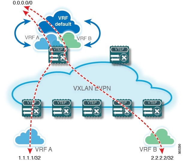
When advertising a default route into a VXLAN BGP EVPN fabric, ensure that the default route remains internal to the fabric and is not advertised externally. Implement route filtering mechanisms to prevent unintended distribution of the default route outside the fabric. This approach maintains the integrity and security of network routing policies.
Configure the default route in the border nodes VRF
Before you begin
-
Identify the VRF name to configure.
-
Identify the next-hop IPv4 address, IPv6 address, or both to use for the default route.
Procedure
|
Step 1 |
Enter global configuration mode: configure terminal |
|
Step 2 |
Specify the VRF context you want to configure: vrf context vrf-name |
|
Step 3 |
Configure the IPv4 default route for the VRF: ip route 0.0.0.0/0 next-hop-ipv4 |
|
Step 4 |
(Optional) Configure the IPv6 default route for the VRF: ipv6 route 0::/0 next-hop-ipv6 |
The specified VRF now includes default IPv4 or IPv6 routes. Packets with unknown destinations are forwarded to the next-hop gateway. For a configuration example, see Route advertisement and filtering features for VXLAN BGP EVPN border nodes.
Configure the BGP VRF instance for IPv4/IPv6 default-route advertisement on the border node
Perform this task on each border node requiring default-route advertisement for external connectivity in environments leveraging Layer 3 virtual networks (L3VNIs).
Before you begin
Ensure you have administrator access to the switch.
Obtain the autonomous system numbers, VRF names, and BGP neighbor information.
Procedure
|
Step 1 |
Enter global configuration mode: |
|
Step 2 |
Configure BGP under the appropriate autonomous system, then specify the VRF: |
|
Step 3 |
Enable the IPv4 unicast address family, then advertise IPv4 default routes within the VRF: |
|
Step 4 |
Enable the IPv6 unicast address family, then advertise IPv4 and IPv6 default routes within the VRF: |
|
Step 5 |
Define the eBGP neighbor and remote AS, and specify the update source interface if required: |
|
Step 6 |
Activate the IPv4 or IPv6 address family for this neighbor: |
|
Step 7 |
(Optional) Attach a route-map for egress route filtering on the neighbor: |
|
Step 8 |
Repeat steps 2–7 for each VRF and L3VNI that require external connectivity and default-route advertisement. |
|
Step 9 |
Save the configuration. |
The BGP VRF instance on the border node now advertises IPv4 and IPv6 default routes to eBGP neighbors, enabling proper external connectivity and route propagation for your VRFs. For a configuration example, see Route advertisement and filtering features for VXLAN BGP EVPN border nodes.
Configure route filtering for IPv4 default-route advertisement
Use this task to prevent a switch from advertising the IPv4 default route via external connectivity, while permitting other routes.
Before you begin
Ensure you have:
-
Access the device with appropriate privileges.
-
Identified required prefix-list names and route-map names.
Procedure
|
Step 1 |
Enter global configuration mode: configure terminal Accesses system configuration to allow changes. |
|
Step 2 |
Create an IPv4 prefix list to identify the default route: ip prefix-list name seq 5 permit 0.0.0.0/0 Defines a filter that matches the IPv4 default route. |
|
Step 3 |
Create a route-map with a deny policy for the default route: route-map name deny 10 Configures the route-map to block advertisements matching the default route. |
|
Step 4 |
Match the prefix list in the route-map: match ip address prefix-list name Associates the prefix-list filter with the deny statement. |
|
Step 5 |
Add a permit policy at the end of the route-map to allow all other routes: route-map name permit 1000 Permits advertisement of routes that do not match the default route. |
The switch filters out IPv4 default routes from advertisement via external connectivity and permits non-default routes. For a configuration example, see Route advertisement and filtering features for VXLAN BGP EVPN border nodes.
What to do next
Verify route advertisements using appropriate show commands and monitor routing updates to confirm correct filtering.
Configure route filtering for IPv6 default-route advertisement
Use this task to prevent a switch from advertising the IPv6 default route via external connectivity, while permitting other routes.
Before you begin
Ensure you have:
-
Access the device with appropriate privileges.
-
Identified required prefix-list names and route-map names.
Procedure
|
Step 1 |
Enter global configuration mode: configure terminal Accesses system configuration to allow changes. |
|
Step 2 |
Create an IPv6 prefix list to identify the default route: ipv6 prefix-list name seq 5 permit 0::/0 Defines a filter that matches the IPv6 default route. |
|
Step 3 |
Create a route-map with a deny policy for the default route: route-map name deny 10 Configures the route-map to block advertisements matching the default route. |
|
Step 4 |
Match the IPv6 prefix list in the route-map: match ipv6 address prefix-list name Associates the prefix-list filter with the deny statement. |
|
Step 5 |
Add a permit policy at the end of the route-map to allow all other routes: route-map name permit 1000 Permits advertisement of routes that do not match the default route. |
The switch filters out IPv6 default routes from advertisement via external connectivity and permits non-default routes. For a configuration example, see Route advertisement and filtering features for VXLAN BGP EVPN border nodes.
What to do next
Verify route advertisements using appropriate show commands and monitor routing updates to confirm correct filtering.
Default-route distribution and host-route filters
A default-route distribution and host-route filter is a route management feature in VXLAN BGP EVPN fabrics that:
-
advertises all known routes to external network connections by default,
-
allows selective filtering to prevent advertisement of IPv4 /32 or IPv6 /128 host routes when not beneficial, and
-
helps administrators control which routes are shared externally to optimize scalability and network policy enforcement.
In some network scenarios, advertising specific host routes (such as IPv4 /32 or IPv6 /128) to external networks can lead to unnecessary complexity or resource usage. The host-route filter feature enables precise control over which routes are included in external advertisements, supporting streamlined connectivity and efficient network management.
If a network only requires default routes to be advertised externally, administrators can enable host-route filtering to suppress unnecessary host-specific routes, reducing the size and complexity of the route table advertised to upstream peers.
Without applying host-route filters, a VXLAN BGP EVPN fabric might share all detailed host routes externally, which can overwhelm upstream devices and result in suboptimal routing decisions.
Configure the BGP VRF instance for IPv4/IPv6 host-route filtering on the border node
This task enables granular route filtering by configuring BGP for designated VRFs with route-maps.
Before you begin
Ensure you have:
-
Access to the device with appropriate privileges.
-
Required autonomous system (AS) number, VRF names, neighbor IP addresses, remote AS numbers, and interface identifiers.
-
Preconfigured route-maps (for example, "permitall").
Procedure
|
Step 1 |
Enter global configuration mode: configure terminal |
|
Step 2 |
Configure BGP with your AS number: router bgp autonomous-system-number Initializes BGP process for your AS. |
|
Step 3 |
Specify the VRF to configure: vrf vrf-name |
|
Step 4 |
Define the eBGP neighbor and remote AS: neighbor IP address remote-as remote-AS-number Sets up peering with an external BGP neighbor. |
|
Step 5 |
Specify the update-source interface for peering: update-source interface |
|
Step 6 |
Activate the IPv4 or IPv6 address family for prefix exchange: address-family {ipv4 | ipv6} unicast |
|
Step 7 |
Attach a route-map for egress route filtering: route-map route-map-name out |
|
Step 8 |
Repeat steps 3 to 7 for each L3VNI that requires host-route filtering. |
The border node BGP VRF instances are configured with host-route filtering for IPv4/IPv6 as specified, applying the selected route-maps. For a configuration example, see Route advertisement and filtering features for VXLAN BGP EVPN border nodes.
Configure route filtering for IPv4 host-route advertisement
Use this task to prevent a switch from advertisement of IPv4 host routes by configuring prefix lists and route maps.
Before you begin
Ensure you have:
-
Access the device with appropriate privileges.
-
Identified required prefix-list names and route-map names.
Procedure
SUMMARY STEPS
- Enter global configuration mode: configure terminal
- Create an IPv4 prefix list to identify the default route: ip prefix-list name seq 5 permit 0.0.0.0/0 eq 32
- Create a route-map with a deny policy for the host route: route-map name deny 10
- Match the prefix list in the route-map: match ip address prefix-list name
- Add a permit policy at the end of the route-map to allow all other routes: route-map name permit 1000
DETAILED STEPS
|
Step 1 |
Enter global configuration mode: configure terminal Accesses system configuration to allow changes. |
|
Step 2 |
Create an IPv4 prefix list to identify the default route: ip prefix-list name seq 5 permit 0.0.0.0/0 eq 32 Defines a filter that matches the IPv4 host route. |
|
Step 3 |
Create a route-map with a deny policy for the host route: route-map name deny 10 Configures the route-map to block advertisements matching the host route. |
|
Step 4 |
Match the prefix list in the route-map: match ip address prefix-list name Associates the prefix-list filter with the deny statement. |
|
Step 5 |
Add a permit policy at the end of the route-map to allow all other routes: route-map name permit 1000 Permits advertisement of routes that do not match the host route. |
The IPv4 host-route is filtered and will not be advertised via external connectivity. For a configuration example, see Route advertisement and filtering features for VXLAN BGP EVPN border nodes .
Configure route filtering for IPv6 host-route advertisement
Use this task to prevent a switch from advertisement of IPv6 host routes by configuring prefix lists and route maps.
Before you begin
Ensure you have:
-
Access the device with appropriate privileges.
-
Identified required prefix-list names and route-map names.
Procedure
SUMMARY STEPS
- Enter global configuration mode: configure terminal
- Create an IPv6 prefix list to identify the default route: ipv6 prefix-list name seq 5 permit 0::/0 eq 128
- Create a route-map with a deny policy for the host route: route-map name deny 10
- Match the IPv6 prefix list in the route-map: match ipv6 address prefix-list name
- Add a permit policy at the end of the route-map to allow all other routes: route-map name permit 1000
DETAILED STEPS
|
Step 1 |
Enter global configuration mode: configure terminal Accesses system configuration to allow changes. |
|
Step 2 |
Create an IPv6 prefix list to identify the default route: ipv6 prefix-list name seq 5 permit 0::/0 eq 128 Defines a filter that matches the IPv6 host route. |
|
Step 3 |
Create a route-map with a deny policy for the host route: route-map name deny 10 Configures the route-map to block advertisements matching the host route. |
|
Step 4 |
Match the IPv6 prefix list in the route-map: match ipv6 address prefix-list name Associates the prefix-list filter with the deny statement. |
|
Step 5 |
Add a permit policy at the end of the route-map to allow all other routes: route-map name permit 1000 Permits advertisement of routes that do not match the host route. |
The IPv6 host route is filtered and will not be advertised via external connectivity. For a configuration example, see Route advertisement and filtering features for VXLAN BGP EVPN border nodes .
Example of VXLAN BGP EVPN eBGP VRF-lite connectivity
This example demonstrates how to establish external connectivity from a VXLAN BGP EVPN fabric to an external router using eBGP and VRF-lite.
Key configuration facts:
-
The VXLAN BGP EVPN border node acts as the neighbor device to the external router.
-
You can configure a local VRF name on the border node that is different from the VRF name on the external router. The L3VNI, however, must remain consistent across the VXLAN BGP EVPN fabric.
-
The configuration supports both IPv4 and IPv6 (dual-stack); you can use either protocol as needed.
Example configuration:
vrf context myvrf_50001
  vni 50001
  rd auto
  address-family ipv4 unicast
    route-target both auto
    route-target both auto evpn
  address-family ipv6 unicast
    route-target both auto
    route-target both auto evpn
!
vlan 2000
  vn-segment 50001
!
interface Vlan2000
  no shutdown
  mtu 9216
  vrf member myvrf_50001
  no ip redirects
  ip forward
  ipv6 address use-link-local-only
  no ipv6 redirects
!
interface nve1
  no shutdown
  host-reachability protocol bgp
  source-interface loopback1
  member vni 50001 associate-vrf
!
router bgp 65002
  vrf myvrf_50001
    router-id 192.0.2.6
    address-family ipv4 unicast
      advertise l2vpn evpn
      maximum-paths ibgp 2
      maximum-paths 2
    address-family ipv6 unicast
      advertise l2vpn evpn
      maximum-paths ibgp 2
      maximum-paths 2
    neighbor 192.0.2.95
      remote-as 65099
      address-family ipv4 unicast
    neighbor 2001:DB8::95/64
      remote-as 65099
      address-family ipv4 unicast
!
interface Ethernet1/3
  no switchport
  no shutdown
interface Ethernet1/3.2
  encapsulation dot1q 2
  vrf member myvrf_50001
  ip address 192.0.2.31/24
  ipv6 address 2001:DB8::31/64
  no shutdown
Route advertisement and filtering features for VXLAN BGP EVPN border nodes
Key features:
-
Advertises IPv4 0.0.0.0/0 and IPv6 ::/0 default routes from the fabric to external peers.
-
Filters host routes (IPv4 /32 and IPv6 /128) to prevent advertising them to external routers.
-
Allows use of prefix lists and route maps in BGP configurations to selectively permit or deny route advertisements.
Configuration summary:
-
Prefix lists for default and host routes. ip prefix-list default-route seq 5 permit 0.0.0.0/0 le 1 ipv6 prefix-list default-route-v6 seq 5 permit 0::/0 ! ip prefix-list host-route seq 5 permit 0.0.0.0/0 eq 32 ipv6 prefix-list host-route-v6 seq 5 permit 0::/0 eq 128 -
Route maps to control route advertisement. route-map extcon-rmap-filter deny 10 match ip address prefix-list default-route route-map extcon-rmap-filter deny 20 match ip address prefix-list host-route route-map extcon-rmap-filter permit 1000 ! route-map extcon-rmap-filter-v6 deny 10 match ipv6 address prefix-list default-route-v6 route-map extcon-rmap-filter-v6 deny 20 match ip address prefix-list host-route-v6 route-map extcon-rmap-filter-v6 permit 1000 -
Static default routes in the VRF. vrf context myvrf_50001 ip route 0.0.0.0/0 192.0.2.1 ipv6 route 0::/0 2001:DB8::95/64 -
Applying route maps to BGP neighbors. router bgp 65002 vrf myvrf_50001 address-family ipv4 unicast network 0.0.0.0/0 address-family ipv6 unicast network 0::/0 neighbor 192.0.2.1 remote-as 65099 address-family ipv4 unicast route-map extcon-rmap-filter out neighbor 2001:DB8::1/64 remote-as 65099 address-family ipv4 unicast route-map extcon-rmap-filter-v6 out
VXLAN BGP EVPN border nodes enable effective control of route advertisements to external peers, improving security and network efficiency by allowing only designated routes.
External router configuration reference
External routers connect to the VXLAN BGP EVPN border node. These routers require specific configuration settings to ensure proper integration. The essential parameters are as follows:
-
VRF name: The VRF name is local to each device. It does not need to match the VRF name used within the VXLAN BGP EVPN fabric, but should be used consistently throughout the configuration for clarity.
-
Address family support: The router supports both IPv4 and IPv6 for dual-stack operation. You can configure either protocol as needed for your deployment.
-
Interface and neighbor settings: Interfaces can be configured with dot1q encapsulation and assigned to the chosen VRF. Neighbor relationships are established for both IPv4 and IPv6 peers.
Example configuration:
vrf context myvrf_50001
!
router bgp 65099
  vrf myvrf_50001
    address-family ipv4 unicast
      maximum-paths 2
    address-family ipv6 unicast
      maximum-paths 2
    neighbor 192.0.2.31
      remote-as 65002
      address-family ipv4 unicast
    neighbor 2001:DB8::1/64
      remote-as 65002
      address-family ipv4 unicast
!
interface Ethernet1/3
  no switchport
  no shutdown
interface Ethernet1/3.2
  encapsulation dot1q 2
  vrf member myvrf_50001
  ip address 192.0.2.1/24
  Ipv6 address 2001:DB8::95/64
  no shutdown
VXLAN BGP EVPN with OSPF for VRF-lite
Configure VRF for VXLAN routing and external connectivity using OSPF
Use this task when integrating VXLAN routed networks with external OSPF domains using per-VRF BGP configuration on the border node.
Procedure
|
Step 1 |
Enter global configuration mode: configure terminal |
|
Step 2 |
Configure BGP with the appropriate autonomous system number: router bgp autonomous-system-number |
|
Step 3 |
Specify the required VRF instance: vrf vrf-name |
|
Step 4 |
Configure the IPv4 address family: address-family ipv4 unicast |
|
Step 5 |
Enable the advertisement of EVPN routes within the address family: advertise l2vpn evpn |
|
Step 6 |
Enable equal-cost multipathing (ECMP) for iBGP prefixes: maximum-paths ibgp number |
|
Step 7 |
Define redistribution from OSPF into BGP using a route map: redistribute ospf name route-map name |
|
Step 8 |
Repeat steps 3 through 7 for each additional VRF peering you need to configure. |
The border node is configured for VXLAN routing with external OSPF connectivity per VRF. Routing information is exchanged correctly between VXLAN and OSPF domains. For a configuration example, see VXLAN BGP EVPN configuration options for OSPF-based VRF-lite connectivity.
What to do next
Validate connectivity between VXLAN and OSPF domains, and verify route propagation as needed in your network.
Configure a route-map for BGP to OSPF redistribution
Perform this task when integrating BGP with OSPF, especially in VXLAN BGP EVPN fabrics where iBGP route types must be matched.
Before you begin
-
Ensure you have administrative access to the switch.
-
Verify that BGP and OSPF processes are already configured.
Procedure
|
Step 1 |
Enter global configuration mode: configure terminal |
|
Step 2 |
Create a route-map to permit redistribution from BGP to OSPF: route-map name permit 10 |
|
Step 3 |
Match internal BGP route types, required if you use iBGP in your topology: match route-type internal |
You can now redistribute BGP routes that match the specified criteria into OSPF. For a configuration example, see VXLAN BGP EVPN configuration options for OSPF-based VRF-lite connectivity.
What to do next
-
Verify OSPF has learned the redistributed routes from BGP.
Configure OSPF for per-VRF peering on the border node
Per-VRF peering allows multiple isolated VRFs to participate in OSPF routing on a border node, enabling selective redistribution of BGP routes into OSPF.
Before you begin
-
Ensure that BGP is configured and operational on the border node.
-
Verify you have administrative access to the device.
Procedure
|
Step 1 |
Enter global configuration mode: configure terminal |
|
Step 2 |
Configure an OSPF instance: router ospf instance |
|
Step 3 |
Specify the VRF for OSPF: vrf vrf-name |
|
Step 4 |
Define redistribution from BGP to OSPF: redistribute bgp autonomous-system-number route-map name |
|
Step 5 |
Repeat steps 3 and 4 for each additional VRF peering. Apply the VRF configuration and the redistribution configuration to each VRF that requires OSPF peering. |
OSPF is enabled for specified VRFs on the border node, and BGP routes are redistributed to OSPF as configured. For a configuration example, see VXLAN BGP EVPN configuration options for OSPF-based VRF-lite connectivity.
What to do next
Verify OSPF neighbors are established for each VRF and confirm route redistribution is functioning as expected.
Configure sub-interface instances on the border node for per-VRF peering
Before you begin
-
Ensure you have administrative access to the device.
-
Gather required VRF names, interface types/IDs, VLAN IDs, IP addresses, and OSPF details.
Perform this task to configure sub-interface instances on the border node.
Procedure
|
Step 1 |
Enter global configuration mode: configure terminal |
|
Step 2 |
Select the parent interface: interface parent-type/id |
|
Step 3 |
Disable Layer-2 switching on the parent interface: no switchport |
|
Step 4 |
Enable the parent interface: no shutdown |
|
Step 5 |
Exit interface configuration mode: exit |
|
Step 6 |
For each VRF peering, perform these steps: Repeat these sub-steps for each required VRF peering. |
Each VRF has a dedicated sub-interface for peering, which has VLAN, IP addressing, and OSPF configuration. Dynamic routing for each VRF is now enabled on the border node. For a configuration example, see VXLAN BGP EVPN configuration options for OSPF-based VRF-lite connectivity.
VXLAN BGP EVPN configuration options for OSPF-based VRF-lite connectivity
This topic provides key configuration elements for deploying VXLAN BGP EVPN with OSPF to enable external connectivity using VRF-lite. The configuration illustrates how the border node connects as a neighbor to an external router, highlights VRF and interface settings, and ensures L3VNI consistency across the fabric.
Configuration overview
Use this configuration with IPv4 OSPFv2 deployments. The VRF names may differ between internal and external routers; however, the L3VNI must remain consistent.
Configuration components
| Component | Description |
|---|---|
| route-map extcon-rmap-BGP-to-OSPF | Permits internal route type redistribution from BGP to OSPF |
| route-map extcon-rmap-OSPF-to-BGP | Permits redistribution from OSPF to BGP |
| vrf context myvrf_50001 | Defines the VRF context and maps to VNI 50001 |
| address-family ipv4 unicast | Specifies IPv4 unicast routing for the VRF |
| route-target both auto evpn | Enables EVPN route-target for Layer 2 and Layer 3 service |
| vlan 2000 / vn-segment 50001 | Maps VLAN to VXLAN segment and associates with VRF |
| interface Vlan2000 | Configures SVI; assigns VRF and enables IP forwarding |
| interface nve1 | Configures VXLAN Network Virtualization Edge to use BGP reachability and loopback source |
| router bgp 65002 | Enables BGP routing for the VRF and redistributes OSPF routes |
| router ospf EXT | Establishes OSPF process for external routing and redistributes BGP routes |
| interface Ethernet1/3 & Ethernet1/3.2 | Configures uplink interface, adds VRF, IP address, and OSPF parameters |
Sample configuration
route-map extcon-rmap-BGP-to-OSPF permit 10
  match route-type internal
route-map extcon-rmap-OSPF-to-BGP permit 10
!
vrf context myvrf_50001
  vni 50001
  rd auto
  address-family ipv4 unicast
    route-target both auto
    route-target both auto evpn
!
vlan 2000
  vn-segment 50001
!
interface Vlan2000
  no shutdown
  mtu 9216
  vrf member myvrf_50001
  no ip redirects
  ip forward
!
interface nve1
  no shutdown
  host-reachability protocol bgp
  source-interface loopback1
  member vni 50001 associate-vrf
!
router bgp 65002
  vrf myvrf_50001
    router-id 10.2.0.6
    address-family ipv4 unicast
      advertise l2vpn evpn
      maximum-paths ibgp 2
      maximum-paths 2
      redistribute ospf EXT route-map extcon-rmap-OSPF-to-BGP
!
router ospf EXT
  vrf myvrf_50001
    redistribute bgp 65002 route-map extcon-rmap-BGP-to-OSPF
!
interface Ethernet1/3
  no switchport
  no shutdown
interface Ethernet1/3.2
  encapsulation dot1q 2
  vrf member myvrf_50001
  ip address 192.0.2.31/24
  ip ospf network point-to-point
  ip router ospf EXT area 0.0.0.0
  no shutdown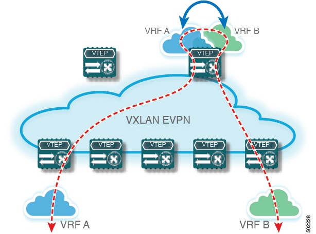
 Feedback