Provision SD-Access BGP EVPN Fabric Network

This section provides guidance on how to configure an SD-Access BGP EVPN fabric using Catalyst Center.

Cisco SD-Access solution

The Cisco SD-Access solution in Catalyst Center is based on intent-based networking principles and is used to automate wired and wireless campus networks. Cisco SD-Access provides visibility-based, automated end-to-end segmentation to separate user, device, and application traffic without redesigning the underlying physical network.

Setup options

The Cisco SD-Access solution supports two options to set up a fabric network based on the control plane architecture.

  • SD-Access LISP fabric network based on LISP for the control plane with the VXLAN (Virtual Extensible LAN) data plane.

  • SD-Access BGP EVPN fabric network based on BGP EVPN (Ethernet VPN) for the control plane with the VXLAN data plane.


Note


The SD-Access BGP EVPN fabric feature is in beta.


Related information

SD-Access BGP EVPN fabric network

A BGP EVPN fabric is a network segmentation solution within the Cisco SD-Access zero-trust solution. It supports a BGP EVPN control plane with a VXLAN data plane. The fabric leverages BGP to transport Layer 2 MAC and Layer 3 IP information.

BGP EVPN fabric roles

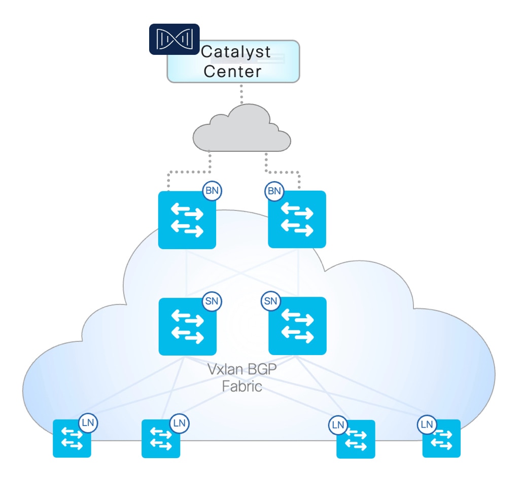
A BGP EVPN fabric supports spine, leaf, border, and border-spine roles—each offering unique functions within the fabric domain.

  • Spine: The distribution, core, or dedicated network switch that provides the Internal BGP (iBGP) Route-Reflector (RR) function.

  • Leaf: The Layer 3 access or distribution layer switch that connects to downstream endpoints.

  • Border: The EVPN fabric termination point at the network edge with upstream connection to the external domain network.

  • Border-Spine: The combined border and spine fabric role and function to support a small to mid-size collapsed core network design.


Note


The SD-Access BGP EVPN fabric feature is in beta.


SD-Access BGP EVPN topology

The figure shows an example of an SD-Access BGP EVPN fabric network with border, spine, and leaf nodes.

Figure 1. SD-Access BGP EVPN fabric network
SD-Access BGP EVPN Fabric

Product support matrix

An SD-Access BGP EVPN fabric is supported on Catalyst 9000 Series Switches running Cisco IOS XE 17.12.2 and later.

Product support for fabric roles

The table summarizes the supported Catalyst 9000 Series Switches and the fabric roles for an SD-Access BGP EVPN fabric.

Product Family Supported Role Recommended Role

Cisco Catalyst 9300 Series Switches

Leaf | Spine | Border

Leaf | Spine

Cisco Catalyst 9400 Series Switches

Leaf | Spine

Cisco Catalyst 9500 Series Switches

Leaf | Spine

Cisco Catalyst 9500H Series Switches

Leaf | Spine | Border

Cisco Catalyst 9600 Series Switches

Leaf | Spine | Border

Product deployment modes

An SD-Access BGP EVPN fabric supports automation and assurance capabilities for Catalyst 9000 Series Switches deployed in Standalone, StackWise, and StackWise Virtual modes.

The table summarizes the deployment modes and supported products.

Deployment Mode

Supported Products

Standalone

Cisco Catalyst 9300 Series Switches

Cisco Catalyst 9400 Series Switches

Cisco Catalyst 9400 Series Supervisor 1 Module

Cisco Catalyst 9400 Series Supervisor 2 Module

Cisco Catalyst 9500 Series Switches

Cisco Catalyst 9600 Series Supervisor 1 Module

StackWise

Cisco Catalyst 9300 Series Switches

Cisco Catalyst 9300L Series Switches

StackWise Virtual

Cisco Catalyst 9400 Series Supervisor 1 Module

Cisco Catalyst 9400 Series Supervisor 2 Module

Cisco Catalyst 9500 Series Switches

Cisco Catalyst 9600 Series Supervisor 1 Module

Automation support on SD-Access BGP EVPN fabric

The SD-Access BGP EVPN fabric supports these automation services:

  • Overlay IPv4 and IPv6 unicast

  • Layer 3 segmentation

  • Layer 3 segmentation with localized VLANs (Layer 3 only overlay)

  • Layer 2 segmentation with Anycast IRB

  • Layer 2 segmentation with ingress replication for broadcast, unknown unicast, and multicast (BUM) distribution

  • Layer 2 segmentation with multicast replication for BUM distribution

  • Overlay multicast service—Tenant Routed Multicast (TRM) with default and data MDT (Multicast Distribution Tree)

  • DHCP relay for IPv4 and IPv6

  • Border Layer 3 handoff with IPv4, IPv6, unicast, and multicast in VRF (Virtual Routing and Forwarding) lite mode

  • Border Layer 3 handoff with a prefix limit and aggregate route list

  • Dot1x and static host onboarding

SD-Access BGP EVPN fabric limitations

Product limitations

An SD-Access BGP EVPN fabric is not supported on

  • Cisco Catalyst 9200 Series Switches,

  • Cisco Catalyst 9300X Series Switches,

  • Cisco Catalyst 9500X Series Switches,

  • Cisco Catalyst 9600 Series Supervisor 2 Module (C9600X-SUP-2), and

  • Cisco Catalyst 9400 Series Supervisor 2 Module (C9400X-SUP-2).

Feature limitations

Currently, an SD-Access BGP EVPN fabric network has these limitations.

  • Catalyst Center does not support features, such as Role-based Access Control (RBAC) and Return Material Authorization (RMA), for fabric devices.

  • A single Catalyst Center deployment (physical or virtual) cannot support the coexistence of SD-Access BGP EVPN and SD-Access LISP-based fabric automation.

  • Fabric automation on Cisco Catalyst switches with preconfigured BGP peering is not supported.

  • Fabric automation based on external BGP (eBGP) is not supported.

  • Underlay multicast routing automation that is required for a Layer 2 overlay with multicast BUM replication and Layer 3 overlay multicast routing with TRM is not supported.

  • The network device can only associate to a single fabric device group. The flexible Layer 2 or Layer 3 overlay network automation can be associated with either a single device group, multiple device groups, or all device groups of a fabric site.

  • A single fabric site is limited to a single spine device group. The spine device group can peer with all the leaf and border nodes.

  • A Policy Extended Node (PEN) that automates downstream Layer 2 devices, such as switches, wireless controllers, Firewalls, and so on, is not supported.

  • A Layer 2 trunk configuration automation for connecting to downstream Layer 2 devices, such as switches, wireless controllers, Firewalls, and so on, is not supported.

  • The fabric resource pool can be configured only once during the initial fabric site configuration. Expanding or modifying the fabric resource pool after completing the fabric site automation is not supported.

  • A Layer 2 virtual network that uses a Layer 2 extension on spine, border, and border-spine network devices to perform an external Layer 2 handoff is not supported.

  • Wireless network automation and switch port for connecting to wireless controller and AP is not supported. Use alternate automation applications in Catalyst Center to perform such device automation.

  • Microsegmentation automation for wired and wireless overlay networks is not supported.

Set up an SD-Access BGP EVPN fabric

Follow these steps to deploy an SD-Access BGP EVPN fabric using Catalyst Center:


Note


Ensure that you have deleted all the existing SD-Access LISP fabric sites before you provision an SD-Access BGP EVPN fabric.


  1. Meet all prerequisites. See Prerequisites for Provisioning an SD-Access BGP EVPN Fabric.

  2. Enable the BGP EVPN protocol. See Enable BGP EVPN as the network segmentation protocol.

  3. Set up and manage the BGP EVPN fabric using these workflows.

    1. Create fabric sites and device groups.

    2. Create Layer 3 and Layer 2 virtual networks.

    3. Configure Layer 3 virtual network border features.

    4. Onboard an endpoint.

Prerequisites for Provisioning an SD-Access BGP EVPN Fabric

Prerequisites for provisioning an SD-Access BGP EVPN fabric using Catalyst Center:

  • Discover the devices in your network using their IP addresses and add them to the inventory. For more information, see Discover Your Network and Manage Your Inventory.

  • Define a geographical site hierarchy and the associated network settings. See Design the Network Hierarchy and Configure Network Settings.

  • Assign the devices to the geographical site and provision the devices with information about the device credentials, AAA server, DHCP server and DNS. You can add up to six IPv4 DHCP servers and one IPv6 DHCP server.

  • Enable IP routing in the underlay using LAN Automation or manual configuration. Ensure that there is IP reachability across the loopbacks of the devices.

  • Create and reserve IP address pools for VTEP fabric IP pool, Layer 2 virtual networks and border handoffs.

  • We recommend using multicast BUM replication in campus LAN networks, where each leaf node needs to replicate BUM copies efficiently to other leaf nodes in the network. The multicast BUM replication needs underlay multicast, which must be enabled as a prerequisite through LAN Automation or manual configuration.

  • Before provisioning a fabric, make sure that all devices are configured to VTP transparent mode.

  • Consider network pool sizing requirements while creating fabric sites and device groups for future compatibility.

    When setting up network pools, ensure that IPv4 pools are at least /16 and IPv6 pools are at least /112 sizes. While this is not strictly enforced right now, future updates will require these minimum sizes to ensure that the network can grow without running out of resources. If your current pools are smaller, you will have to delete and recreate the network with the correct sizes when you upgrade to the next version.

Enable BGP EVPN as the network segmentation protocol

You have the option of using LISP or BGP EVPN as the network segmentation protocol. Follow these steps to enable BGP EVPN as the SD-Access network segmentation protocol.

Procedure


Step 1

From the top-left corner, click the menu icon and choose Provision > Zero-Trust Overview.

Step 2

Under Explore and start your journey to SD-Access Zero-Trust Workplace, enable the required settings.

  1. For the Network Connectivity settings, enable With CAT9K to use Cisco Catalyst 9000 Series Switches or enable With Traffic Telemetry Appliance to use the Catalyst Center Traffic Telemetry Appliance in your zero-trust workplace journey.

  2. For the Services settings, enable the required options.

    • With ISE: Use Cisco Identity Services Engine in your zero-trust workplace journey.

    • With Talos: Use Talos Intelligence in your zero-trust workplace journey.

    • With CBAR Enabled: Use Controller-Based Application Recognition (CBAR) in your zero-trust workplace journey.

    • BGP EVPN: Switch to a BGP EVPN fabric.

  3. (Optional) Hover your cursor over each step around the journey map to view more details.

Step 3

Under I’m Done Exploring and Ready to Start My Journey, choose one of these options:

  • To create a fabric network and start your journey towards a zero-trust workplace, click Start my journey with creation of network fabric.

  • If you already have fabric network connectivity and want to start your journey towards zero-trust workplace with endpoint visibility, click I already have connectivity and want to start with Endpoint Visibility.

Step 4

Click Start My Journey.

Step 5

In the Modify Journey Map dialog box, do these steps:

  1. Review your journey map settings.

    Note

     
    • Catalyst Center displays a message if it doesn't discover the selected services for your network.

    • Catalyst Center displays a message if it discovers additional services that were not selected in the journey.

  2. (Optional) To remove a selected service from your journey map settings, uncheck the corresponding check box.

  3. Click Confirm.


Create fabric sites and device groups

A device group represents a particular role in the BGP EVPN fabric. You can group the devices under a device group, based on the role they perform. By default, Catalyst Center creates three device groups: border, leaf, and spine. You can replace the predefined device groups and add new custom device groups, which may be necessary if the network requires multiple leaf and border device groups for a virtual network deployment or if the border and spine nodes will be collocated.

You can create multiple leaf and border groups but only one spine or border spine group.

Follow these steps to create fabric sites and device groups.

Before you begin

Ensure that

Procedure


Step 1

From the main menu, choose Provision > Fabric Sites.

Step 2

Under the Fabric Sites tab, click Create Fabric Sites and Device Groups.

Step 3

In the Create Fabric Sites window, click Let’s Do it to start the workflow.

Step 4

In the Fabric Site Location window, choose a geographical location to deploy a BGP EVPN fabric.

Step 5

If you want to create more device groups apart from the default border, leaf, and spine device groups, follow these steps:

  1. In the Manage Device Groups window, click Create a Device Group

  2. In the Add a Device Group window, enter a name, choose the fabric role, and click Save.

You can delete a device group by clicking Actions > Delete Device Group(s) and clicking Confirm.

Step 6

In the Assign Devices to Device Groups window, choose one or more devices and click Assign Device Group.

Step 7

In the Assign Device Group window, choose a device group from the drop-down list and click Save.

Step 8

In the Specify Fabric Site Settings window, specify the attributes and resource pools for the fabric and click Next.

Note


Fabric site settings is a one-time provisioning step to build and manage the fabric within the given address range. After the site is provisioned, these settings can't be edited. We recommend sizing each address pool properly to accommodate future growth.

Attribute

Description

BGP Autonomous System Number (ASN) (Mandatory) Enter the BGP ASN for your network. Both 2-byte and 4-byte ASNs are supported.

VTEP Fabric IPv4 Pool

VTEP Fabric IPv6 Pool

(Optional) Choose the IP address pool from the drop-down list. The address from this IP pool is used to assign an IPv4 or IPv6 loopback interface for each Layer 3 virtual network. This IP address is used as the source IP address for DHCP Relay and PIM source-register to support TRM for each of the Layer 3 overlay networks.

Note


When setting up network pools, ensure that IPv4 and IPv6 pools are at least /16 and /112 sizes, respectively. This requirement is not strictly enforced yet, but it will be required in future to ensure that the network can grow without running out of resources. If your current pools are smaller, you will have to delete and recreate the network with the correct sizes when you upgrade to the next version.

See the restriction on network pool sizing in the Prerequisites for Provisioning an SD-Access BGP EVPN Fabric section.

Auto Core VLAN Range

(Optional) Displays the range of VLAN IDs for the autoassignment of VLAN IDs.

If you want to add a new range of VLAN IDs, enter a range.

A core VLAN ID from this range is assigned to each EVPN-enabled Layer 3 virtual network. You can also provision the core VLAN ID through the Layer 2 profile as a part of the Layer 3 virtual network creation workflow.

Note


The core VLAN ID will not be checked for conflicts on leaf and border systems, even if it overlaps with existing configurations. Therefore, it's important to ensure that the core VLAN ID is unique and falls within a reserved range. Do not use this ID for any other networking purpose.

Core VLANs Excluded from Auto Allocation

(Optional) Displays the range of VLAN IDs that are excluded from the autoallocation.

If you want to exclude specific VLAN IDs from the autoallocation, enter VLAN IDs. These VLAN IDs are not allocated as core VLAN ID.

Auto Default MDT Pool

(Optional) Enter a Multicast Distribution Tree (MDT) IP subnet address.

An IP address from this subnet is autoassigned as the underlay default MDT IP address for each Layer 3 virtual network that is enabled for overlay multicast service.

Auto Multicast BUM Replication Pool

(Optional) Enter a multicast IP subnet address. An IP address from this subnet is autoassigned as the multicast group IP address for each Layer 2 virtual network.

The multicast group IP address for a given Layer 2 virtual network is used to replicate the Layer 2 BUM traffic that is received from a source within the Layer 2 virtual network. This traffic is sent to all the VTEPs that are present in the Layer 2 virtual network overlay.

Auto VNI Range

(Optional) Displays the range of VXLAN network identifiers (VNIDs) for the autoassignment of VNI to Layer 2 and Layer 3 virtual networks.

If want to add a new range of VNIDs, enter a range. The Layer 2 VNID and Layer 3 VNID are unique within a fabric site.

VNIs Excluded from Auto Allocation

(Optional) Displays the VNIDs that are not assigned to a Layer 2 virtual network or Layer 3 virtual network automatically.

Enter a new VNID that you want to exclude.

Auto RD Format

(Optional) Displays the route distinguisher (RD) format used to generate an automatic RD for each Layer 2 virtual network and Layer 3 virtual network.

If you want to add an RD, choose a format from the drop-down list. Two formats are supported: IP:VLANID and IP:VNI. IP is the device Loopback0 IP address. The default RD format is IPv4 Address:VLAN ID.

Auto RT Format

(Optional) Displays the route target (RT) format used to generate an automatic RT for a Layer 2 virtual network and Layer 3 virtual network.

If you want to add an RT, choose a format from the drop-down list. Two formats are supported: ASN:VLANID and ASN:VNI. The default RT format is ASN:VLAN ID.

Step 9

In the Summary window, review the fabric site settings.

You can edit the settings for a fabric site or device groups.

Step 10

Schedule the task for deployment.

Depending on Visibility and Control of Configurations settings, you can either:

Note


The Scheduled Deployment, Submit for Approval, and ITSM Approval features are currently not supported in an SD-Access EVPN VXLAN fabric.

Step 11

On the Tasks window, monitor the task deployment.

Step 12

It takes a few seconds for the site and device groups to be provisioned. Upon successful creation, a success message is displayed and you can view the fabric site in the Fabric Sites window.


Edit fabric sites and device groups

Use this procedure to edit fabric sites and device groups.

Procedure


Step 1

From the top-left corner, click the menu icon and choose Provision > Fabric Sites.

Step 2

In the Fabric Sites tab, under SUMMARY, click the number that indicates the count of fabric sites.

Step 3

In the Fabric Sites window, choose a fabric site and hover your cursor over More Actions and click Edit Fabric Site.

Step 4

In the Modify Fabric Site window, click Let’s Do it to begin the modify workflow.

Step 5

To edit a device group, in the Manage Device Groups window, choose a device group and choose More Actions > Edit Device Group.

Note


You cannot edit or delete a device group that has devices assigned to it and is provisioned.

Step 6

In the Device Group Name field, enter a name and save the changes.

If you want to create more device groups apart from the default border, leaf, and spine device groups, click Create a Device Group. For more information, see Create fabric sites and device groups.

Step 7

Click Save and Next.

Step 8

In the Assign Devices to Device Groups window, choose a device that you want to assign to or unassign from the device group and click Assign Device Group or Unassign Device Group correspondingly. You can choose multiple devices.

Step 9

Click Save and Next.

Step 10

In the Specify Fabric Site Settings window, review the fabric attributes and fabric resource pools and click Next. For information on the attributes, see Create fabric sites and device groups.

Step 11

In the Summary window, review the fabric site settings and click Next.

You can edit the required settings from here.

Step 12

Schedule the task for deployment.

Depending on Visibility and Control of Configurations settings, you can either:

Note


The Scheduled Deployment, Submit for Approval, and ITSM Approval features are currently not supported in an SD-Access EVPN VXLAN fabric.

Step 13

On the Tasks window, monitor the task deployment.

It takes a few seconds for the site and device groups to be provisioned. When the site is modified successfully, a success message is displayed.


Delete fabric sites and device groups

Use this procedure to delete fabric sites and device groups.

Procedure


Step 1

From the top-left corner, click the menu icon and choose Provision > Fabric Sites.

Step 2

In the Fabric Sites tab, under SUMMARY, click the number that indicates the count of fabric sites.

Step 3

In the Fabric Sites window, choose a fabric site and hover your cursor over More Actions and click Delete Fabric Site.

Note


Ensure that all devices are unassigned from all the device groups before you delete the fabric.

Step 4

Click Confirm.

It takes a few seconds for the site and device groups to be unprovisioned and deleted. When the site is deleted successfully, a success message is displayed.


Create Layer 3 virtual networks

Use this procedure for Layer 3 segmentation (Layer 3 virtual network) for IPv4, IPv6, and multicast services in the overlay.

Before you begin

Ensure that you have created fabric sites and device groups before you provision a Layer 3 virtual network.

Procedure


Step 1

From the top-left corner, click the menu icon and choose Provision > Virtual Networks.

Step 2

In the Virtual Networks window, click Create Layer 3 Virtual Networks.

Step 3

In the Create Layer 3 Virtual Networks window, click Let’s Do it to go directly to the workflow.

Step 4

In the Layer 3 Virtual Networks window, follow these steps:

  1. Select a site from the Fabric Site drop-down list.

  2. In the Layer 3 Virtual Network name field, enter a name for the Layer 3 virtual network.

  3. To create multiple Layer 3 virtual networks, click the plus icon () and enter a name for the Layer 3 virtual network.

    You can add up to five Layer 3 virtual networks.

Step 5

In the Select Target Device Groups window, select the target device groups (leaf, border or both) for each Layer 3 virtual network and click Next.

You can select multiple leaf and border device groups based on where you want to deploy each Layer 3 virtual network. The SD-Access BGP EVPN fabric supports selective deployment of virtual networks.

Step 6

In the Specify L3 Virtual Networks Settings window, review the default values for the attributes under the Advanced Settings tab.

You can override the default settings and configure the attributes as per the requirements of your network.

This table describes the Layer 3 virtual network attributes.

Attribute

Description

Layer 3 VNI

(Mandatory) Specifies the Layer 3 VXLAN Network identifier (VNI).

Export IPV4 Route Target

(Optional) Specifies the Layer 3 route target (RT) for IPv4.

If the field is set to auto, the export RT is autogenerated in the predefined format. The format for RT is set during the fabric creation.

Import IPV4 Route Target

(Optional) Specifies the Layer 3 import route target for IPv4.

If the field is set to auto, the export RT is autogenerated in the predefined format. The format for RT is set during the fabric creation.

Export IPV6 Route Target

(Optional) Specifies the Layer 3 export route target for IPv6.

If the field is set to auto, the export RT is autogenerated in the predefined format. The format for RT is set during the fabric creation.

Import IPV6 Route Target

(Optional) Specifies the Layer 3 import route target for IPv6.

If the field is set to auto, the export RT is autogenerated in the predefined format. The format for RT is set during the fabric creation.

Step 7

(Optional) In the Specify L3 Virtual Networks Settings window, set up IPv4 or IPv6 tenant routed multicast (TRM) under the Multicast tab.

  1. Enable the Multicast toggle button to set up overlay multicast service for each Layer 3 virtual network.

  2. Use the toggle buttons to enable only IPV4 or both IPV4 and IPV6.

  3. From the RP Type drop-down list, choose the RP type.

    • Anycast: If you choose Anycast, RP is deployed on all leaf and border VTEPs in a Layer 3 virtual network.

    • Internal: If you choose Internal, you must specify a VTEP device (leaf or border), where the RP is to be deployed. From the Internal RP drop-down list, choose an internal RP.

    • External: If you choose External, it means that the RP is outside the fabric, not on any fabric VTEP. Ensure that the network fabric can connect to the external RP through a border interconnect.

      • RP IPV4: Enter the RP IPv4 address.

      • RP IPV6: Enter the RP IPv6 address.

  4. Choose the MDT mode: Default MDT or Data.

    If you choose Data, enter the values for Data MDT Group Range and Threshold.

Step 8

Click Next.

Step 9

In the Summary window, review the Layer 3 virtual network settings.

You can edit any Layer 3 virtual network settings here.

Step 10

Schedule the task for deployment.

Depending on Visibility and Control of Configurations settings, you can either:

Note


The Scheduled Deployment, Submit for Approval, and ITSM Approval features are currently not supported in an SD-Access EVPN VXLAN fabric.

Step 11

On the Tasks window, monitor the task deployment.

It takes a few seconds for the Layer 3 virtual network to be provisioned. After successful provisioning, a success message is displayed.


Edit Layer 3 virtual networks

This workflow enables editing the Layer 3 segmentation (Layer 3 virtual network) for IPv4, IPv6, and multicast services in the overlay.

Procedure


Step 1

From the top-left corner, click the menu icon and choose Provision > Virtual Networks.

Step 2

In the Virtual Networks window, under SUMMARY, click the number that indicates the count of Layer 3 virtual networks.

Step 3

In the Layer 3 Virtual Networks window, choose a Layer 3 virtual network and hover your cursor over More Actions and click Edit L3 Virtual Network.

Step 4

In the Modify Layer 3 Virtual Networks window, click Let’s Do it to go directly to the workflow.

You can edit the target device groups and multicast configurations for the Layer 3 virtual network.

Step 5

In the Select Target Device Groups window, choose the target device groups (leaf, border or both) for each Layer 3 virtual network as required.

You can choose multiple leaf and border device groups based on where you want to deploy each Layer 3 virtual network. The SD-Access EVPN fabric supports selective deployment of VNs.

Step 6

(Optional) In the Specify L3 Virtual Networks window, set up IPv4 or IPv6 tenant routed multicast (TRM) by updating the attributes under the Multicast tab.

  1. Enable the Multicast toggle button to set up overlay multicast service for each Layer 3 virtual network.

  2. Enable either IPV4 or both IPV4 and IPV6 toggle buttons.

  3. From the RP Type drop-down list, choose the RP type.

    • Anycast: If you choose Anycast, RP is deployed on all leaf and border VTEPs in a Layer 3 virtual network.

    • Internal: If you choose Internal, you must specify a VTEP device (leaf or border), where the RP is to be deployed. From the Internal RP drop-down list, choose an internal RP.

    • External: If you choose External, it means that the RP is outside the fabric, not on any fabric VTEP. Ensure that the network fabric can connect to the external RP through a border interconnect.

      • RP IPV4: Enter the RP IPv4 address.

      • RP IPV6: Enter the RP IPv6 address.

  4. Choose the MDT mode: Default MDT or Data.

    If you choose Data, enter Data MDT Group Range and Threshold.

Step 7

Review the Layer 3 virtual network settings in the Summary window.

You can edit the Layer 3 virtual network settings here.

Step 8

Schedule the task for deployment.

Depending on Visibility and Control of Configurations settings, you can either:

Note


The Scheduled Deployment, Submit for Approval, and ITSM Approval features are currently not supported in an SD-Access EVPN VXLAN fabric.

Step 9

On the Tasks window, monitor the task deployment.

It takes a few seconds for the Layer 3 virtual network to be provisioned. After successful provisioning, a success message is displayed.


Delete Layer 3 virtual networks

Use this procedure to delete the Layer 3 virtual networks.

Before you begin

You must delete all the associated Layer 2 virtual networks before deleting a Layer 3 virtual network.

Procedure


Step 1

From the top-left corner, click the menu icon and choose Provision > Virtual Networks.

Step 2

In the Virtual Networks tab, under Summary, click the number that indicates the count of layer 3 virtual networks.

Step 3

In the Layer 3 Virtual Networks window, choose a Layer 3 virtual network, hover your cursor over More Actions, and click Delete Layer 3 Virtual Network.

Step 4

In the Warning window, click Confirm.

Step 5

Schedule the task for deployment.

Depending on Visibility and Control of Configurations settings, you can either:

Note


The Scheduled Deployment, Submit for Approval, and ITSM Approval features are currently not supported in an SD-Access EVPN VXLAN fabric.

Step 6

On the Tasks window, monitor the task deployment.


Create Layer 2 virtual networks

Use this procedure to provision a Layer 2 virtual network across the leaf device groups.

Before you begin

Ensure that you have created a fabric site and a Layer 3 virtual network to deploy the Layer 2 virtual network.

Procedure


Step 1

From the top-left corner, click the menu icon and choose Provision > Virtual Networks.

Step 2

In the Virtual Networks window, click Create Layer 2 Virtual Networks.

Step 3

In the Create Layer 2 Virtual Networks window, click Let’s Do it to go begin the workflow.

Step 4

In the Layer 2 Virtual Networks window, configure these fields:

  • Choose a site from the Fabric Site drop-down list.

  • Provide a name in the Layer 2 Virtual Networks field.

  • Choose a virtual network from the Layer 3 Virtual Network drop-down to provision the Layer 2 virtual network.

  • Choose a gateway type: Anycast or Localized.

    • If you choose Anycast, the anycast gateway is deployed on all VXLAN Tunnel Endpoints (VTEPs) in the target device groups Layer 2 virtual network with Ethernet VPN (EVPN) and Integrated Routing and Bridging (IRB) services.

    • If you choose Localized, the localized gateway is configured on a single VTEP.

  • (Optional) Click the plus icon () to create multiple Layer 2 virtual networks. You can create up to five Layer 2 virtual networks in a single workflow.

Step 5

If you chose Anycast gateway, in the Select Target Device Groups window, choose the leaf device groups for the Layer 2 virtual network.

Step 6

If you chose Localised gateway, in the Select Target Device window, choose the devices for the Layer 2 virtual network.

Step 7

In the Specify L2 Virtual Network Settings window, review the default values of the Layer 2 virtual network attributes.

Optionally, you can change the values of these attributes. The attributes are a smaller subset for localized gateway Layer 2 virtual network.

This table describes the Layer 2 virtual network attributes.

Attribute

Description

VLAN ID

(Mandatory) Specifies the VLAN ID that is provisioned for the Layer 2 virtual network.

You can choose the VLAN ID from the drop-down list or create a VLAN using the Create New option.

Layer 2 VNI

(Mandatory) Specifies the Layer 2 VXLAN Network identifier (VNI). This field is set to auto by default.

Export RT

(Mandatory) Specifies the Layer 2 export route target (RT).

If the field is set to auto, the export RT is autogenerated in the predefined format. The format for RT is set during the fabric creation and is set to auto by default.

Import RT

(Mandatory) Specifies the Layer 2 import route target (RT).

If the field is set to auto, the import RT is autogenerated in the predefined format. The format for RT is set during the fabric creation and is set to auto by default.

Replication Mode

(Optional) Specifies the replication mode for multicast traffic. Choose between Ingress Replication or Multicast.

By default, ingress replication mode is enabled.

BUM Multicast Group

(Optional) Specifies the IP address for the Multicast mode of replication. This option is available only if you choose Multicast mode of replication.

IPV4 Pool

(Mandatory) Specifies an IPv4 address pool for the Layer 2 virtual network. Choose an IPv4 subnet pool from the drop-down list.

DHCPV4 Relay

(Optional) To configure a DHCP Relay in IPv4 service, enable the DHCPV4 Relay toggle button and provide the IPv4 address and VRF for the DHCP server.

You can add up to six IPv4 DHCP servers with the same VRF.

IPV6 Pool

(Optional) Specifies an IPv6 address pool for a Layer 2 virtual network. Choose an IPv6 subnet pool from the drop-down list.

DHCPV6 Relay

To configure a DHCP Relay in IPv6 service, enable the DHCPV6 Relay toggle button and provide the IPv6 address and VRF for the DHCPv6 server.

You can add only one IPv6 DHCP server.

Step 8

In the Summary window, review the Layer 2 virtual network settings. Edit the settings, if necessary.

Step 9

Schedule the task for deployment.

Depending on Visibility and Control of Configurations settings, you can either:

Note


The Scheduled Deployment, Submit for Approval, and ITSM Approval features are currently not supported in an SD-Access EVPN VXLAN fabric.

Step 10

On the Tasks window, monitor the task deployment.

It takes a few seconds for the Layer 2 virtual network to be provisioned. After successful provisioning, a success message is displayed.


Edit Layer 2 virtual networks

Use this procedure to edit the Layer 2 virtual network settings.

Before you begin

Ensure that you have created

  • a fabric site, and

  • a Layer 3 and Layer 2 virtual network.

Procedure


Step 1

From the top-left corner, click the menu icon and choose Provision > Virtual Networks.

Step 2

In the Virtual Networks window, under SUMMARY, click the number that indicates the count of Layer 2 virtual networks.

Step 3

In the Layer 2 Virtual Networks window, choose the virtual network, hover your cursor over More Actions, and click Edit Layer 2 Virtual Network.

Step 4

In the Modify Layer 2 Virtual Networks window, click Let’s Do it to go directly to the workflow.

You can edit the target device groups and some of the Layer 2 virtual network configurations.

Step 5

In the Select Target Device or Select Target Device Groups window, choose the devices or device groups for the Layer 2 virtual network as required.

Step 6

In the Specify L2 Virtual Network Settings window, edit these attributes as required.

Attribute

Description

Replication Mode

(Optional) Specifies the replication mode for multicast traffic. Choose between Ingress Replication or Multicast.

By default, ingress replication mode is enabled.

BUM Multicast Group

(Optional) Specifies the IP address for the Multicast mode of replication. This option is available only if you choose Multicast mode of replication.

DHCPV4 Relay

(Optional) To configure a DHCP Relay in IPv4 service, enable the DHCPV4 Relay toggle button and provide the IPv4 address and VRF for the DHCP server.

You can add up to six IPv4 DHCP servers with the same VRF.

DHCPV6 Relay

(Optional) To configure a DHCP Relay in IPv6 service, enable the DHCPV6 Relay toggle button and provide the IPv6 address and VRF for the DHCPv6 server.

You can add only one IPv6 DHCP server.

Step 7

In the Summary window, review the Layer 2 virtual network settings. Edit the settings, if necessary.

Step 8

Schedule the task for deployment.

Depending on Visibility and Control of Configurations settings, you can either:

Note


The Scheduled Deployment, Submit for Approval, and ITSM Approval features are currently not supported in an SD-Access EVPN VXLAN fabric.

Step 9

On the Tasks window, monitor the task deployment.

It takes a few seconds for the Layer 2 virtual network to be provisioned. After successful provisioning, a success message is displayed.


Delete Layer 2 virtual networks

Use this procedure to delete a Layer 2 virtual network across the leaf device groups.

Procedure


Step 1

From the top-left corner, click the menu icon and choose Provision > Virtual Networks.

Step 2

In the Virtual Networks tab, under Summary, click the number that indicates the count of Layer 2 virtual networks.

Step 3

In the Layer 2 Virtual Networks window, choose a Layer 2 virtual network, hover your cursor over More Actions, and click Delete Layer 2 Virtual Network.

Step 4

In the Warning window, click Confirm.

Step 5

Schedule the task for deployment.

Depending on Visibility and Control of Configurations settings, you can either:

Note


The Scheduled Deployment, Submit for Approval, and ITSM Approval features are currently not supported in an SD-Access EVPN VXLAN fabric.

Step 6

On the Tasks window, monitor the task deployment.


Create border Layer 3 virtual network features

This workflow provisions border features like external handoffs on the Layer 3 virtual network.


Note


The options to provision DHCP relay on the SVI handoff interface and provision handoff interface without BGP peering are being deprecated from this workflow. These options will be enabled through Layer 2 virtual network workflow on border leafs in the future release. It is recommended not use these options in the current workflow to ease future migrations.


Before you begin

Ensure that you have already created fabric sites, device groups, and Layer 3 virtual networks before you provision Layer 3 virtual network features on a border device group.

Procedure


Step 1

From the top-left corner, click the menu icon and choose Provision > Virtual Networks.

Step 2

Use one of these options:

  • In the Virtual Networks window, click Create Border L3VN Features.

  • In the Layer 3 Virtual Networks window, choose a Layer 3 virtual network, hover your cursor over More Actions, and click Edit L3 Virtual Network..

Step 3

In the Create Border L3VN Features window, click Let’s Do it to begin the workflow.

Step 4

In the Select Layer 3 Virtual Networks window, choose a site from the Fabric Site drop-down list and choose the Layer 3 virtual networks for border deployment.

Step 5

In the Select Border Device Groups window, choose a border device group for each Layer 3 virtual network.

Note


Before you set up border services like handoffs in a device group, you must first deploy the Layer 3 virtual network in that group using the Layer 3 virtual network workflow. If the Layer 3 virtual network is not already deployed in a device group, that group will not appear as an option in the border Layer 3 virtual network setup process.

Step 6

In the Configure Border Handoff window, configure the border handoff attributes.

Optionally, you can configure an external Layer 3 handoff for each Layer 3 virtual network.

Attribute

Description

Border Handoff

Click the Border Handoff toggle button to enable border handoff. Border handoff is disabled by default.

Device

Choose a border device from the drop-down list.

Layer 3 Interface Type

Choose the Layer 3 interface type for the external virtual network handoff.

Options: L3 Sub Interface, SVI

Port

Choose a port on the device from the drop-down list, depending on the type of interface chosen.

Dot1q Tag

Enter the VLAN ID for the chosen interface.

IPV4 Pool and

IPV4 Address

Choose an IPv4 address pool from the IPV4 Pool drop-down list. Subsequently, enter an IP address in the IPV4 Address field. This is the IP address for the handoff interface.

IPV6 Pool and

IPV6 Address

(Optional) Choose and IPv6 address pool from the IPV6 Pool drop-down list and enter an IPv6 address for the handoff interface.

BGP Peers

(Optional) Click the BGP Peers toggle button to enable BGP peering on the handoff interface.

If you enable BGP peering, enter the IPv4 address, IPv6 address, and ASN of the external peer interface that is connected to the Layer 3 VRF interface.

Multicast

(Optional) Click the Multicast toggle button to enable multicast on the handoff interface of the border devices within the border device group.

Step 7

(Optional) In the Specify Border Settings window, you can configure the aggregate route list and prefix limit.

  • In Aggregate Route List section, enter the IPv4 or IPv6 subnets that are to be advertised to all virtual network peering sessions on a given border device.

  • In the Prefix Limit section, enter the maximum number of external routes that can be advertised in the fabric.

Step 8

In the Summary window, review the border settings.

You can edit any border settings displayed on this window.

Step 9

Schedule the task for deployment.

Depending on Visibility and Control of Configurations settings, you can either:

Note


The Scheduled Deployment, Submit for Approval, and ITSM Approval features are currently not supported in an SD-Access EVPN VXLAN fabric.

Step 10

On the Tasks window, monitor the task deployment.

It takes a few seconds for the border features to be provisioned. After successful provisioning, a success message is displayed.


Edit border Layer 3 virtual network features

Use this procedure to edit the border features configured on the Layer 3 virtual network.


Note


The options to provision DHCP relay on the SVI handoff interface and provision handoff interface without BGP peering are being deprecated from this workflow. These options will be enabled through Layer 2 virtual network workflow on border leafs in the future release. It is recommended not use these options in the current workflow to ease future migrations.


Before you begin

Ensure that you have configured the border features in your Layer 3 virtual network.

Procedure


Step 1

From the top-left corner, click the menu icon and choose Provision > Virtual Networks.

Step 2

In the Layer 3 Virtual Networks window, choose a Layer 3 virtual network, hover your cursor over More Actions, and click Modify Border L3VN Features.

Step 3

In the Modify Border L3VN Features window, click Let’s Do it to begin the workflow.

You can edit the border device groups, enable or disable the border handoff and edit some of the border handoff configurations.

Step 4

In the Select Border Device Groups window, choose a border device group for the Layer 3 virtual network, as required.

Step 5

In the Configure Border Handoff window, edit the border handoff attributes as required.

Attribute

Description

Border Handoff

Click the Border Handoff toggle button to enable border handoff.

IPV4 Pool and

IPV4 Address

Choose an IPv4 address pool from the IPV4 Pool drop-down list. Subsequently, enter an IP address in the IPV4 Address field. This is the IP address for the handoff interface. You cannot edit the IP address if it already exits.

IPV6 Pool and

IPV6 Address

(Optional) Choose and IPv6 address pool from the IPV6 Pool drop-down list and enter an IPv6 address for the handoff interface. You cannot edit the IP address if it already exits.

BGP Peers

(Optional) Click the BGP Peers toggle button to enable BGP peering on the handoff interface.

If you enable BGP peering, enter the IPv4 address, IPv6 address, and ASN of the external peer interface that is connected to the Layer 3 VRF interface.

Multicast

(Optional) Click the Multicast toggle button to enable multicast on the handoff interface of the border devices within the border device group.

Step 6

(Optional) In the Specify Border Settings window, you can edit the aggregate route list and prefix limit.

  • In Aggregate Route List section, enter the IPv4 or IPv6 subnets that are to be advertised to all virtual network peering sessions on a given border device.

  • In the Prefix Limit section, enter the maximum number of external routes that can be advertised in the fabric.

Step 7

In the Summary window, review the border settings.

You can edit the border settings as required.

Step 8

Schedule the task for deployment.

Depending on Visibility and Control of Configurations settings, you can either:

Note


The Scheduled Deployment, Submit for Approval, and ITSM Approval features are currently not supported in an SD-Access EVPN VXLAN fabric.

Step 9

On the Tasks window, monitor the task deployment.

It takes a few seconds for the border features to be provisioned. After successful provisioning, a success message is displayed.


Delete border Layer 3 virtual network features

Use this procedure to delete the Layer 3 virtual network features on the border device group.

Procedure


Step 1

From the top-left corner, click the menu icon and choose Provision > Virtual Networks.

Step 2

In the Virtual Networks tab, under Summary, click the number that indicates the count of Layer 3 virtual networks.

Step 3

In the Layer 3 Virtual Networks window, choose a Layer 3 virtual network, hover your cursor over More Actions, and click Delete Border L3VN Features.

Step 4

In the Warning window, click Confirm.

Step 5

Schedule the task for deployment.

Depending on Visibility and Control of Configurations settings, you can either:

Note


The Scheduled Deployment, Submit for Approval, and ITSM Approval features are currently not supported in an SD-Access EVPN VXLAN fabric.

Step 6

On the Tasks window, monitor the task deployment.


Onboard an endpoint

Onboard an endpoint into the fabric by attaching the endpoint to a fabric device group. To onboard an endpoint, it has to be successfully authenticated, authorized, and assigned to a virtual network. However, the authentication process is not mandatory. Devices can be onboarded without 802.1X Authentication template.

Use an Authentication Template to apply the authentication process on the port of the fabric device group devices. You can select an authentication template and port configurations through the Create/Edit Network Profile workflow for the device group. Use the Provision Network Profile workflow on the fabric device group to apply the selected authentication template and the port configurations.

Edit a Layer 2 network profile

Use this procedure to edit the Layer 2 network profile attributes for a device group.

Procedure


Step 1

From the top-left corner, click the menu icon and choose Provision > Fabric Sites.

Step 2

In the Fabric Sites tab, under SUMMARY, click the number that indicates the count of fabric sites.

Step 3

In the Fabric Sites window, click a fabric site.

Step 4

In the Device Groups tab, choose a fabric device group, hover your cursor over More Actions, and click Create/Edit Network Profiles.

Step 5

In the Edit Network Profile window, configure the network profile attributes displayed in the left pane.

All the configurations are optional. You can use the Reset or Set to Default options to reset the configured values or restore the default values.

To configure additional configurations, click Add Configurations in the respective configuration window and choose the required attribute or click Add All.

Table 1. VTP

Attribute

Description

Mode

Choose a VTP mode in the drop-down list.

VTP mode options: Off, Server, Client, and Transparent.

Table 2. Authentication

Attribute

Description

802.1x

Choose an option for the authentication method: Enabled, Disabled, or None.

Authentication Template

Click Add Authentication Template and choose an authentication template from the drop-down list.

Table 3. Port Configuration

Attribute

Description

Port Configuration Name

Enter a name for the port configuration.

Switchport

Description

Enter a description for the switchport interface.

Mode

Choose the administrative mode for the interface from the drop-down list: Access, Trunk, Dynamic Auto, Dynamic Desirable, 802.1Q Tunnel.

Access VLAN ID

Choose an access VLAN ID from the drop-down list.

Voice VLAN ID

Choose a VLAN ID for the voice traffic from the drop-down list.

Admin Status

Choose an interface status from the drop-down list: Enabled or Disabled.

Allowed VLANs

(Additional Configuration) Specify the list of allowed VLANs on the trunk.

Native VLAN ID

(Additional Configuration) Choose the native VLAN ID from the drop-down list.

Interface Template

Auth Template

(Additional Configuration) Choose an authentication template name from the drop-down list.

Step 6

In the Review Summary window, review the network profile.

You can edit the network profile settings here.

Step 7

Click Save.


Attach a Layer 2 network profile

Use this procedure to attach a Layer 2 network profile to a device group.


Note


The Attach Layer 2 Network Profile option is being deprecated.


Before you begin

Ensure that you have created Layer 2 network profiles.

Procedure


Step 1

From the top-left corner, click the menu icon and choose Provision > Fabric Sites.

Step 2

In the Fabric Sites tab, under SUMMARY, click the number that indicates the count of fabric sites.

Step 3

In the Fabric Sites window, click a fabric site.

Step 4

In the Device Groups tab, choose a fabric device group, hover your cursor over More Actions, and click Attach Layer 2 Network Profile.

Step 5

Choose a Layer 2 network profile from the network profile list and click Attach.


Provision a network profile

Follow these steps to provision a device group with the attached network profiles.

Procedure


Step 1

From the top-left corner, click the menu icon and choose Provision > Fabric Sites.

Step 2

In the Fabric Sites tab, under SUMMARY, click the number that indicates the count of fabric sites.

Step 3

In the Fabric Sites window, click a fabric site.

Step 4

In the Device Groups tab, choose a fabric device group, hover your cursor over More Actions, and click Provision Network Profile.

Step 5

The Network Profiles Overview window displays the profiles that are ready to be deployed.

Step 6

Click Next.

Step 7

In the Layer 2 - Port Configuration window, choose a device from the left pane and select its interfaces to apply the configurations. Click Assign.

Step 8

In the Assign Configuration window, choose a port from the Port Configuration Name drop-down list and click Assign.

Step 9

Schedule the task for deployment.

Depending on Visibility and Control of Configurations settings, you can either:

Note


The Scheduled Deployment, Submit for Approval, and ITSM Approval features are currently not supported in an SD-Access EVPN VXLAN fabric.

Step 10

On the Tasks window, monitor the task deployment.