Design the Network Hierarchy

Network hierarchy overview

You can create a network hierarchy that represents the geographical locations of your network.

Structure of a network hierarchy
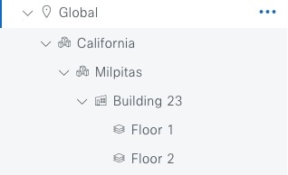
The network hierarchy is organized in a hierarchical structure. This hierarchy consists of sites. A site may refer to an area, building, or floor. The placement of each site in the hierarchical structure depends on network hierarchy rules. See this figure and table to learn how you can structure different sites in your network hierarchy.

Figure 1. Network hierarchy
The network hierarchy consists of Global (the default site element), California (an area), Milpitas (an area), Building 23, Floor 1, and Floor 2.
Table 1. Network hierarchy elements

Site types

Description

Rule

Global ()

The default site element under which all other site elements reside.

Only areas and buildings can reside directly under Global.

Areas (Site and area icon in network hierarchy tree)

Areas identify a geographic region. They provide a way to group areas, buildings, or both areas or buildings. Therefore, they do not have a physical address.

Areas can reside directly under Global or other areas.

Buildings (Buildings icon in network hierarchy tree)

Buildings can have physical addresses or latitude and longitude coordinates.

Buildings can reside directly under Global or areas. They cannot contain areas, but they can contain floors.

Floors (Floor icon in network hierarchy tree)

Floors can be added to buildings with or without maps that contain various building components, like walls and windows.

Floor maps allow you to visualize the wireless network coverage of your wireless devices positioning on the floor. You can manually create them or import them from files, such as DXF, DWG, JPG, GIF, PNG, or PDF file types.

Only floors reside under buildings.

Note

 
  • You can't move an existing floor to a different building.

  • You can change the site hierarchy for unprovisioned devices while preserving AP locations on floor maps.

Apply design settings to a site

The hierarchical organization of the network hierarchy allows you to easily apply design settings or configurations to a specific hierarchical site. For example, you can apply design settings to an entire area or to only a floor.


Tip


Naming hierarchical sites can help you identify where to apply design settings later.


Build your network hierarchy

To get started, build your network hierarchy using one of these methods:

Design a new network hierarchy

The Design area is where you create the structure and framework of your network, including the physical topology, network settings, and device type profiles that you can apply to devices throughout your network. Use the Design workflow if you do not already have an existing infrastructure. If you have an existing infrastructure, use the Discovery feature. For more information, see Discovery overview.

You can perform these tasks in the Design area:

Procedure


Step 1

Create your network hierarchy. For more information, see Create, edit, and delete a site.

Step 2

Define global network settings. For more information, see Network settings overview.

Step 3

Define network profiles. For more information, see Network profiles overview.


Use an existing Cisco network hierarchy

If you have an existing network hierarchy in Cisco Prime Infrastructure, you can export it and then import it into Catalyst Center, saving time and effort spent in creating a new network hierarchy.

This information is available for you to re-create your network hierarchy:

  • Site Hierarchy: Your existing site hierarchy is downloaded in a CSV file format. The CSV file contains details such as site names, parent hierarchy, number of floors, location, and site address.

  • Map Archive: Map information is downloaded as a map archive in a TAR file format. The map archive file contains data such as the date and time, number of floors, and APs. Depending on what you decide to download, the map archive can also include map information, such as floor dimensions (length, width, and height) and details about the APs and overlay objects that have been placed on the floor maps. You can also decide to download calibration information, such as the RF attenuation model that has been applied to each floor.

    To base the map archive on the global hierarchy or the hierarchy of a single site, building, or floor:

    • Site: The chosen site and all of its subsites, buildings, and floors are exported.

    • Building: The chosen building and all of its floors are exported.

    • Floor: The chosen floor is exported.


    Note


    Catalyst Center supports the United States' Federal Information Processing Standards (FIPS). FIPS is an optional mode that can be enabled when installing the Catalyst Center image. By default, FIPS mode is disabled.


    FIPS mode has an impact on the export and import of map archives.

    If FIPS mode is enabled:

    • Exported map archives are unencrypted.

    • Only unencrypted map archives can be imported.

    If FIPS mode is disabled:

    • Exported map archives are encrypted.

    • Both encrypted and unencrypted map archives can be imported.

Export your site hierarchy from Cisco Prime Infrastructure

You can export your site hierarchy from Cisco Prime Infrastructure in a CSV file format. The CSV file contains details such as site names, parent hierarchy, number of floors, location, and site address.

Site hierarchy export is supported in Cisco Prime Infrastructure, Release 3.2 and later.

Procedure


Step 1

In Cisco Prime Infrastructure, choose Inventory > Group Management > Network Device Groups.

Step 2

In the Device Groups window, click Export Groups.

Step 3

In the Export Groups dialog box, click the APIC-EM radio button.

Step 4

To download the CSV file, click OK.


Export your map archive from Cisco Prime Infrastructure

You can export map archive files from Cisco Prime Infrastructure and import them into Catalyst Center. Map archives contain map information, such as floor dimensions, and calibration information, such as the Radio Frequency (RF) attenuation model that has been applied to each floor in Cisco Prime Infrastructure.

Procedure


Step 1

From the Cisco Prime Infrastructure GUI, choose Maps > Wireless Maps > Site Maps (New).

Step 2

From the Export drop-down list, select Map Archive.

The Export Map Archive window opens, and the Select Sites window opens by default.

Step 3

Check the check box adjacent to a specific site, campus, building, or floor that you want to export. Alternatively, check the Select All check box to export all the maps.

Step 4

Select at least one of these options:

  • Map Information: Click the On button to export floor dimensions (length, width, and height) and details about the APs and overlay objects that have been placed on the floor maps.

  • Calibration Information: Click the On button to export the RF attenuation model that has been applied to each floor. It is a good practice to export the existing calibration data from Cisco Prime Infrastructure. Otherwise, you must re-enter the calibration details manually.

    If you select to include calibration information, you also need to specify whether to include information for the selected maps or all the information.

    • Calibration Information for selected maps: Calibration information for the selected site maps is exported.

    • All Calibration Information: Calibration information for the selected map and any additional calibration information that is available in the system is exported.

Step 5

Click Generate Map Archive.

This message shows the progress of the operation:

Exporting data is in progress

A TAR file is created and is saved to your local machine.

Step 6

Click Done.


Import your site hierarchy to Catalyst Center

You can import a site hierarchy that you exported from Cisco Prime Infrastructure as a CSV file. For information about exporting the site hierarchy, see Export your site hierarchy from Cisco Prime Infrastructure.

Before you begin

  • Make sure that you have Cisco Wireless Controllers and APs in your Catalyst Center inventory. If not, discover them using the Discovery feature.

  • Add and position APs on a floor map.

  • If you manually created sites in Catalyst Center that are present in Cisco Prime Infrastructure, you must remove them from Catalyst Center before you can import them.

Procedure


Step 1

From the main menu, choose Design > Network Hierarchy.

Step 2

From the map toolbar, click Import and select Import Sites.

Step 3

In the dialog box, click one of these radio buttons:

  • Merge with Existing Sites: The downloaded site information is combined with the existing site information.

  • Overwrite Existing Sites: If the same site already exists in Catalyst Center, the existing site information is overwritten with the downloaded site information.

Step 4

In the dialog box, drag and drop your CSV file into the download area. Alternatively, you can click Choose a file, navigate to where your CSV file is located, and then click Import.

Note


If you do not have a CSV file, click CSV template to download a CSV file that you can edit and upload.


Import your map archive to Catalyst Center

You can import a map archive TAR file into Catalyst Center. For example, you can upload the TAR file that you exported from Cisco Prime Infrastructure.


Note


Catalyst Center supports the United States' Federal Information Processing Standards (FIPS). FIPS is an optional mode that can be enabled when installing the Catalyst Center image. By default, FIPS mode is disabled.


For information about exporting site hierarchy, see Export your map archive from Cisco Prime Infrastructure.

Procedure


Step 1

From the main menu, choose Design > Network Hierarchy.

Step 2

From the map toolbar, click Import and select Import Floor Maps.

Step 3

In the Import Floor Maps dialog box, drag and drop the map archive file.

Step 4

Click Import.

The map archive file is imported.


Use an existing Ekahau network hierarchy

The Ekahau Pro tool allows you to create a complete network plan for your enterprise, including floor layout, AP locations, and obstacles. After creating the floor layout, you can export the simulated network plan as an Ekahau project file. You can also export the real-world site survey data into a format that Catalyst Center can use.

Export the Ekahau project from Catalyst Center

To augment the preconfigured working floors, the Catalyst Center allows you to export the working floors from Catalyst Center as an Ekahau project and import the project into the Ekahau Pro Tool.

Procedure


Step 1

From the main menu, choose Design > Network Hierarchy.

A world map displays in the right pane.

Step 2

In the left pane, select the desired site, building, or floor.

Step 3

To export a complete network map as an Ekahau project, from the Export drop-down list, select Export Floor Maps.

To export an Ekahau project of a site, building, or floor map, from the left pane, hover your cursor over the ellipsis next to the desired site, building, or floor and select Export Floor Maps.

The Export Floor Maps dialog box is displayed.

Step 4

In the Export Floor Maps dialog box, select the Ekahau Project export format.

Step 5

Click Export.

An ESX file is created and saved to your local machine.

Step 6

Import the ESX file into the Ekahau Pro tool, augment the floor, and save the file.

Step 7

Import the Ekahau project into the Catalyst Center under the site. For more information, see Import an Ekahau project to Catalyst Center.


Import an Ekahau project to Catalyst Center

Before you begin

Importing an Ekahau Cloud project can fail if the project has local changes (such as removing an AP or wall), that are out-of-sync with the Ekahau Cloud project. To avoid this situation, make sure to synchronize any local changes to the Ekahau Cloud before importing the Ekahau Cloud project to Catalyst Center.

For the Ekahau versions that Catalyst Center supports, see the Compatibility Matrix. Ekahau releases new versions periodically. For information about importing a later version than Ekahau 11.0.2, see the Ekahau support article titled How to import Ekahau data into the Cisco Catalyst Center.

Procedure


Step 1

From the main menu, choose Design > Network Hierarchy.

Step 2

Design your network hierarchy by adding sites, buildings, and floors.

Note


For more information, see Create, edit, and delete a site, Add, edit, and delete a building, and Add, edit, and delete a floor.

While adding floors, make sure that you create floors with the same name given in the Ekahau project.

Step 3

In the left pane, hover your cursor over the ellipsis icon next to the site where you want to import the Ekahau project and select Import Ekahau Project.

The Import Ekahau Project dialog box appears.

Step 4

Drag and drop the ESX file into the boxed area in the Import Ekahau Project dialog box, or click the click to select link and browse to the ESX file.

Note


To import buildings, they need to contain coordinates inside the Ekahau Project. You can add coordinates in Ekahau Pro. After successfully importing an Ekahau Project, each planned AP is mapped to an existing real AP in the inventory using the AP name. The planned AP is displayed with an icon P on the floor map. For example, if the name of the planned AP is SJC01-02-AP-B-1, the import process searches for the real AP with the same name.

Step 5

If an AP is not found in the inventory and remains unmapped, the planned AP is retained on the floor.

To see the reason for the mismatch, hover your cursor over the planned AP icon on the floor map, and click Import History.

These attempts are made to map the planned APs to real APs:

  • If the newly discovered APs match the planned AP, the planned AP is replaced with the discovered real AP.

  • If a planned AP remains unmapped, you can manually replace the planned AP with the real AP, providing reasons for the failure.

Step 6

To manually assign the planned AP to a real AP, hover your cursor over the planned AP icon on the floor map, and click Assign > Assign.

The Assign Planned APs panel appears.

Step 7

In the Assign Planned APs panel, map the planned AP to a real AP by AP name, AP type, or All APs.

Step 8

Click the radio button next to the AP Name, and click Assign to manually assign the planned AP.

Step 9

Click Save.


Import an Ekahau site survey to Catalyst Center

To create your network hierarchy, you can upload an Ekahau site survey file and an AP mapping file (in CSV format).

The Ekahau site survey only contains the floor map with the APs known by name and position on the map. By default the AP model might not be set in the Ekahau site survey. A pre-requisite of importing to Catalyst Center is to open the project in Ekahau and configure the AP models using Ekahau-allowed model names, for example, Cisco C9130i for the Catalyst Center 9130 AP.

Because the Ekahau site survey doesn't provide Catalyst Center with any information about the radios of each AP, the AP mapping file augments the Ekahau site survey with this information. The AP mapping file is limited in that you can only provide the desired AP mapping by AP model, not by AP name. So, if you have multiple APs of the same type but different antenna configurations, only one antenna configuration can be applied to all APs of that type within the project.

For each AP in the AP mapping file, you define the model number followed by the configuration of each antenna:

model,antennaName0,antennaAzimuth0,antennaElevation0,antennaName1,antennaAzimuth1,antennaElevation1 

For example, this AP mapping file defines the configuration of a Catalyst 9130I with two antennas:

AP9130I,Internal-9130-2.4GHz,90d,0d,Internal-9130-5GHz,90d,0d 

The model attribute must be the same as the equivalent planned AP model in the Catalyst Center GUI, for example, AP9130I for the Catalyst Center 9130 AP. Similarly, the antennaName attributes must also be the same names found and supported in the Catalyst Center GUI. If the AP has three or more radios, you can continue the n -based numbering pattern of the antennaName , antennaAzimuth , and antennaElevation parameters to define the antenna information for each radio by slot number supported by that AP model.

Catalyst Center includes a CSV template file that you can download and edit to define the required AP antenna information.

Figure 2. Fields and defaults contained in the CSV template file
Figure 6: CSV template file containing fields and defaults.

If an AP isn't in the Catalyst Center device inventory, it's imported as a planned AP. However, you can use a naming convention so that when you add an AP to the device inventory, Catalyst Center can automatically convert it to an actual AP.

The naming convention is AP, followed by the last four digits of the AP's MAC address, for example, AP-c4:e0. Using this information, Catalyst Center attempts to match the provided digits with the last four digits of an AP's Ethernet MAC or radio MAC address. If this information isn't available or a match is unsuccessful, Catalyst Center attempts to match AP names.

Before you begin

  • Open the project in Ekahau and configure the AP models using Ekahau-allowed model names, for example, Cisco C9130i for the Catalyst Center 9130 AP.

  • Create an AP mapping file (CSV format) to provide Catalyst Center with information about the radios of each AP model that is being used.

Procedure


Step 1

From the main menu, choose Design > Network Hierarchy.

Step 2

Click Add Site > Add Area.

Alternatively, you can hover your cursor over the ellipsis next to the parent site or Global in the left pane, and select Add Area. For more information, see Create, edit, and delete a site.

Step 3

In the left pane, hover your cursor over the ellipsis icon next to the site you just created and select Import Ekahau Survey.

Step 4

In the Import Ekahau Survey dialog box, drag and drop the Ekahau Survey file into the Ekahau Survey boxed area, or click the Choose a file link and browse to the ESX file.

Step 5

Drag and drop the CSV file into the AP Mapping CSV boxed area, or click the Choose a file link and browse to the CSV file.

Note


If you do not have a CSV file, click Download AP Mapping Template to download a CSV file that you can edit and upload.

Step 6

Click Import.

After the files are successfully downloaded, a success message appears.

Step 7

Click View Hierarchy and navigate to the floors to verify that the devices have been imported and positioned properly.

Hover the cursor over a device to view its details.


Export your network hierarchy from Catalyst Center

You can export a site hierarchy to a CSV format file. You can also export a complete network map (global hierarchy) or the hierarchy of a site, building, or floor. You can choose either a Cisco Prime Infrastructure or Ekahau Pro format. Exporting your network hierarchy into these formats allows you to continue to work on your network hierarchy in these tools.

Export your site hierarchy from Catalyst Center

You can export a site hierarchy to a CSV format file. The CSV file contains details such as site names, parent hierarchy, number of floors, location, and site address.

Procedure


Step 1

From the main menu, choose Design > Network Hierarchy.

Step 2

From the map toolbar, click Export and choose Export Sites.

Step 3

In the Export Sites dialog box, click OK.


Export your map archive from Catalyst Center

You can export a complete network map (global hierarchy) or the hierarchy of a site, building, or floor to either a Cisco Prime Infrastructure or Ekahau Pro format. You can export up to 500 floors.


Note


Catalyst Center supports the United States' Federal Information Processing Standards (FIPS). FIPS is an optional mode that can be enabled when installing the Catalyst Center image. By default, FIPS mode is disabled.


FIPS mode impacts the export and import of map archives in these ways:

If FIPS mode is enabled:

  • Exported map archives are unencrypted.

  • Only unencrypted map archives can be imported.

If FIPS mode is disabled:

  • Exported map archives are encrypted.

  • Both encrypted and unencrypted map archives can be imported.

Procedure


Step 1

From the main menu, choose Design > Network Hierarchy.

Step 2

To export the complete network map, from the map toolbar, click Export and choose Export Floor Maps.

To export the hierarchy of a site, building, or floor map, from the left pane, hover your cursor over the ellipsis () next to a site, building, or floor and choose Export Floor Maps.

The information that is exported depends on what you choose:

  • Site: The chosen site and all of its subsites, buildings, and floors are exported.

  • Building: The chosen building and all of its floors are exported.

  • Floor: The chosen floor is exported.

Step 3

In the Export Floor Maps dialog box, click either the Ekahau Project or the Prime radio button.

Step 4

Click Export.


Search the network hierarchy

You can search the network hierarchy to quickly find a site, building, or area. This is particularly helpful after you have added many sites, areas, or buildings.

Procedure


Step 1

To search the hierarchy, from the Search Hierarchy search field in the left pane, enter either the partial or full name of the site, building, or floor name that you are searching.

The hierarchy is filtered based on the text you enter in the search field.

Step 2

To search the hierarchy by Site Name and Site Type filter criteria, click the filter icon in the Search Hierarchy search field and do these steps:

  1. In the Site Name field, enter the name of the site that you want to search.

  2. Check the Include Address for all Building check box to include the address of all building in the search result.

  3. In the Site Type area, check the check boxes next to Area, Building, or Floor that you want to include in filter criteria.

  4. Click Search.

    The hierarchy is filtered based on the filter criteria.

  5. To exclude the search criteria in the left pane, click the cross-mark next to respective criteria.


Create the network hierarchy

Create the network hierarchy by creating new areas, buildings, and floors.

Create, edit, and delete a site

Catalyst Center allows you to easily define physical sites and then specify common resources for those sites. The Design area uses a hierarchical format for intuitive use, while eliminating the need to redefine the same resource in multiple places when provisioning devices. By default, there is one site called Global. You can add more sites, buildings, and areas to your network hierarchy. You must create at least one site before you can use the provision features.

Procedure


Step 1

From the main menu, choose Design > Network Hierarchy.

A world map appears in the right pane.

Step 2

From this window, you can add, edit, and delete sites. See this table for details.

Action

Steps

Add a site.

  1. From the map toolbar, click + Add Site > Add Area.

    Alternatively, you can hover your cursor over the ellipsis next to the parent site in the left pane, and select Add Area.

  2. In the Area Name field, enter the site name.

    The Area Name field has restrictions, including:

    • The area name cannot exceed 40 characters.

    • Special characters & > < ? ' " / [ ] aren't allowed.

  3. From the Parent drop-down list, select a parent node. Global is the default parent node.

  4. Click Add.

Edit a site.

  1. In the left pane, hover your cursor over the ellipsis next to the site and select Edit Area.

  2. In the Edit Area dialog box, make the necessary edits.

  3. Click Update.

Delete a site.

  1. In the left pane, hover your cursor over the ellipsis next to the site and select Delete Area.

  2. Click OK.


Add, edit, and delete a building

Procedure


Step 1

From the main menu, choose Design > Network Hierarchy.

Step 2

From this window, you can add, edit, and delete a building. See this table for details.

Action

Steps

Add a building.

  1. In the Network Hierarchy window, click +Add Site > Add Building.

    Alternatively, you can hover your cursor over the ellipsis next to the parent site in the left pane, and select Add Building.

  2. In the Add Building dialog box, add the building details.

    The Building Name field has restrictions, including:

    • The building name cannot exceed 40 characters.

    • Special characters & > < ? ' " / [ ] aren't allowed.

    You can enter the address in the field or click the map. Adding an address causes the Longitude and Latitude coordinate fields to be automatically populated. These coordinates correspond to the northwest corner of the building and are used by location services, such as Cisco Spaces or Cisco Connected Mobile Experiences (CMX), if they are integrated with Catalyst Center.

  3. Click Add.

Edit a building.

  1. In the left pane, hover your cursor over the ellipsis next to the site and select Edit Building.

  2. In the Edit Building dialog box, make the necessary edits.

  3. Click Update.

Delete a building.

  1. In the left pane, hover your cursor over the ellipsis next to the building and select Delete Building.

  2. Click OK.


Add, edit, and delete a floor

After you add a building, you can add floors to it. You can add a basic floor that doesn't have a floor map and add the floor map later, or you can add a floor and include a floor map at the same time.

To add a basic floor to a building, use this procedure.

To add a floor and a floor map at the same time, see one of these topics:

Procedure


Step 1

From the main menu, choose Design > Network Hierarchy.

Step 2

From this window, you can add, edit, and delete a floor. See this table for details.

Action Steps

Add a basic floor

  1. In the left pane, hover your cursor over the ellipsis next to the desired building and select Add Floor.

  2. In the Floor Name field, enter a name for the floor.

    The Floor Name field has restrictions, including:

    • The floor name cannot exceed 40 characters.

    • Special characters & > < ? ' " / [ ] aren't allowed.

  3. In the Global Unit System area, select Feet or Meters.

    When the floor is added, all the floors across all the sites sync to display all measurements in your chosen unit system. To update the global unit system, see 2D map view options.

  4. If you have wireless devices, for the Type (RF Model) drop-down list, select the RF model to apply to the floor.

    The RF model determines how the RF is calculated when computing 2D and 3D heatmaps that show the relative intensity of the RF signals in the coverage area.

  5. Configure the Floor Number, Floor Type and Thickness fields.

    The floor type and thickness are used when calculating a heatmap for wireless devices.

  6. Skip uploading a floor map image in Floor Image area.

  7. Configure map dimensions in the Width, Length, and Height fields.

  8. Click Add.

Edit a floor

  1. In the left pane, hover your cursor over the ellipsis next to the floor and select Edit Floor.

  2. In the Edit Floor dialog box, make the necessary changes.

  3. Click Update to save the changes.

Delete a floor

  1. In the left pane, hover your cursor over the ellipsis next to the floor and select Delete Floor.

  2. Click OK.