Provision Wireless Devices

Wireless device provisioning overview

These sections provide information about how to provision various Cisco wireless devices.

About wireless devices and country codes

Controllers and access points are designed for use in many countries with varying regulatory requirements. The radios within the access points are assigned to a specific regulatory domain at the factory (such as -E for Europe), but the country code enables you to specify a particular country of operation within that regulatory domain (such as FR for France or ES for Spain). Configuring a country code ensures that each radio’s broadcast frequency bands, interfaces, channels, and transmit power levels are compliant with country-specific regulations.

Catalyst Center provisions controllers with country codes according to the site they are assigned. In the case of controllers, they can be assigned to more than one site. So, they can be assigned more than one country code. During provisioning, Catalyst Center assigns sites to the controller along with the sites’ country codes. For example, a controller that manages both India and US sites is assigned the IN and US country codes.

When access points are provisioned, they are assigned to a floor. If the access point is a ROW AP, Catalyst Center gets the country code for the site and assigns it to the AP. Any additional APs on the same floor are assigned the same country code.

During AP provisioning with an RF profile selected, out of all the DCA Channels configured on the RF profile, only the supported channels as per the country code are considered for Dynamic Channel Assignment (DCA). You can see the list of unsupported DCA channels in the AP preprovision summary step of the AP provision workflow on Catalyst Center.

The country code information is displayed on the Device 360 window for controllers and access points.

For a complete list of country codes supported per product, see https://www.cisco.com/c/dam/assets/prod/wireless/wireless-compliance-tool/index.html.

Prerequisites for provisioning a Cisco AireOS Controller

  • Make sure that you have defined the global network settings before provisioning a Cisco Wireless Controller, including:

    • Network servers, such as AAA, DHCP, and DNS.

      For more information, see Configure global network servers.

    • Device credentials, such as CLI, SNMP, HTTP, and HTTPS.

      For more information, see Add global CLI credentials, Add global SNMPv2c credentials, Add global SNMPv3 credentials, and Add global HTTPS credentials.

    • IP address pools.

      For more information, see Configure IP address pools.

    • Wireless settings, such as SSIDs, wireless interfaces, and wireless radio frequency profiles.


      Note


      When you upgrade from an earlier release:

      • For WPA3-Enterprise SSIDs, Catalyst Center enables the Dot1x-SHA256 authentication key management settings for the SSIDs.

      • For WPA2-WPA3-Enterprise SSIDs, Catalyst Center enables both Dot1x and Dot1x-SHA256 authentication key management settings for the SSIDs.

      This configuration might change the intended configuration for the Cisco AireOS Wireless Controllers and wireless controllers running Cisco IOS XE Release 17.6 or earlier. You can update the Auth Key Management settings for the SSIDs before reprovisioning the wireless controllers.


      For more information, see Configure global wireless settings.

  • Make sure that you have the wireless controller in your inventory. If not, use the Discovery feature to discover the controller.

  • Make sure that the wireless controller is added to a site. For more information, see Assign an unprovisioned device to a site.

  • You cannot reuse any pre-existing VLANs on devices. Provisioning fails if Catalyst Center pushes the same VLAN that already exists on the device.

  • You cannot make any configuration changes to the wireless controller that is being managed by the Catalyst Center manually. You must perform all configurations from the Catalyst Center GUI.

Provision a Cisco AireOS Controller

Before you begin

Ensure that the prerequisite is met. For more information, see Prerequisites for provisioning a Cisco AireOS Controller.

Procedure


Step 1

From the main menu, choose Provision > Network Devices > Inventory.

The Inventory window display with the discovered devices listed.

Step 2

Expand the Global site in the left pane, and select the site, building, or floor that you’re interested in.

The available devices in the chosen site display in the Inventory window.

Step 3

In the Devices table, click the Search field. In the Quick Filters tab, do these steps:

  1. For Device Family, click Wireless Controllers to get the list of wireless controllers that are discovered.

  2. For Reachability, click Reachable to get the list of wireless controllers that are discovered and reachable.

  3. Click Apply.

Step 4

Check the check box next to the device name that you want to provision.

Step 5

From the Actions drop-down list, choose Provision > Provision Device.

The Assign Site window displays.

Step 6

Click Choose a site to assign a site for the wireless controller.

Step 7

In the Add Sites window, check the check box next to the site name to associate the wireless controller, and click Save.

Step 8

Click Apply.

Step 9

Click Next.

The Configuration window displays.

Step 10

Select a role for the wireless controller: Active Main WLC or Guest Anchor WLC.

Step 11

Click Select Primary Managed AP Locations to select the managed AP location for the wireless controller.

Step 12

In the Managed AP Location window, check the check box next to the site name. You can either select a parent site or the individual sites. If you select a parent site, the children under that parent site are automatically selected.

Note

 
Inheritance of managed AP locations allows you to automatically choose a site along with the buildings and floors under that site. One wireless controller can manage only one site.

Step 13

Click Save.

Step 14

(Optional) Check the AP Authorization List check box to choose the authorization list for AP authorization, and do these tasks:

Note


This check box is displayed only if an AP authorization list is available. For more information about the AP authorization list, see Create an AP authorization list.

  • From the AP Authorization List Name drop-down list, choose an AP authorization list. Based on the content of the AP authorization list, Catalyst Center displays a message indicating the corresponding primary authorization type and failback mechanism.

  • (Optional) To view the entries for the selected AP authorization list, click View Entries.

  • If the wireless controller manages both mesh and nonmesh APs, Catalyst Center displays the Authorize Only Mesh Access Points and Authorize All Access Points check boxes.

    To enable authorization for only mesh APs, check the Authorize Only Mesh Access Points check box.

    To enable authorization for all APs, check the Authorize All Access Points check box.

Step 15

Under Interface and VLAN Configuration, click + Add and configure the interface and VLAN details for an active main wireless controller.

Interface and VLAN configuration is applicable for nonfabric wireless controller provisioning only.

The Configure Interface and VLAN window displays.

Step 16

From the Interface Name drop-down list, choose the interface name.

Note


An info icon () is displayed next to the additional interfaces. For more information about additional interfaces, see Configure additional interfaces for a network profile.

Step 17

In the VLAN ID field, enter a value for the VLAN.

Step 18

In the Interface IP Address field, enter a value for the interface IP address.

Step 19

In the Interface Net Mask (in bits) field, enter the subnet mask for the interface.

Step 20

In the Gateway IP Address field, enter the gateway IP address.

Step 21

From the LAG/Port Number drop-down list, choose the link aggregation or the port number.

Step 22

Click OK.

Step 23

(Optional) For a guest anchor wireless controller, change the VLAN ID configuration by changing the VLAN ID under Assign Guest SSIDs to DMZ site.

Step 24

Under Mobility Group, click Configure to configure the wireless controller as the mobility peer.

Step 25

In the Configure Mobility Group slide-in pane, from the Mobility Group Name drop-down list, you can either add a new mobility group by clicking +, or choose a mobility group from the existing mobility groups.

Information about the existing mobility peers is loaded from the intent available in the Catalyst Center.

Note


If you choose the default mobility group from the drop-down list, you can’t add mobility peers.

Step 26

In the RF Group Name text box, enter a name for the RF group.

Step 27

Under Mobility Peers, click Add to configure the wireless controller as a mobility peer.

Step 28

In the Add Mobility Peer slide-in pane, configure accordingly:

  1. Choose one of these types of mobility peers:

    • To include mobility peers that are managed by Catalyst Center, click Managed WLC.

    • To include mobility peers that aren’t managed by Catalyst Center, click External WLC.

  2. If you choose Managed WLC, from the Device Name drop-down list, choose the controller.

    After the device is provisioned, Catalyst Center creates a mobility group in the device, assigns the RF group, and configures all ends of peers. The mobility group configuration is deployed automatically to all the selected peer devices.

  3. If you choose External WLC, configure accordingly:

    • In the Device Name field, enter the device name.

    • (Optional) From the Device Series drop-down list, choose the device series.

    • In the Public IP Address field, enter the public IP address.

    • (Optional) In the Private IP Address field, enter the private IP address.

    • In the MAC Address field, enter the MAC address of the device.

    • In the Mobility Group Name field, enter the mobility group name.

    • (Optional) In the Hash field, enter the hash for the Cisco Catalyst 9800 Series Wireless Controller.

      Note


      This field is available only for the Cisco Catalyst 9800-CL Wireless Controller.

  4. Click Save.

Step 29

Click Configure Mobility.

Step 30

To reset the mobility group name and the RF group name, you can do one of these tasks:

  • In the Configure Mobility Group slide-in pane, choose default from the Mobility Group Name drop-down list.

  • In the Configure Mobility Group slide-in pane, click Reset Mobility.

  • On the Provision > Configuration window, under Mobility Group, click Reset.

This action automatically sets the RF Group Name to default and removes all peers. After provisioning, the mobility on the device is set and the device is removed from all other peers.

Step 31

Click Next.

The Feature Templates window displays.

Step 32

In the Devices pane, you can either search for a feature template by entering its name in the Find field, or expand the device and select a feature template.

The selected feature template displays in the right pane.

Step 33

Check the check box next to the Design Name that you want to provision, and click Configure to edit the feature template.

You can’t edit all the configurations at this step.

Step 34

After making the necessary changes, click Apply.

Step 35

Click Next.

The Advanced Configuration window displays, which is where you can enter the values for predefined template variables.

Step 36

Search for the device or the template in the Devices panel.

Step 37

Enter a value for the predefined template variable in the wlanid field.

Step 38

Click Next.

Step 39

In the Summary step, review the device details, and click Next to provision the device.

Step 40

Schedule the task for deployment.

Depending on Visibility and Control of Configurations settings, you can either:

Note

 
  • When you provision the wireless controller, Catalyst Center pushes the configuration to the wireless controller and configures it based on the network intent. During the reprovisioning, if there are any out-of-band configurations on the wireless controller that are a part of the network intent or conflicting with the configurations being pushed by Catalyst Center, Catalyst Center overwrites the out-of-band configurations on the wireless controller with the network intent configuration.

    For all the configurations that are supported through the network intent on Catalyst Center, we recommend that you use them instead of out-of-band configurations.

  • After deploying the configuration on the devices, the Task Progress bar displays the progress of the ongoing provisioning task under Activities > Tasks (which you can view by clicking the task name).

Step 41

On the Tasks window, monitor the task deployment.

Step 42

Provision the secondary controller.

Step 43

The Status column in the Device Inventory window shows SUCCESS after a successful deployment.

After provisioning, if you want to make any changes, click Design, change the site profile, and provision the wireless controller again.

Step 44

After the devices are deployed successfully, the Provision Status changes from Configuring to Success.

Step 45

In the Device Inventory window, click See Details in the Provision Status column to get more information about the network intent or to view a list of actions that you need to take.

Step 46

Click See Details under Device Provisioning.

Step 47

Click View Details under Deployment of network intent, and click the device name.

Step 48

Expand the Configuration Summary area to view the operation details, feature name, and the management capability.

The configuration summary also displays any errors that occurred while provisioning the device.

Step 49

Expand the Provision Summary area to view details of the exact configuration that is sent to the device.


Configure Cisco Wireless Controller high availability

Cisco Wireless Controller high availability (HA) can be configured through Catalyst Center. Currently, both the formation and breaking of wireless controller HA is supported; switchover options are not supported.

Prerequisites for configuring Cisco Wireless Controller high availability

  • The Discovery and Inventory features of wireless controller 1 and wireless controller 2 must be successful. The devices must be managed.

  • The service ports and the management ports of wireless controller 1 and wireless controller 2 must be configured.

  • The redundancy ports of wireless controller 1 and wireless controller 2 must be physically connected.

  • The management address of wireless controller 1 and wireless controller 2 must be in the same subnet. The redundancy management address of wireless controller 1 and wireless controller 2 must also be in the same subnet.

  • Manually configure this boot variables on the wireless controller:

    config t
    boot system bootflash::<device_iosxe_image_filename>
    config-register 0x2102
    
    show boot.  (IOSXE cli)
    
    BOOT variable = bootflash:<device_iosxe_image_filename>,12;
    Configuration register is 0x2102
    

Configure Cisco Wireless Controller HA

Procedure

Step 1

From the main menu, choose Provision > Inventory.

The Inventory window displays with the discovered devices listed.

Step 2

Check the check box next to the wireless controller name that you want to configure as the primary controller.

Step 3

From the Actions drop-down list, choose Provision > Configure WLC HA.

The High Availability slide-in pane displays.

Note


A warning is displayed at the top of the pane if the wireless controller that you selected isn't assigned to a site. Catalyst Center doesn't push the telemetry configuration to the wireless controller until it's assigned to a site.

By default, the chosen wireless controller becomes the primary controller and the Primary WLC field is disabled.

Step 4

Enter the Redundancy Management IP and the Peer Redundancy Management IP address in the respective text boxes.

The IP addresses used for redundancy management IP and peer redundancy management IP should be configured in the same subnet as the management interface of the wireless controller. Ensure that these IP addresses are unused IP addresses within that subnet range.

Step 5

From the Select Secondary WLC drop-down list, choose the secondary controller.

Note


When you choose the secondary controller, based on the wireless management interface IP subnet of the primary controller, the redundancy management IP is auto populated, and an i icon displays at the top of the High Availability window, along with this message:

Ensure that the Redundancy Management IP and Peer Redundancy Management IP aren’t assigned to any other network entities. If the IPs are in use, change the IP accordingly and configure.

Step 6

Click Configure HA.

Step 7

Schedule the task for deployment.

Depending on Visibility and Control of Configurations settings, you can either:

Step 8

On the Tasks window, monitor the task deployment.

Step 9

When the task is deployed, the HA configuration is initiated in the background using the CLI commands. First, the primary wireless controller is configured. On success, the secondary wireless controller is configured. After the configuration is completed, both wireless controllers reboot. This process may take up to 2.5 minutes to complete.

Step 10

To verify the HA configuration:

  1. On the Provision > Inventory window, click the device that you configured as an HA device.

    A dialog box with high-level device information opens.
  2. In the dialog box, click View Details.

  3. Click the Wireless Info tab.

    The Redundancy Summary tab displays the Sync Status as In Progress. When Catalyst Center finds that HA pairing succeeded, the Sync Status changes to Complete.

    This process is triggered by the inventory poller or manual resynchronization. By now, the secondary wireless controller (wireless controller 2) is deleted from Catalyst Center. This flow indicates a successful HA configuration on the wireless controller.


What happens during or after the high availability process is complete

  1. Cisco wireless controller 1 and wireless controller 2 are configured with redundancy management, redundancy units, and SSO. The wireless controllers reboot in order to negotiate their role as active or standby. Configuration is synced from active to standby.

  2. On the Show Redundancy Summary window, you can see these configurations:

    • SSO is enabled.

    • The wireless controller is active.

    • The wireless controller is in hot standby.

  3. The management port of the active wireless controller is shared by both the controllers and will be pointing to the active controller. The user interface, Telnet, and SSH on the standby wireless controller will not work. You can use the console and service port interface to control the standby wireless controller.

Commands to configure and verify high availability

Catalyst Center sends commands to configure Cisco Wireless Controller HA.

Catalyst Center sends the commands to wireless controller 1, including:

  • config interface address redundancy-management 198.51.100.xx peer-redundancy-management 198.51.100.yy

  • config redundancy unit primary

  • config redundancy mode sso

Catalyst Center sends the commands to wireless controller 2, including:

  • config interface address redundancy-management 198.51.100.yy peer-redundancy-management 198.51.100.xx

  • config redundancy unit secondary

  • config port adminmode all enable

  • config redundancy mode sso

Enter these commands to verify the HA configuration from the wireless controller:

  • To check HA-related details: config redundancy mode sso

  • To check the configured interfaces: show redundancy summary

Disable high availability configured device in the existing deployment

The Catalyst Center Disable HA feature is supported on Cisco Catalyst 9800 Series Wireless Controllers and Cisco AireOS Wireless Controllers.

Before you begin

Ensure that the HA device in the existing deployment is configured outside of Catalyst Center.

Procedure


Step 1

From the main menu, choose Provision > Inventory.

The Inventory window is displayed with the discovered devices listed.

Step 2

Check the check box next to the name of the wireless controller that has the HA feature that you want to disable.

Step 3

From the Actions drop-down list, choose Provision > Configure WLC HA.

The High Availability slide-in pane display.

High Availability slide-in pane shows the Redundancy Summary of selected wireless controller configured from outside Catalyst Center.

Step 4

Click Disable HA.

Step 5

In the Warning dialog box, click OK.

Step 6

Schedule the task for deployment.

Depending on Visibility and Control of Configurations settings, you can either:

Step 7

On the Tasks window, monitor the task deployment.

Step 8

After the task deploys, a success message displays at the bottom of the window indicating that the HA feature has been successfully disabled for the selected wireless controller.


Provision Cisco APs on day 1

Use the procedure to provision APs.

Before you begin

  • Make sure that you have Cisco APs in your inventory. If not, use the Discovery feature to discover APs. For more information, see Discover Your Network.

  • Make sure that you enable the required licenses for the APs on the License Manager window. For more information, see "Manage Licenses" in the Cisco Catalyst Center Administrator Guide.

  • If you add new AP zones or SSIDs, you must reprovision the wireless controller. For more information, see Provision a Cisco AireOS Controller and Provision a Cisco Catalyst 9800 Series Wireless Controller.

  • If you update the AP zone configurations, you must reprovision the wireless controller. For more information, see Provision a Cisco AireOS Controller and Provision a Cisco Catalyst 9800 Series Wireless Controller.

  • If you’re using N+1 HA and modify any nonflex SSIDs that are already provisioned on the primary and secondary controllers to flex SSIDs (or conversely), make sure that the states of WLANs are consistent across both the primary and secondary controllers on the corresponding site.

    For example, SSID1 is configured on a network profile as flex SSID, provisioned on both the primary and secondary controllers, and later modified as nonflex SSID. If you reprovision only the primary controller without reprovisioning the secondary controller, SSID1 becomes nonflex SSID on the primary controller but remains flex SSID on the secondary controller. If you provision an AP on a site shared by both the primary and secondary controllers, the provisioning fails. To ensure consistency, you must reprovision the secondary controller. When you reprovision the secondary controller, SSID1 changes to nonflex SSID on the secondary controller too and both controllers have the same state for SSID1 before provisioning the AP.

  • For ROW APs, we recommend that you create an AP profile with the necessary country code and configure custom site tags. For more information, see Configure additional settings for an AP profile for Cisco IOS XE devices and Add AP groups, flex groups, site tags, and policy tags to a network profile.

Procedure


Step 1

From the main menu, choose Provision > Network Devices > Inventory.

Step 2

Check the check box next to the APs that you want to provision.

You can choose up to 300 APs simultaneously.

Step 3

From the Actions drop-down list, choose Provision > Provision Device.

Step 4

If you chose APs that don't meet the license requirements, Catalyst Center displays a dialog box with the details. In the dialog box, choose the required option.

Option

Description

License Manager

Open the License Manager window and enable the corresponding licenses.

To enable the licenses, see "Manage Licenses" in the Cisco Catalyst Center Administrator Guide.

Continue with device provision

Continue with the device provisioning.

Note


APs that don't meet the license requirements are in worldwide safe mode (WWSM).

Cancel

Close the dialog box and choose different APs.

Step 5

In the Assign Site step, configure the required parameters.

  1. Click Choose a floor and assign an AP to the site.

  2. In the Choose a floor slide-in pane, click the floor where the AP resides and click Save.

  3. Click Next.

Note


Catalyst Center doesn’t configure this site as the AP location during AP provision. You can configure the AP location using the Configure Access Points workflow. For more information, see Configure APs.

Step 6

In the Configuration step, configure the required parameters.

  1. Click Advanced Configuration to configure radio antenna profiles on antenna slots.

    Note


    Advanced configuration is supported on Cisco Catalyst 9130AXE Unified Access Points with Cisco Catalyst 9800 Series Wireless Controller software release 17.6 or later. Global tri-radio mode is enabled on the wireless controller and configured during AP provisioning.

  2. Configure the beam selection value for AP radio slots from the Slot 1 and Slot 2 drop-down lists.

  3. Click Save.

  4. From the AP Zone Name drop-down list, choose an AP zone.

    Note


    This drop-down list is enabled only when AP zones are added to the network profile for the site.

    If you choose an AP zone, the RF profile is inherited from the AP zone configuration.

  5. From the RF Profile drop-down list, use the default settings or choose a different value from the list.

    The default RF profile is the custom profile that you marked as default under the Design > Network Settings > Wireless > RF Profiles > Basic RF Profile tab.

    Note


    This drop-down list is disabled if you choose an AP zone from the AP Zone drop-down list.

  6. In the Mesh Role drop-down list, choose Root or Mesh.

  7. Click Next.

Step 7

In the Summary step, review the device details, and click Next to provision the AP.

Step 8

Schedule the task for deployment.

Depending on Visibility and Control of Configurations settings, you can either:

Step 9

On the Tasks window, monitor the task deployment.

Step 10

You’re prompted with a message that the creation or modification of an AP group is in progress and then a message that APs will reboot after provisioning. Click OK.

The Last Sync Status column in the Inventory window shows SUCCESS for a successful deployment.


Migrate APs from a Wireless Controller to another Wireless Controller

Use this procedure to migrate APs from one wireless controller to another wireless controller with the same floors in the network hierarchy.

Before you begin

  • Ensure that the old wireless controller (for example, WC1) is provisioned with the required sites (for example, Building-1 with Floor-1, Floor-2, and Floor-3) as the primary-managed AP location.

  • Ensure that the APs that need to be migrated are provisioned on the floors managed by the old wireless controller (for example, Building-1/Floor-1, Building-1/Floor-2, Building-1/Floor-3 managed by WC1).

Procedure


Step 1

Add a new building and floor to the network hierarchy (for example, Building-New with Floor-New). For more information, see Add, edit, and delete a building and Add, edit, and delete a floor.

Step 2

Create a wireless network profile and assign it to the newly added floor (Floor-New). For more information, see Create network profiles for wireless.

Step 3

Reprovision the old wireless controller with the newly added floor (Floor-New) as the primary-managed AP location and remove the old sites (Floor-1, Floor-2, and Floor-3). For more information, see Provision a Cisco AireOS Controller and Provision a Cisco Catalyst 9800 Series Wireless Controller.

Step 4

Provision the new wireless controller (for example, WC2) with the old sites (Floor-1, Floor-2, and Floor-3) as the primary-managed AP locations. For more information, see Provision a Cisco AireOS Controller and Provision a Cisco Catalyst 9800 Series Wireless Controller.

Step 5

Use the Configure Access Points workflow to change the primary wireless controller name and IP address. In the Configure AP Parameters window of this workflow, do these steps:

  1. Check the High Availability check box.

  2. From the Select Primary Controller Name drop-down list, choose the new wireless controller (WC2).

  3. In the Primary Controller IP Address field, enter the IP address of the new wireless controller (IP address of WC2).

For more information, see Configure APs.

Step 6

Do these steps to ensure that the APs have joined the new wireless controller (WC2):

  1. From the main menu, choose Provision > Inventory.

  2. Click the Access Points device family button at the top of the Inventory window.

  3. Hover your cursor over the Focus drop-down list, and choose Inventory.

  4. Under the Associated WLC IP column, check the IP address of the corresponding wireless controller for the APs.

    If this column isn't displayed, click the gear icon at the top-right corner of the window and customize the table settings to display the column. For more information, see Display information about your inventory.

    Note


    If the AP is flapping and assigned with the AUTO_INV_EVENT_SYNC_DISABLED or INV_EVENT_SYNC_DISABLED tag, automatic synchronization of events on the AP is disabled. After the underlying cause of the AP flapping is resolved, we recommend that you perform a manual synchronization to display the most current AP details. Alternatively, wait for the next scheduled synchronization to update the AP information.

Step 7

Reprovision the APs to deploy the latest configuration. For more information, see Provision Cisco APs on day 1.


Reset APs

Using the Factory Reset feature, you can clear the configurations on the APs and reset them to the default configuration. After the AP configurations are cleared, the APs reboot.


Important


Resetting an AP disrupts the network connectivity for all the associated clients.


Before you begin

Ensure that the APs are reachable.

Procedure


Step 1

From the main menu, choose Provision > Inventory.

The Inventory window displays the list of discovered devices.

Step 2

In the Devices table, click the Access Points device family button to display the list of available APs.

Step 3

Check the check box next to the APs that you want to reset.

You can select up to 100 APs for factory reset.

Step 4

From the Actions drop-down list, choose Provision > Factory Reset.

The Factory Reset slide-in pane opens.

Step 5

Under Factory Reset, choose one of these options:

  • Clear all configuration: Clears all the configurations on the AP and resets it to the default configuration.
  • Clear all configuration except static IP: Clears all the configurations on the AP, except the static IP configuration.

Step 6

Under Schedule Task, do these steps:

  1. Choose one of these options:

    • Now: Immediately reset the APs.

    • Later: Schedule the AP reset for a later date or time.

  2. (Optional) In the Task Name field, update the task name.

  3. If you chose Later, do these tasks:

    • Under Start Date/Time, specify a start date and time for the task.

    • From the Time Zone drop-down list, choose a time zone for the task.

Step 7

To view the APs selected for reset, expand the Selected Devices drop-down list.

Step 8

Click Apply.

To view the status of AP reset, go to the Activities > Tasks window and open the relevant work item.


Enable ICMP ping on APs in FlexConnect mode

You can enable Internet Control Message Protocol (ICMP) ping on APs that are in FlexConnect mode and in an unreachable state. Catalyst Center uses the ICMP to ping FlexConnect APs that are in unreachable state every 5 minutes to enhance reachability and then updates the reachability status in the Inventory window.

Procedure


Step 1

From the main menu, choose System > Settings > Device Settings > ICMP Ping.

Step 2

Check the Enable ICMP ping for unreachable access points in FlexConnect mode check box to enable the ICMP ping.

Step 3

Click Save.

This success message displays: ICMP Ping status updated successfully.

Catalyst Center starts pinging FlexConnect APs that are disassociated from Cisco Wireless Controllers but are reachable. You can view the reachability status in the Inventory window.

Step 4

To view the reachability status, choose Provision > Inventory.

Step 5

The Reachability column shows Ping Reachable when the device is reachable by the ICMP ping.


Day-zero workflow for Cisco AireOS Mobility Express APs

Before you begin

The Cisco Mobility Express wireless network solution comprises at least one 802.11ac Wave 2 Cisco Aironet Series access point with an in-built, software-based wireless controller managing other APs in the network. The AP acting as the wireless controller is referred to as the primary AP. The other APs in the Cisco Mobility Express network, which are managed by this primary AP, are referred to as subordinate APs.

Procedure


Step 1

The Cisco Mobility Express contacts the DHCP server and connects to the Catalyst Center Plug and Play server.

Step 2

The DHCP server allocates the IP address with Option #43, which is the IP address of the Catalyst Center Plug and Play server.

Step 3

The Mobility Express AP starts the PnP agent and contacts the PnP server.

Note


If you have a set of Mobility Express APs in the network, they go through an internal protocol. The protocol selects one Mobility Express AP, which will be configured on the Cisco Wireless Controller as the primary AP to reach the PnP server.

Step 4

Find the unclaimed AP in the Provision > Network Devices > Plug and Play tab.

The table lists all the unclaimed devices. The State column shows as Unclaimed. Use the Filter or Find option to find specific devices.

You must wait for the Onboarding Status to become Initialized.

Step 5

To claim the AP, check the check box next to the AP device name.

Step 6

Choose Actions > Claim in the menu bar above the device table.

The Claim Devices window displays.

Step 7

In the Site Assignment window, choose a site from the Site drop-down list.

Claiming the selected AP to this particular site also applies the associated configurations.

Step 8

Click Next.

Step 9

To configure a device, click the device name in the Configuration window.

Step 10

In the Configuration for device name window, assign the static IP details for the device:

  • Management IP

  • Subnet Mask

  • Gateway

Step 11

Click Save.

Step 12

Click Next.

The Summary window is displayed.

Step 13

Click Claim in the Summary window.

After the Mobility Express AP is claimed, the configured IP address is assigned to the Mobility Express AP.

The claimed device, which is an AP, and the wireless controller are now available under Provision > Device Inventory > Inventory.

Step 14

(Optional) Add devices in bulk from a CSV file.

For more information, see Add devices in bulk.

When you bulk import Mobility Express APs through a CSV file, all the Mobility Express APs appear on the Devices > Plug and Play window. Based on the VRRP protocol, only one Mobility Express AP among the imported ME APs becomes the primary AP. The remaining APs become subordinate APs. After claiming the primary AP, you don't need to claim the subordinate APs. Catalyst Center does not clear the subordinate APs from the Plug and Play window. You must delete those subordinate APs manually from the Devices > Plug and Play window.

Step 15

To provision the Cisco Wireless Controller, see Provision a Cisco AireOS Controller.


Provision Cisco AireOS controllers in the existing deployment

With Catalyst Center, you can add and provision the Cisco Wireless Controller, which belongs to existing sites with pre-existing infrastructure.


Note


This workflow is being deprecated.


Before you begin

  • Start by running a Discovery job on the device. All your devices are displayed on the Inventory window. For more information, see Discover Your Network and About Inventory.

  • The wireless controller should be reachable and in the Managed state on the Inventory window. For more information, see About Inventory.

Procedure


Step 1

From the main menu, choose Provision > Network Devices > Inventory.

The Inventory window displays with the discovered devices listed.

Step 2

Click Filter and enter the appropriate values in the selected filter field. For example, for the Device Name filter, enter the name of the device.

The data that is displayed in the Devices table is automatically updated according to your filter selection.

Step 3

Check the check box next to the wireless controller device name that you want to provision.

Step 4

From the Actions drop-down list, choose More > Learn Device Config.

The Site Assignment window opens and the Learn Device Configuration workflow begins.

Note


You can also start this workflow by doing these steps:

  1. From the Inventory window, click the device's link to open a pop-up window that provides high-level information for that device.

  2. Click View Device Details to open the device details page.

  3. Click Learn WLC Config.

Step 5

Associate a site to the controller in the Assign Site step:

  1. Click Choose a site to assign a site to the controller.

  2. In the Choose a site slide-in pane, select a site to which you want to associate the wireless controller, and click Save.

  3. Click Next.

Step 6

The Resolve Conflict step shows any conflicting configurations in Catalyst Center that you need to resolve.

Step 7

Click Next.

Step 8

The Design Object window lists all the learned configurations.

  1. Click Network in the left pane.

    The right pane displays network configurations that were learned as a part of device configuration learning and shows information, including:

    • AAA Server details

    • Systems Settings, with details about the IP address and protocol of the AAA server

    • DHCP Server details

    • Enter the Shared Secret for the AAA server

  2. Click Wireless in the left pane.

    The right pane lists the enterprise SSIDs, guest SSIDs, antenna radio profiles, and wireless interface details.

    For an SSID with a preshared key (PSK), enter the passphrase key.

  3. Click Discarded Config in the left pane.

    The right pane lists the conflicting or the existing configurations on Catalyst Center. The discarded configuration entries are categorized as:

    • Duplicate design entity

    • Unknown device configuration for Radio Policy

  4. Click Next.

    The Network Profile window lists the network profile or site profile that is created based on the AP and WLAN combination.

  5. Click Save.

Step 9

Choose Design > Network Profiles to assign a site to the network profile.

Step 10

In the Network Profiles window, do this configuration:

  1. Click Assign Site to add sites to the selected profile.

  2. In the Add Sites to Profile window, choose a site from the drop-down list, and click Save.

Step 11

From the main menu, choose Provision > Network Devices > Inventory.

  1. Click Filter to locate the device that you want to provision.

    The data that displays in the Devices table automatically updates according to your filter selection.

  2. Check the check box next to the controller device name that you want to provision.

  3. From the Actions drop-down list, choose Provision.

  4. Review the details in the Assign Site window, and click Next.

    The Configurations step displays.

  5. Under Interface and VLAN Configuration, click +Add to configure the interface and VLAN details.

  6. In the Configure Interface and VLAN window, configure the required fields, and click OK.

  7. Click Next.

Step 12

In the Summary window, review the configuration settings.

Step 13

Click Deploy.

Step 14

In the Provision Devices slide-in pane, do these steps to preview the CLI configuration:

  1. Click the Generate Configuration Preview radio button.

  2. In the Task Name field, enter a name for the CLI preview task and click Apply.

  3. In the Task Submitted dialog box, click the Work Items link.

    Note

     
    This dialog box displays for a few seconds and then disappears. To navigate to the Tasks window, click the menu icon and choose Activities > Tasks.
  4. In the Tasks window, click the CLI preview task for which you submitted the configuration preview request.

  5. View the CLI configuration details and click Deploy.

  6. To immediately deploy the device, click the Now radio button, and click Apply.

  7. To schedule the device deployment for a later date and time, click the Later radio button and define the date and time of the deployment.

  8. In the Information dialog box, do these steps:

    1. Click Yes if you want to delete the CLI preview task from the Tasks window.

    2. Click No if you want to retain the task in the Tasks window.

      Note


      The CLI task will be marked as completed in the Tasks window. You can view the CLI configuration for this task, but you can’t deploy it again.

    Note

     
    After deploying the configuration on the devices, the Task Progress bar displays the progress of the ongoing provisioning task under Activities > Tasks (which you can view by clicking the task name).

Configure and provision a Cisco Catalyst 9800 Series Wireless Controller

Cisco Catalyst 9800 Series Wireless Controller overview

The Cisco Catalyst 9800 Series Wireless Controller is the next generation of wireless controllers built for intent-based networking. The Cisco Catalyst 9800 Series Wireless Controller is Cisco IOS XE based and integrates the RF excellence from Aironet with the intent-based networking capabilities of Cisco IOS XE to create the best-in-class wireless experience for your organization.

The Cisco Catalyst 9800 Series Wireless Controller is built on a modular operating system and uses open, programmable APIs that enable automation of day-zero and day-n network operations.

The Cisco Catalyst 9800 Series Wireless Controller is available in multiple form factors:

  • Catalyst 9800-40 Wireless Controller.

  • Catalyst 9800-80 Wireless Controller.

  • Catalyst 9800-CL Cloud Wireless Controller: Deployable on private cloud (ESXi, KVM, Cisco ENCS, and Hyper-V) and manageable by Catalyst Center.

  • Catalyst 9800 Embedded Wireless Controller for Catalyst 9300 Series Switches, Catalyst 9400 Series Switches, and Catalyst 9500H Series Switches.

  • Cisco Catalyst 9800-L Wireless Controller: Provides seamless software updates for small- to mid-size enterprises. The Cisco Catalyst 9800-L Wireless Controller is available in two variations. You can choose between copper and fiber uplinks, which gives you flexibility in your network.

This table lists the supported virtual and hardware platforms for the Cisco Catalyst 9800 Series Wireless Controller:

Platform Description

Cisco Catalyst 9800-80 Wireless Controller

Supports up to 6000 access points and 64,000 clients.

Supports up to 80 Gbps throughput and occupies a 2-rack unit space.

Modular wireless controller with up to 100-GE uplinks and seamless software updates.

Cisco Catalyst 9800-40 Wireless Controller

A fixed wireless controller with seamless software updates for mid-sized organizations and campus deployments.

Supports up to 2000 access points and 32,000 clients.

Supports up to 40 Gbps throughput and occupies a 1-rack unit space.

Provides four 1-GE or 10-GE uplink ports.

Cisco Catalyst 9800-CL Cloud Wireless Controller

Cisco Catalyst 9800-CL Cloud Wireless Controller can be deployed in a private cloud or a public cloud as Infrastructure as a Service (IaaS).

Cisco Catalyst 9800-CL Cloud Wireless Controller is the next generation of enterprise-class virtual wireless controllers built for high availability and security.

A virtual form factor of Cisco Catalyst 9800-CL Cloud Wireless Controller for private cloud supports ESXi, KVM, Cisco ENCS, and Hyper-V hypervisors.

Cisco Catalyst 9800 Embedded Wireless Controller for Catalyst 9000 Series Switches

Cisco Catalyst 9800 Embedded Wireless Controller for Catalyst 9000 Series Switches bring the wired and wireless infrastructure together with consistent policy and management.

This deployment model supports only Cisco SD-Access, which is a highly secure solution for small campuses and distributed branches. The embedded controller supports access points (APs) only in Fabric mode.

Cisco Catalyst 9800-L Wireless Controller

Cisco Catalyst 9800-L Wireless Controller provides seamless software updates for small to mid-size enterprises. The Cisco Catalyst 9800-L Wireless Controller is available in two variations. You can choose between copper and fiber uplinks, which gives you flexibility in your network.

  • Cisco Catalyst 9800-L Copper Series Wireless Controller (9800-L-C RJ45)

  • Cisco Catalyst 9800-L Fiber Series Wireless Controller 9800-L-F SFP)

This table lists the host environments supported by the Cisco Catalyst 9800 Series Wireless Controller:

Host Environment Software Version

VMware ESXi

  • VMware ESXi vSphere 6.0

  • VMware ESXi vSphere 6.51

  • VMware ESXi vCenter 6.0

  • VMware ESXi VCenter 6.5

KVM

  • Linux KVM based on Red Hat Enterprise Linux 7.1 and 7.2

  • Ubuntu 14.04.5 LTS, Ubuntu 16.04.5 LTS

NFVIS

Cisco ENCS 3.8.1 and 3.9.1

1 Installing the .ova file of C9800-CL using ESXi vSphere does not work. This is not limited to the C9800 ova but affects other products. Cisco and VMware are actively working to fix the issue. Contact your Cisco account representative to see if the problem is fixed. There are issues specific to VMware 6.5 and C9800-CL OVA file deployment in which deployment fails with the warning "A required disk image was missing" and the error "Failed to deploy VM: postNFCData failed: Cannot POST to non-disk files.” To install C9800-CL on VMware ESXi 6.5, do one of these tasks: 1) Install the .iso file of C9800-CL using the ESXi embedded GUI (ESXI 6.5 client version 1.29.0 is tested and required). 2) Install the .ova file of C9800-CL using the OVF tool.

This table lists the Cisco Enterprise Network Function Virtualization Infrastructure Software (NFVIS) versions supported in Catalyst Center:


Note


Cisco Enterprise NFVIS devices support the N-1 to N upgrade path only. For example, upgrade from Cisco Enterprise NFVIS 3.11.x to Cisco Enterprise NFVIS 3.12.x only is supported. Upgrade from Cisco Enterprise NFVIS 3.11.x to Cisco Enterprise NFVIS 4.1.x is not supported.


Cisco Enterprise NFVIS version Enterprise network compute system device platform Notes

4.1.2

4.1.1

3.12.3

3.11.3

3.11.2

3.11.1

ENCS 5400

UCS-E

UCS-C

Catalyst Center supports these NFVIS upgrade paths: NFVIS v3.11.1 > 3.11.2 > 3.11.3 > 3.12.3 > 4.1.1 > 4.1.2.

Cisco Enterprise NFVIS 3.12.1 is not supported on any versions of Catalyst Center.

Upgrade to Cisco Enterprise NFVIS 3.12.1 from Cisco Enterprise NFVIS 3.11.x using Catalyst Center is not supported.

Upgrade to Cisco Enterprise NFVIS 3.12.2 from Cisco Enterprise NFVIS 3.12.1 using Catalyst Center is not supported.

Upgrade to Cisco Enterprise NFVIS 3.12.2 from 3.11.2 is supported using Catalyst Center.

Cisco Enterprise NFVIS 3.12.2 is supported on Catalyst Center.

3.12.2

3.11.3

3.11.2

3.11.1

ENCS 5100

Cisco 5100 ENCS does not support Cisco Enterprise NFVIS 3.10.x.

Configure a Cisco Catalyst 9800 Series Wireless Controller in Catalyst Center

  1. Install Catalyst Center.

    For more information, see the Cisco Catalyst Center Installation Guide.

  2. For information on software image upgrade, see Software image upgrade support for Cisco Catalyst 9800 Series Wireless Controller.

  3. Log in to the Catalyst Center GUI and verify that the applications you need are in the Running state.

    From the main menu, choose System Settings > Software Updates > Installed Apps.

  4. Integrate Cisco Identity Services Engine with Catalyst Center. After integration, any devices that Catalyst Center discovers along with relevant configurations and data are pushed to Cisco ISE.

  5. Discover the Cisco Catalyst 9800 Series Wireless Controller.

    You must enable NETCONF and set the port to 830 to discover the Cisco Catalyst 9800 Series Wireless Controller. NETCONF provides a mechanism to install, manipulate, and delete configurations of network devices.

    For more information, see Discover your network using CDP or Discover your network using an IP address range or CIDR.

    You must add the wireless management IP address manually.


    Note


    On the Cisco Catalyst 9800 Series Wireless Controller, you must configure a static IP address for the wireless management interface to prevent provisioning failure.


    While performing discovery using the Cisco Discovery Protocol (CDP) or an IP address range in the Discovery window, choose Use Loopback from the Preferred Management IP drop-down list to specify the device's loopback interface IP address.

  6. Make sure that the discovered devices appear in the Device Inventory window and are in the Managed state.

    For more information, see About Inventory and Display information about your inventory.

    You must wait for the devices to move to a Managed state.

  7. To verify the Assurance connection with the Cisco Catalyst 9800 Series Wireless Controller, use these commands:

    • #show crypto pki trustpoints | sec DNAC-CA
      
      Trustpoint DNAC-CA
          Subject Name:
          cn=kube-ca
                Serial Number (hex): 00E***************
          Certificate configured.
    • #show crypto pki trustpoints | sec sdn-network
      
      Trustpoint sdn-network-infra-iwan:
          Subject Name:
          cn=sdn-network-infra-ca
              Serial Number (hex): 378***************
          Certificate configured.
    • #show telemetry ietf subscription all
      Telemetry subscription brief
       
        ID               Type        State       Filter type  
        -----------------------------------------------------
        1011             Configured  Valid       tdl-uri      
        1012             Configured  Valid       tdl-uri      
        1013             Configured  Valid       tdl-uri      
    • #show telemetry internal connection

      Telemetry connection
      
      Address Port Transport State Profile
      ---------------------------------------------------------
      IP address 25103 tls-native Active sdn-network-infra-iwan
    • #show network-assurance summary
      Network-Assurance                      : True
      Server Url                             : https://10.***.***.***
      ICap Server Port Number                : 3***
      Sensor Backhaul SSID                   :
      Authentication                         : Unknown
  8. Configure a TACACS server while configuring authentication and policy servers.

    Configuring TACACS is not mandatory if you have configured the username locally on the Cisco Catalyst 9800 Series Wireless Controller.

  9. Design your network hierarchy by adding sites, buildings, and floors so that later you can easily identify where to apply design settings or configurations.

    You can either create a new network hierarchy, or if you have an existing network hierarchy on Cisco Prime Infrastructure, you can import it into Catalyst Center.

    To import and upload an existing network hierarchy, see Import your site hierarchy to Catalyst Center.

    To create a new network hierarchy, see Create, edit, and delete a site and Add, edit, and delete a building.

  10. Add the location information of APs, and position them on the floor map to visualize the heatmap coverage.

    For more information, see Work with APs on a floor map.

  11. Define network settings, such as AAA (Cisco ISE is configured for Network and Client Endpoint), NetFlow Collector, NTP, DHCP, DNS, syslog, and SNMP traps. These network servers become the default for your entire network. You can add a TACACS server while adding a AAA server.

    For more information, see Network settings overview, Configure global network servers, and Add AAA server.

  12. Create a wireless radio frequency profile with the parent profile as custom.

    For more information, see Create a wireless radio frequency profile.

  13. Create IP address pools at the global level.

    Catalyst Center uses IP address pools to automate the configuration and deployment of SD-Access networks.

    To create an IP address pool, see Configure IP address pools.

    You must reserve an IP address pool for the building that you are provisioning. For more information, see Reserve IP Address Pools.

  14. Create enterprise and guest wireless networks. Define the global wireless settings once; Catalyst Center then pushes the configurations to various devices across geographical locations.

    Designing a wireless network is a two-step process. First, you must create SSIDs, and then associate the created SSID to a wireless network profile. This profile helps you to construct a topology, which is used to deploy devices on a site.


    Note


    When you upgrade from an earlier release:

    • For WPA3-Enterprise SSIDs, Catalyst Center enables the Dot1x-SHA256 authentication key management settings for the SSIDs.

    • For WPA2-WPA3-Enterprise SSIDs, Catalyst Center enables both Dot1x and Dot1x-SHA256 authentication key management settings for the SSIDs.

    This configuration might change the intended configuration for the Cisco AireOS Wireless Controllers and wireless controllers running Cisco IOS XE Release 17.6 or earlier. You can update the Auth Key Management settings for the SSIDs before reprovisioning the wireless controllers.


    For more information, see Create SSIDs for an enterprise wireless network and Create SSIDs for a guest wireless network. For information about other wireless settings, see Configure global wireless settings.

  15. Configure the backhaul settings. For more information, see Manage backhaul settings.

  16. In the Policy window for the Cisco Catalyst 9800 Series Wireless Controller, do this configuration:

    • Create a virtual network. The virtual network segments your physical network into multiple logical networks.

    • Create a group-based access control policy and add a contract. For more information, see Create group-based access control policy.

  17. Configure high availability.

    For more information, see Configure high availability for the Cisco Catalyst 9800 Series Wireless Controller.

  18. Provision the Cisco Catalyst 9800 Series Wireless Controller with the configurations added during the design phase.

    For more information, see Provision a Cisco Catalyst 9800 Series Wireless Controller.

  19. Configure and deploy application policies on the Cisco Catalyst 9800 Series Wireless Controller.

    For more information, see Create an application policy, Deploy an application policy, and Edit an application policy.


    Note


    You must provision Cisco Catalyst 9800 Series Wireless Controller devices before deploying an application policy.


    For Cisco Catalyst 9800 Series Wireless Controller devices, two different policies with different business relevance for two different SSIDs do not work. The last deployed policy always takes precedence when you are setting up relevance.

    For Cisco Catalyst 9800 Series Wireless Controller devices, changing the default business relevance for an application does not work in FlexConnect mode.

    You can apply an application policy only on a nonfabric SSID.

Software image upgrade support for Cisco Catalyst 9800 Series Wireless Controller

Before you begin

Procedure


Step 1

From the main menu, choose Design > Image Repository.

The Inventory window displays with the discovered devices listed.

Step 2

Import the Cisco Catalyst 9800 Series Wireless Controller software image from your local computer or from a URL.

For more information, see Import a software image.

Step 3

Assign the software image to a device family.

For more information, see Manage software image assignment for a device family.

Step 4

You can mark a software image as Golden by clicking the star for a device family or a particular device role.

For more information, see Mark a software image as golden.

Step 5

Provision the software image.

From the main menu, choose Provision > Device > Inventory.

Step 6

In the Inventory window, check the check box next to the Cisco Catalyst 9800 Series Wireless Controller whose image you want to upgrade.

Step 7

From the Actions drop-down list, choose Software Image > Image Update.

For more information, see Provision a software image.


Configure high availability for the Cisco Catalyst 9800 Series Wireless Controller

Before you begin

Configuring high availability (HA) on the Cisco Catalyst 9800 Series Wireless Controller involves these prerequisites:

  • Both the Cisco Catalyst 9800 Series Wireless Controllers are running the same software version and have the active software image on the primary wireless controller.

  • The service ports and management ports of Catalyst 9800 Series Wireless Controller 1 and Catalyst 9800 Series Wireless Controller 2 are configured.

  • The redundancy ports of Catalyst 9800 Series Wireless Controller 1 and Catalyst 9800 Series Wireless Controller 2 are physically connected.

  • Preconfigurations such as interface configurations, route addition, ssh line configurations, and NETCONF-YANG configurations are completed on the Catalyst 9800 Series Wireless Controller appliance.

  • The management interface of Catalyst 9800 Series Wireless Controller 1 and Catalyst 9800 Series Wireless Controller 2 are in the same subnet.

  • The discovery and inventory of Catalyst 9800 Series Wireless Controller 1 and Catalyst 9800 Series Wireless Controller 2 devices are successful from Catalyst Center.

  • The devices are reachable and in the Managed state.

Procedure


Step 1

From the main menu, choose Provision > Network Devices > Inventory.

The Inventory window displays with the discovered devices listed.

Step 2

To view devices available in a particular site, expand the Global site in the left pane, and choose the site, building, or floor that you’re interested in.

All the devices available in that chosen site display in the Inventory window.

Step 3

In the Devices table, click the Search field. In the Quick Filters tab, do these steps:

  1. For Device Family, click Wireless Controllers to get the list of wireless controllers that are discovered.

  2. For Reachability, click Reachable to get the list of wireless controllers that are discovered and reachable.

  3. Click Apply.

Step 4

In the Inventory window, check the check box next to the required Cisco Catalyst 9800 Series Wireless Controller name to configure it as a primary controller.

Step 5

Hover your cursor over Actions and choose Provision > Configure WLC HA.

The High Availability slide-in pane displays.

Note


A warning displays at the top of the pane if the selected controller isn't assigned to a site. Catalyst Center doesn't push its telemetry configuration to the controller until it's assigned to a site.

By default, the selected Catalyst 9800 Series Wireless Controller becomes the primary controller and the Primary C9800 field is disabled.

Step 6

From the Select Primary Interface and Select Secondary Interface drop-down lists, choose the interface that is used for HA connectivity.

The HA interface serves these purposes:

  • Enables communication between the controller pair before the IOSd boots up.

  • Provides transport for IPC across the controller pair.

  • Enables redundancy across control messages exchanged between the controller pair. The control messages can be HA role resolution, keepalives, notifications, HA statistics, and so on.

Step 7

From the Select Secondary C9800 drop-down list, choose the secondary controller to create an HA pair.

Note


When you choose the secondary controller, based on the wireless management interface IP subnet of the primary controller, the redundancy management IP is auto populated, and an i icon displays at the top of the High Availability window, along with this message:

Ensure that the Redundancy Management IP and Peer Redundancy Management IP aren’t assigned to any other network entities. If the IPs are in use, change the IPs accordingly and configure.

Step 8

Enter the Redundancy Management IP and Peer Redundancy Management IP addresses in the respective fields.

Note

 
  • The IP addresses used for the redundancy management IP and peer redundancy management IP should be configured in the same subnet as the management interface of the Cisco Catalyst 9800 Series Wireless Controller. Ensure that these IP addresses are unused IP addresses within the subnet range.

  • Catalyst Center only pushes the management IP address of the Cisco Catalyst 9800 Series Wireless Controller to the Cisco ISE network access device list. Whereas the standby controller uses the redundancy management IP address to initiate AAA requests. So, you must add the redundancy management IP addresses to the AAA servers for a seamless client authentication and standby monitoring.

Step 9

From the Netmask drop-down list, choose the netmask address.

Step 10

Click Configure HA.

Step 11

Schedule the task for deployment.

Depending on Visibility and Control of Configurations settings, you can either:

Step 12

On the Tasks window, monitor the task deployment.

When the task is deployed, the HA configuration is initiated in the background using the CLI commands. First, the primary controller is configured. On success, the secondary controller is configured. Both the devices reboot once the HA is enabled. This process may take up to 2.5 minutes to complete.

Step 13

To verify the HA configuration:

  1. On the Provision > Inventory window, click the device that you configured as an HA device.

    A dialog box with high-level device information opens.
  2. In the dialog box, click View Details.

  3. Click the Wireless Info tab.

    The Redundancy Summary tab displays the Sync Status as HA Pairing is in Progress. When Catalyst Center finds that the HA pairing is successful, the Sync Status becomes Complete.

    This process is triggered by the inventory poller or manual resynchronization. By now, the secondary controller (Catalyst 9800 Series Wireless Controller 2) is deleted from Catalyst Center. This flow indicates successful HA configuration in the Catalyst 9800 Series Wireless Controller.

Step 14

To manually resynchronize the controller:

  1. On the Provision > Inventory window, check the check box next to the controller that you want to synchronize manually.

  2. From the Actions drop-down list, choose Inventory > Resync Device.


What to do next

These actions occur after the HA process completes:

  • Catalyst 9800 Series Wireless Controller 1 and Catalyst 9800 Series Wireless Controller 2 are configured with redundancy management, redundancy units, and Single sign-on (SSO). The devices reboot to negotiate their role as an active controller or a standby controller. The configuration is synchronized from active to standby.


    Note


    If you've configured a AAA server or Cisco ISE server for client and endpoint authentication in Catalyst Center then in a HA setup, the CTS credentials for active and standby controllers are synchronized and hence, during a HA switchover, Catalyst Center doesn’t update the CTS credentials for the wireless controllers on Cisco ISE.


  • On the Show Redundancy Summary window, you can see these configurations:

    • SSO is enabled.

    • The Catalyst 9800 Series Wireless Controller 1 is in the active state.

    • The Catalyst 9800 Series Wireless Controller 2 is in the standby state.

Information about high availability

High availability (HA) allows you to reduce the downtime of wireless networks that occurs because of the failover of controllers. You can configure HA on Cisco Catalyst 9800 Series Wireless Controller through Catalyst Center.

Commands to configure high availability on Cisco Catalyst 9800 Series Wireless Controllers

Procedure

Step 1

Use these commands to configure HA on the primary controller for Cisco Catalyst 9800 Series Wireless Controller:

  • Run the chassis ha-interface GigabitEthernet <redundancy interface num> local-ip <redundancy ip> <netmask> remote-ip <peer redundancy ip> command to configure the HA chassis interface.

    This example shows how to configure an HA chassis interface:

    chassis ha-interface GigabitEthernet 3 local-ip 192.0.2.2 255.255.255.0 remote-ip 192.0.2.3

  • Run the reload command to reload devices for the changes to become effective.

Step 2

Use these commands to configure HA on the secondary controller for Catalyst 9800 Series Wireless Controller:

  • Run the chassis ha-interface GigabitEthernet <redundancy interface num> local-ip <redundancy ip> <netmask> remote-ip <peer redundancy ip> command to configure the HA chassis interface.

    This example shows how to configure an HA chassis interface:

    chassis ha-interface GigabitEthernet 2 local-ip 192.0.2.3 255.255.255.0 remote-ip 192.0.2.2

Step 3

Run the chassis clear command to clear or delete all the HA-related parameters, such as the local IP, remote IP, HA interface, mask, timeout, and priority.

Note


Reload the devices for changes to take effect by running the reload command.

Step 4

Use these commands to configure HA on the primary controller for Cisco Catalyst 9800-40 Wireless Controller and Cisco Catalyst 9800-80 Wireless Controller devices:

  • Run the chassis ha-interface local-ip <redundancy ip> <netmask> remote-ip <peer redundancy ip> command to configure the HA chassis interface.

    This example shows how to configure an HA chassis interface:

    chassis ha-interface local-ip 192.0.2.2 255.255.255.0 remote-ip 192.0.2.3

  • Run the reload command to reload devices for the changes to become effective.

Step 5

Use these commands to configure HA on the secondary controller for Cisco Catalyst 9800-40 Wireless Controller and Cisco Catalyst 9800-80 Wireless Controller devices:

  • Run the chassis ha-interface local-ip <redundancy ip> <netmask> remote-ip <peer redundancy ip> command to configure the HA chassis interface.

    This example shows how to configure an HA chassis interface:

    chassis ha-interface local-ip 192.0.2.3 255.255.255.0 remote-ip 192.0.2.2

Step 6

Run the chassis clear command to clear or delete all the HA-related parameters, such as the local IP, remote IP, HA interface, mask, timeout, and priority.

Note


Reload the devices for changes to take effect by running the reload command.


Commands to verify Cisco Catalyst 9800 Series Wireless Controllers high availability

Use these commands to verify the high availability configurations from Cisco Catalyst 9800 Series Wireless Controller:

  • Run the config redundancy mode sso command to check the HA-related details.

  • Run the show chassis command to view chassis configurations about the HA pair, including the MAC address, role, switch priority, and current state of each controller device in the redundant HA pair.

  • Run the show ip interface brief command to view the actual operating redundancy mode running on the device, and not the configured mode as set by the platform.

  • Run the show redundancy states command to view the redundancy states of the active and standby controllers.

  • Run the show redundancy summary command to check the configured interfaces.

  • Run the show romvar command to verify high availability configuration details.

N+1 high availability

Overview of N+1 high availability

Catalyst Center supports N+1 high availability (HA) on Cisco AireOS wireless controllers and Cisco Catalyst 9800 Series Wireless Controllers.

Cisco AireOS wireless controllers have a dedicated stock-keeping unit (SKU) for their N+1 controllers. Cisco Catalyst 9800 Series Wireless Controllers don't have a dedicated SKU; the same model must be used for HA.

The N+1 HA architecture provides redundancy for controllers across geographically separated data centers with low-cost deployments.

N+1 HA allows Cisco Wireless Controllers to be used as backup controllers for multiple primary controllers. These wireless controllers are independent of each other and do not share configuration or IP addresses on any of their interfaces. When a primary wireless controller resumes operation, the APs fall back automatically from the backup wireless controller to the primary wireless controller if the AP fallback option is enabled.

Catalyst Center supports primary and secondary controller configurations for N+1 HA.

N+1 HA is configured at the AP level, not at the global level. Configurations are pushed directly to the AP.


Note


The primary and secondary controllers must be of the same device type. For example, if the primary device is a Catalyst 9800 Series Wireless Controller, the secondary device must also be a Catalyst 9800 Series Wireless Controller.


APs with higher priority on the primary controller always connect first to the backup controller, even if they have to push out the lower priority APs.

The N+1 HA configuration has these limitations:

  • Auto provisioning of a secondary controller is not supported because of the VLAN ID configuration.

  • You must reprovision the secondary controller manually with the latest design configuration if you made any changes to the primary controller.

  • Catalyst Center does not support fault tolerance.

  • Access Point Stateful Switch Over (AP SSO) functionality is not supported for N+1 HA. The AP Control and Provisioning of Wireless Access Points (CAPWAP) state machine is restarted when the primary controller fails.

Prerequisites for configuring N+1 high availability from Catalyst Center

Configure N+1 high availability from Catalyst Center

This procedure shows how to configure N+1 high availability (HA) on Cisco Wireless Controller and Cisco Catalyst 9800 Series Wireless Controller.

Procedure


Step 1

From the main menu, choose Provision > Inventory.

The Inventory window displays with the discovered devices listed.

Step 2

Check the check box next to the desired controller to provision it as a primary controller.

Step 3

From the Actions drop-down list, choose Provision > Provision Device.

The Assign Site window displays.

Step 4

Click Choose a site to assign a primary-managed AP location for the primary controller.

Step 5

In the Choose a site window, select a site and click Save.

Step 6

Click Next.

The Configuration window displays, which shows the primary-managed AP location for the primary device.

Step 7

Add or update the managed AP locations for the primary controller by clicking Select Primary Managed AP Locations.

Step 8

In the Managed AP Location window, check the check box next to the site name, and click Save.

You can either select a parent site or the individual sites.

Step 9

Configure the interface and VLAN details.

Step 10

Under the Configure Interface and VLAN area, configure the IP address and subnet mask details, and click Next.

Step 11

In the Advanced Configuration window, configure the values for the predefined template variables, and click Next.

Step 12

In the Summary window, verify the managed AP locations for the primary controller and other configuration details, and click Next.

Step 13

Schedule the task for deployment.

Depending on Visibility and Control of Configurations settings, you can either:

Step 14

On the Tasks window, monitor the task deployment.

Step 15

To provision the secondary controller, in the Inventory window, check the check box next to the desired controller to provision it as a secondary controller.

Step 16

From the Actions drop-down list, choose Provision > Provision Device.

The Assign Site window displays.

Step 17

Click Choose a site to assign the managed AP location for the secondary controller.

The managed AP location for the secondary controller should be the same as the managed AP location of the primary controller.

Step 18

In the Choose a site window, check the check box next to the site name to associate the secondary controller, and click Save.

Step 19

Click Next.

The Configuration window displays, which shows the primary AP managed and secondary-managed AP locations for the secondary device.

Step 20

Add or update the managed AP locations for the secondary controller by clicking Select Secondary Managed AP Locations.

Step 21

In the Managed AP Location window, check the check box next to the site name, and click Save.

You can either select a parent site or the individual sites.

Step 22

Configure the interface and VLAN details for the secondary controller.

Step 23

Under the Configure Interface and VLAN area, configure the IP address and subnet mask details for the secondary controller, and click Next.

Step 24

In the Advanced Configuration window, configure the values for the predefined template variables, and click Next.

Step 25

In the Summary window, verify the managed AP locations for the secondary controller and other configuration details, and click Next.

Step 26

Schedule the task for deployment.

Depending on Visibility and Control of Configurations settings, you can either:

Step 27

On the Tasks window, monitor the task deployment.

Step 28

To verify the managed locations of the primary and secondary controllers, click the device name of the controllers that you provisioned on the Provision > Inventory window.

Step 29

In the dialog box, click View Device Details.

Step 30

In the device details window, click the Wireless Info tab to view the primary and secondary managed location details.

Step 31

Provision the AP for the primary controller. For more information, see Provision Cisco APs on day 1.


Mobility configuration overview

The mobility configuration in Catalyst Center allows you to group a set of Cisco Wireless Controllers into a mobility group for a seamless roaming experience of wireless clients.

By creating a mobility group, you can enable multiple wireless controllers in a network to dynamically share information and forward traffic when inter-controller or inter-subnet roaming occurs. Mobility groups enable you to limit roaming between different floors, buildings, or campuses in the same enterprise by assigning different mobility group names to different wireless controllers within the same wireless network.

Catalyst Center allows you to create mobility groups between various platforms, such as Cisco Catalyst 9800 Series Wireless Controller and Cisco AireOS Controllers.

The mobility configuration has these guidelines and limitations:

  • You cannot select multiple controllers for configuring mobility on the Provision window.

  • You cannot create mobility groups with the group name as default. This resets the mobility and RF group names as default and deletes all the peers.

  • You cannot configure a mobility group name on the anchor controller.

  • You must reboot the wireless controller manually if there is a change to the virtual IP address when configuring mobility groups on Cisco AireOS Controllers.

  • Wireless controllers with the same mobility group name are automatically grouped into a single mobility group and added as peers to each other.

  • When configuring mobility groups on Cisco AireOS Controllers, if the wireless controllers do not have the IP address 192.0.2.1, Catalyst Center pushes the virtual IP address 192.0.2.1 to all the wireless controllers.

  • Do not explicitly add guest anchor controllers to the mobility group. The provisioned guest anchor controllers do not appear in the drop-down list while adding peers in the mobility configuration window.

  • If you provision a wireless controller as a guest anchor, ensure that it is not added to the mobility group.

Mobility configuration workflow

Here is the workflow that you can follow to configure mobility on Cisco Wireless Controller:

  • To configure mobility, you must provision a wireless controller with the mobility group name, RF group name, and mobility peers.

  • The configuration that is applied during the wireless controller provisioning is automatically replicated to all the mobility peers configured in that group.

  • Resynchronize the wireless controllers to get the latest tunnel status.

Mobility configuration use cases

These use cases explain the steps to configure mobility between controllers.

Use case 1

This use case assumes that wireless controller 1, wireless controller 2, and wireless controller 3 are newly added to Catalyst Center with the mobility group name, "Default." These wireless controllers aren't yet provisioned.

  1. Provision wireless controller 1 by configuring the mobility group name, RF group name, and adding wireless controller 2 and wireless controller 3 as peers.

  2. Provision wireless controller 2.

    In the Provision window, the mobility configuration is automatically populated for wireless controller 2 with the group name and peers.

  3. Provision wireless controller 3.

  4. After provisioning all the wireless controllers, resynchronize the wireless controllers to receive the latest tunnel status.

Use case 2

This use case assumes that wireless controller 1, wireless controller 2, and wireless controller 3 have already been added to Catalyst Center with different mobility group names. These wireless controllers are provisioned.

  1. Provision wireless controller 1 by configuring the mobility group name, RF group name, and adding wireless controller 2 and wireless controller 3 as peers.

  2. The mobility configuration is automatically replicated across other peers, such as wireless controller 2 and wireless controller 3.

    • After the successful provisioning of wireless controller 1, wireless controller 2 and wireless controller 3 are added as peers on the wireless controller 1.

    • On wireless controller 2, wireless controller 1 and wireless controller 3 are added as peers.

    • On wireless controller 3, wireless controller 1 and wireless controller 2 are added as peers.

Configure mobility group

Procedure

Step 1

From the main menu, choose Provision > Network Devices > Inventory.

The Inventory window displays, which lists all the discovered devices.

Step 2

Check the check box next to the Cisco Catalyst 9800 Series Wireless Controller name for which you want to configure mobility.

Step 3

From the Actions drop-down list, choose Provision > Configure WLC Mobility.

The Configure Mobility Group slide-in pane displays.

For more information, see Mobility configuration overview.

Step 4

From the Mobility Group Name drop-down list, you can either add a new mobility group by clicking +, or choose from the existing mobility groups.

Information about the existing mobility peers is loaded from the intent available in Catalyst Center.

Note


If you choose the default mobility group from the drop-down list, you cannot add mobility peers.

Step 5

In the RF Group Name field, enter a name for the RF group.

Step 6

To enable Datagram Transport Layer Security (DTLS) data encryption, click the Data Link Encryption button on.

Step 7

To enable or disable Cipher configuration for mobility, use the DTLS High Cipher Only toggle button.

Cipher configuration is applicable for Cisco Catalyst 9800 Series Wireless Controller Release 17.5 or later. You must manually reboot the device for changes to take effect.

Step 8

To manually reboot the device after making changes in the DTLS cipher configuration to take effect after provision, enable the Restart for DTLS Ciphers to take effect toggle button.

Step 9

Under Mobility Peers, click Add to configure a mobility peer. You can add a maximum of 24 peer devices to a mobility group.

Step 10

In the Add Mobility Peer slide-in pane, do this configuration:

  1. Choose one of these types of mobility peers:

    • To include mobility peers that are managed by Catalyst Center, click Managed WLC.

    • To include mobility peers that are not managed by Catalyst Center, click External WLC.

  2. If you choose Managed WLC, from the Device Name drop-down list, choose the controller.

    After the device is provisioned, Catalyst Center creates a mobility group in the device, assigns the RF group, and configures all ends of peers. The mobility group configuration is deployed automatically to all the selected peer devices.

  3. If you choose External WLC, do this configuration:

    • In the Device Name field, enter the device name.

    • (Optional) From the Device Series drop-down list, choose the device series.

    • In the Public IP Address field, enter the public IP address.

    • (Optional) In the Private IP Address field, enter the private IP address.

    • In the MAC Address field, enter the MAC address of the device.

    • In the Mobility Group Name field, enter the mobility group name.

    • (Optional) In the Hash field, enter the hash for the Cisco Catalyst 9800 Series Wireless Controller.

      Note


      This field is available only for Cisco Catalyst 9800-CL Wireless Controller.

  4. Click Save.

Step 11

Click Configure Mobility.

Step 12

(Optional) You can reset the mobility group name and the RF group name using one of these methods:

  • In the Configure Mobility Group slide-in pane, choose default from the Mobility Group Name drop-down list.

  • In the Configure Mobility Group slide-in pane, click Reset Mobility.

This step automatically sets the RF Group Name to default and removes all peers. After you provision, the mobility on the device is set and the device is removed from all other peers.

Step 13

Schedule the task for deployment.

Depending on Visibility and Control of Configurations settings, you can either:

Step 14

On the Tasks window, monitor the task deployment.


Configure AP Impersonation

Catalyst Center allows you to enable or disable AP Impersonation. AP Impersonation is a global setting that provides a quick and effective means to detect and report phishing incidents. AP Impersonation is supported for Catalyst 9800 Controllers.

Procedure


Step 1

From the main menu, choose Design > Network Settings.

Step 2

Click Wireless > Security Settings.

Step 3

In the left hierarchy tree, Global is selected by default. Expand the Global site and select the desired site, building, or floor.

Note


The sites, buildings, and floors inherit the settings from the global level.

Step 4

Click the AP Impersonation tab.

Step 5

Check the Enable AP Impersonation check box to enable AP Impersonation.

Step 6

Select the type: Auth IE or Infra MFP.

Note


Infra MFP type is selected by default.

Step 7

Click Save.

Step 8

(Optional) To disable the AP Impersonation, uncheck the Enable AP Impersonation check box.


About DTLS Ciphersuites

Ciphersuites are a set of encryption and integrity algorithms designed to protect radio communication on your wireless LAN.

You can configure multiple DTLS (Data Datagram Transport Layer Security) Ciphersuites on Cisco Catalyst 9800 Series Wireless Controller, Cisco Catalyst 9800 Embedded Wireless Controller for Catalyst 9000 Series Switches, and Cisco Embedded Wireless Controller on Catalyst Access Points platforms running Release 17.5 or later.

Configure Multiple DTLS Ciphersuites

You can configure DTLS Ciphersuites either at the global level or site level.

Before you begin
  • Make sure that the Device Controllability feature is enabled on the System > Settings > Device Settings > Device Controllability window.

  • Discover Cisco Catalyst 9800 Series Wireless Controllers in your network using the Discovery functionality so that the discovered devices are listed in the Inventory window.

Procedure

Step 1

From the main menu, choose Design > Network Settings > Wireless.

Step 2

From the left hierarchy tree, select Global to configure all sites with the same DTLS Ciphersuite configuration.

From the left hierarchy tree, select a site to configure DTLS Ciphersuites at the site level. The DTLS Ciphersuite configuration will be pushed to the controller available on that particular site.

Step 3

Click Security Settings.

Step 4

Click the Configure DTLS Ciphersuites tab.

Step 5

Uncheck the Skip DTLS Ciphersuite Config check box to configure Ciphersuites as part of Device Controllability.

Step 6

Configure either default Ciphersuites or custom Ciphersuites.

By default, the Default Ciphersuite is selected.

The Default Ciphersuite box shows the list of default Ciphersuites and these Ciphersuites are configured as default on the device. You cannot change the priority of these default ciphersuites.

Step 7

To configure custom Ciphersuites, click the Custom button.

Custom Ciphersuite overrides the default Ciphersuites with priority.

Step 8

From the Version drop-down list, choose the DTLS version.

Based on the DTLS version, Catalyst Center shows the available Ciphersuites.

Step 9

Click the blue toggle button next to the Ciphersuite if you do not want to apply any of the Ciphersuites.

Step 10

To change the priority of Ciphersuites, drag each Ciphersuite.

Step 11

Click Save.

The message DTLS Ciphersuite Config Saved successfully is displayed.

Step 12

To apply the Ciphersuite configuration, you must provision the device.

For more information, see Provision a Cisco Catalyst 9800 Series Wireless Controller.


About N+1 Rolling AP Upgrade

The Rolling AP Upgrade feature is supported on the Cisco Catalyst 9800 Series Wireless Controller in an N+1 HA setup. This feature helps you upgrade software images on the APs associated with the Cisco Catalyst 9800 Series Wireless Controller in your wireless LAN network. To achieve the zero downtime, it is possible to upgrade APs in a staggered way using the N+1 Rolling AP Upgrade feature.

The primary controller identifies the candidate APs through the radio resource management neighbor AP map. The upgrade process starts with the software image downloading to the primary controller while the image is predownloaded to the candidate APs. After the candidate APs have been upgraded and rebooted, they join the secondary controller in a staggered manner. After all the APs have joined the secondary controller, the primary controller reboots. The APs rejoin the primary controller in a staggered manner after it is rebooted.​

Here are the prerequisites for configuring the Rolling AP Upgrade feature:

  • An N+1 HA setup with two wireless controllers, one as the primary controller and the other one as the secondary.

  • The primary and the N+1 controllers have the same configuration and manage the same location in the network.

  • The N+1 controller is already running the Golden image so that Rolling AP Upgrade works with zero downtime.

    Golden images are standardized images for network devices and Catalyst Center automatically downloads the images from cisco.com. Image standardization helps in device security and optimal device performance.​

  • The N+1 controller is reachable and in Managed state in Catalyst Center.

  • Both the controllers are part of the same mobility group, and a mobility tunnel is established between the primary and N+1 controller. The upgrade information between the primary and N+1 controllers are exchanged through the mobility tunnel.


Note


If you have a cyclic N+1 HA deployment, where wireless controller 1 is N+1 for wireless controller 2 and wireless controller 2 is N+1 for wireless controller 1, you cannot run Rolling AP Upgrade on both devices. Instead, one controller must go through a normal upgrade. You can run Rolling AP Upgrade on the other controller after the first controller is upgraded without the rolling AP upgrade.


Workflow to Configure a Rolling AP Upgrade

This procedure shows how to configure a Rolling AP Upgrade on Cisco Catalyst 9800 Series Wireless Controllers.


Note


N+1 Rolling AP Upgrade is supported on fabric and nonfabric deployments.


Procedure

Step 1

Install Catalyst Center.

For more information, see the Cisco Catalyst Center Installation Guide.

Step 2

Log in to the Catalyst Center GUI and verify that the applications you need are in the Running state.

From the main menu, choose System > Software Updates > Installed Apps.

Step 3

Discover the wireless controller using the Discovery feature.

You must enable NETCONF and set the port to 830 to discover the Catalyst 9800 Series Wireless Controller. NETCONF provides a mechanism to install, manipulate, and delete the configurations on network devices.

For more information, see Discover your network using CDP or Discover your network using an IP address range or CIDR.

Step 4

Make sure that the discovered devices appear in the Device Inventory window and are in the Managed state.

For more information, see About Inventory and Display information about your inventory.

You must wait for devices to move to a Managed state.

Step 5

Design your network hierarchy by adding sites, buildings, and floors so that later you can easily identify where to apply design settings or configurations.

You can either create a new network hierarchy, or if you have an existing network hierarchy on Cisco Prime Infrastructure, you can import it into Catalyst Center.

To import and upload an existing network hierarchy, see Import your site hierarchy to Catalyst Center.

To create a new network hierarchy, see Create, edit, and delete a site and Add, edit, and delete a building.

Step 6

Add the location information of APs, and position them on the floor map to visualize the heatmap coverage.

For more information, see Work with APs on a floor map.

Step 7

Provision the primary controller with the primary managed AP location, Rolling AP Upgrade enabled, and mobility group configured with the secondary controller as its peer.

To do this, choose Provision > Network Devices > Inventory, and check the check box next to the primary controller name.

Step 8

Configure the N+1 controller as the mobility peer in the Mobility Group configuration.

For more information, see Mobility configuration overview.

Step 9

Provision the N+1 HA controller by configuring the primary controller's primary managed AP location as the N+1 controller's secondary managed AP location. This configures the secondary controller as the N+1 controller.

For more information, see Provision a Cisco Catalyst 9800 Series Wireless Controller.

Step 10

Provision the APs that are associated with the primary controller.

Step 11

Import the software images to the repository.

For more information, see Import a software image.

Step 12

Assign the software image to a device family.

For more information, see Manage software image assignment for a device family.

Step 13

Mark the software image as Golden by clicking the star for a device family or a device role.

For more information, see Mark a software image as golden.

Step 14

Before upgrading the image, make sure that the image readiness checks are successful for both devices.

Also make sure that the status of the N+1 Device Check and the Mobility Tunnel Check has a green tick mark.

  • To do the image update readiness check, choose Provision > Network Devices > Software Images.

  • From the Focus drop-down list, choose Software Images. Select the device whose image you want to upgrade.

  • If the prechecks are successful for a device, the Status link in the Image Precheck Status column has a green tick mark. If any of the upgrade readiness prechecks fail for a device, the Image Precheck Status link has a red mark, and you cannot update the OS image for that device. Click the Status link and correct any errors before proceeding.

Step 15

Initiate the upgrade on primary controller.

Step 16

On the Software Images window, check the check box next to the primary controller.

Step 17

From the Actions drop-down list, choose Software Image > Update Image.

For more information, see Provision a software image.

Step 18

To monitor the progress of the image upgrade, click In Progress in the Software Image column.

The Device Status window displays this information:

  • Distribution Operation: Provides information about the image distribution process. The image gets copied from Catalyst Center to the primary device. The activate operation starts after the distribution process is complete.

  • Activate Operation: Provides the activate operation details. The Rolling AP Upgrade starts during this process.

  • Rolling AP Upgrade Operation: Provides a summary of the Rolling AP Upgrade, such as whether the Rolling AP Upgrade task is complete, the number of APs pending, the number of rebooting APs, and the number of APs that have joined the N+1 controller.

    Click View AP Status to view details about the primary controller, N+1 controller, device names, current status, and iterations.


Provision a Cisco Catalyst 9800 Series Wireless Controller

Use this procedure to provision a Cisco Catalyst 9800 Series Wireless Controller.

Before you begin

Ensure that you have completed the steps in Configure a Cisco Catalyst 9800 Series Wireless Controller in Catalyst Center.

Procedure


Step 1

From the main menu, choose Provision > Inventory.

Step 2

In the Devices table, check the check box next to the wireless controller name that you want to provision.

Step 3

From the Actions drop-down list, choose Provision > Provision Device.

Step 4

If the wireless controller manages APs that don't meet the license requirements, Catalyst Center displays a dialog box with the details. In the dialog box, click the required option.

Option

Description

License Manager

Open the License Manager window and enable the corresponding licenses.

To enable the licenses, see "Manage Licenses" in the Cisco Catalyst Center Administrator Guide.

Continue with device provision

Continue with the device provisioning.

Note


APs that don't meet the license requirements are in worldwide safe mode (WWSM).

Cancel

Close the dialog box and select a different wireless controller.

Step 5

In the Assign Site window, assign a site to the wireless controller.

  1. Click Choose a Site.

  2. In the Choose a site slide-in pane, click the site name that you want to assign to the wireless controller, and click Save.

  3. Click Next.

Step 6

In the Configuration window, select a role for the Cisco Catalyst 9800 Series Wireless Controller: Active Main WLC or Anchor.

Step 7

Select the managed AP location.

  • Click Select Primary Managed AP Locations to select the managed AP location for the primary controller.

  • Click Select Secondary Managed AP Locations to select the managed AP location for the secondary controller.

Step 8

Select either a parent site or individual sites for the managed AP locations, and click Save.

If you select a parent site, all the children under the parent site are also chosen. You can uncheck the check box to deselect a child site.

Note


The inheritance of managed AP locations allows you to automatically select a site along with the buildings and floors under that particular site. One site is managed by only one wireless controller.

Step 9

(Optional) Check the AP Authorization List check box to select the authorization list for AP authorization, and then configure the AP authorization settings.

Note


This check box is displayed only if an AP authorization list is available. For more information about the AP authorization list, see Create an AP authorization list.

  • From the AP Authorization List Name drop-down list, select an AP authorization list. Based on the content of the AP authorization list, Catalyst Center displays a message indicating the corresponding primary authorization type and failback mechanism.

  • (Optional) To view the entries for the selected AP authorization list, click View Entries.

  • If the wireless controller manages both mesh and nonmesh APs, Catalyst Center displays the Authorize Only Mesh Access Points and Authorize All Access Points check boxes.

    To enable authorization for only mesh APs, check the Authorize Only Mesh Access Points check box.

    To enable authorization for all APs, check the Authorize All Access Points check box.

Step 10

For an active main wireless controller, configure the interface and VLAN details.

Step 11

In the Assign Interface area, configure the interface settings.

  • VLAN ID: Enter the VLAN ID.

  • Interface IP Address: Enter the interface IP address.

  • Gateway IP Address: Enter the gateway IP address.

  • Subnet Mask (in bits): Enter the subnet mask details for the interface.

Note

 
  • An info icon () is displayed next to the additional interfaces. For more information about additional interfaces, see Configure additional interfaces for a network profile.

  • Assigning an IP address, gateway IP address, and subnet mask isn’t required for the Cisco Catalyst 9800 Series Wireless Controller.

  • For the FlexConnect SSIDs, VLANs aren’t automatically created on the Cisco Catalyst 9800 Series Wireless Controllers during provisioning. The interface and VLANs mapped to the wireless network profile are created on the Flex profile during AP provisioning.

Step 12

(Optional) Check the Skip AP Provision check box to skip configuring the AP-related commands while provisioning the Cisco Catalyst 9800 Series Wireless Controller.

For more information, see Skip AP provision during wireless controller provisioning.

Step 13

Click Next.

Step 14

In the Devices pane of the Feature Templates window, select a feature template.

You can either search for a feature template by entering its name in the Find field, or expand the device and select a feature template. The chosen feature template is displayed in the right pane.

Step 15

Check the check box next to the Design Name that you want to provision, and click Configure to edit the feature template.

You can’t edit all the configurations in this step.

Step 16

After making the necessary changes, click Apply.

Step 17

Click Next.

Step 18

In the Devices pane of the Advanced Configuration window, search for the device or template.

Step 19

In the wlanid field, enter a value for the predefined template variable, and click Next.

Step 20

In the Summary window, review the configuration settings, and click Next.

Step 21

Schedule the task for deployment.

Depending on Visibility and Control of Configurations settings, you can either:

Step 22

On the Tasks window, monitor the task deployment.

Note


When you provision the wireless controller, Catalyst Center pushes the configuration to the wireless controller and configures it based on the network intent. During the reprovisioning, if there are any out-of-band configurations on the wireless controller that are a part of the network intent or conflicting with the configurations being pushed by Catalyst Center, Catalyst Center overwrites the out-of-band configurations on the wireless controller with the network intent configuration.

For all the configurations that are supported through the network intent on Catalyst Center, we recommend that you use them instead of out-of-band configurations.

Step 23

Verify the configurations that are pushed from Catalyst Center to the device using the show commands on the wireless controller.

  • #show wlan summary

  • #show run | sec line

  • #show running-configuration

Step 24

After the devices are deployed successfully, the Provision Status changes from Configuring to Success.

Step 25

In the Inventory window, from the Focus drop-down list, select Provision.

Step 26

Under the Provisioning Status column, click the See Details link of a corresponding device to view information about network intent or a list of actions.

Step 27

In the device slide-in pane, click See Details under Device Provisioning.

Step 28

Click View Details under Deployment of network intent, and click the device name.

Step 29

Click and expand the device name.

Step 30

Expand the Configuration Summary area to view the operation details, feature name, and management capability.

The configuration summary also displays any error (with failure reasons) that occurred while provisioning the device.

Step 31

Expand the Provision Summary area to view details of the configuration that is sent to the device.

Step 32

Provision the AP.


Configure Cisco Wireless Controllers on the existing infrastructure

With Catalyst Center, you can add and provision devices such as Cisco Wireless Controllers and Cisco Catalyst 9800 Series Wireless Controllers in the existing deployment.


Note


The Learn Device Configuration workflow is being deprecated. To manage Cisco Catalyst 9800 Series Wireless Controllers with existing configurations, you can use the per-device configurations. For more information, see Configure per-device features for a Cisco Catalyst 9800 Series Wireless Controller.


Before you begin

  • Start by running a Discovery job on the device. All your devices are displayed on the Inventory window. For more information, see Discover Your Network and About Inventory.

  • The wireless controller should be reachable and in the Managed state on the Inventory window. For more information, see About Inventory.

  • To discover Cisco Catalyst 9800 Series Wireless Controller, you must enable NETCONF and set the port to 830. For more information, see Discovery overview.

  • Design your network hierarchy by adding sites, buildings, and floors so that later you can easily identify where to apply design settings or configurations. You can either create a new network hierarchy or, if you have an existing network hierarchy on Cisco Prime Infrastructure, import it into Catalyst Center.

    For more information about importing and uploading an existing network hierarchy, see Import your site hierarchy to Catalyst Center.

    For more information about creating a new network hierarchy, see Create, edit, and delete a site and Add, edit, and delete a building.

Procedure


Step 1

From the main menu, choose Provision > Network Devices > Inventory.

The Inventory window displays with the discovered devices listed.

Step 2

Click Filter and enter the appropriate values in the selected filter field. For example, for the Device Name filter, enter the name of the device.

The data that displays in the Devices table automatically updates according to your filter selection.

Step 3

Check the check box next to the wireless controller device name that you want to provision.

Step 4

From the Actions drop-down list, choose More > Learn Device Config.

The Site Assignment window opens and the Learn Device Configuration workflow begins.

Note


You can also start this workflow by doing these steps:

  1. From the Inventory window, click the device link to open a pop-up window that provides high-level information for that device.

  2. Click View Device Details to open the device details page.

  3. Click Learn WLC Config.

Step 5

Follow Step 3 through Step 13 in Learn device configurations from devices with pre-existing infrastructure.

Step 6

From the main menu, choose Provision > Network Devices > Inventory.

Step 7

Click Filter to locate the device that you want to provision.

The data that displays in the Devices table is automatically updated according to your filter selection.

Step 8

Check the check box next to the wireless controller that you want to provision.

Step 9

From the Actions drop-down list, choose Provision > Provision Device.

Step 10

Review the details in the Assign Site step, and click Next.

Step 11

In the Configuration step, do this configuration:

  1. Under Interface and VLAN Configuration, click +Add to configure the interface and VLAN details.

  2. In the Configure Interface and VLAN window, configure the required fields, and click OK.

  3. Click Next.

Step 12

In the Model Configuration step, do this configuration:

  • In the Devices pane, you can either search for a model config design by entering its name in the Find field, or expand the device and select a model config design. The selected model config design displays in the right pane.

  • Check the check box next to the Design Name that you want to provision, and click Configure to edit the model config design. You can’t edit all the configurations at this step.

  • After making the necessary changes, click Apply.

  • Click Next.

Step 13

In the Advanced Configuration window, you can enter values for the predefined template variables.

  • Search for the device or the template in the Devices panel.

  • Enter a value for the predefined template variable in the wlanid field, and click Next.

Step 14

In the Summary window, review the configuration settings. (To make any changes, click Edit.)

Step 15

To proceed, click Deploy.

Step 16

In the Schedule window, click Now or Later to indicate when you want to start the configuration, and click Apply.

Step 17

(Optional) After deploying the configuration on the devices, the Task Progress bar displays the progress of the ongoing provisioning task under Activities > Tasks (which you can view by clicking the task name).

Step 18

Provision the AP. For more information, see Provision Cisco APs on day 1.


Day-zero workflow for Cisco Embedded Wireless Controller on Catalyst Access Points

The Cisco Embedded Wireless Controller on Catalyst Access Points (EWC-APs) is the next-generation Wi-Fi solution, which combines the Cisco Catalyst 9800 Series Wireless Controller with Cisco Catalyst 9100 Series Access Points, creating the best-in-class wireless experience for the evolving and growing organization.

Before you begin

The Cisco Embedded Wireless Controller on Catalyst Access Points is available in multiple form factors:

  • Cisco Embedded Wireless Controller on Catalyst 9115AX Access Points

  • Cisco Embedded Wireless Controller on Catalyst 9117AX Access Points

  • Cisco Embedded Wireless Controller on Catalyst 9120AX Access Points

  • Cisco Embedded Wireless Controller on Catalyst 9130AX Access Points

Procedure


Step 1

The Cisco Embedded Wireless Controller on Catalyst Access Points contacts the DHCP server.

In response, the DHCP server provides the IP address along with Option #43, which contains the IP address of the Cisco Plug and Play server.

Step 2

Based on Option #43, the Cisco Embedded Wireless Controller on Catalyst Access Points turns on the Plug and Play agent and contacts the Catalyst Center Plug and Play server.

Note


If you have a set of Cisco Embedded Wireless Controller on Catalyst Access Points in the network, they go through an internal protocol. The protocol selects one Cisco Embedded Wireless Controller on Catalyst Access Points, which is configured on the Cisco Wireless Controller as the primary AP to reach the PnP server.

Step 3

Find the unclaimed Cisco Embedded Wireless Controller on Catalyst Access Points in the Provision > Plug and Play tab.

The table lists all the unclaimed devices. The State column shows as Unclaimed. Use the Filter or Find option to find specific devices.

You must wait for the onboarding status to become Initialized under the Onboarding State column.

Step 4

To claim the Cisco Embedded Wireless Controller on Catalyst Access Points, check the check box next to the AP device name.

Step 5

Choose Actions > Claim in the menu bar above the device table.

The Claim Devices window displays.

Step 6

In the Assign Site window, choose a site from the Site drop-down list.

Claiming the selected AP to this particular site also applies the associated configurations.

Step 7

Click Next.

Step 8

In the Assign Configuration window, to configure a device, click the corresponding Assign option.

Step 9

In the Configuration for device name slide-in pane, do these tasks:

  • In the Wireless Management IP field, enter the wireless management IP address.

    The IP address must not be the same as the IP address that the AP uses for contacting the PnP server.

  • In the Subnet Mask field, enter the subnet mask.

  • In the Gateway field, enter the gateway IP address.

Step 10

Click Save.

Step 11

Click Next.

The Summary window displays.

Step 12

Click Claim.

After the Cisco Embedded Wireless Controller on Catalyst Access Points claim is successful, the configured wireless management address, subnet mask, and gateway are assigned to the Cisco Embedded Wireless Controller.

The claimed device is now listed on the Provision > Inventory window and moved to the Managed state. The device is automatically provisioned. After the provisioning is complete, you can view the device on the Provisioned tab of the Provision > Plug and Play window.


Migrate Cisco AireOS Controller to Cisco Catalyst 9800 Series Wireless Controller using Catalyst Center

With Catalyst Center, you can migrate from Cisco AireOS Controller to Cisco Catalyst 9800 Series Wireless Controller using the workflow to learn the device configurations.


Note


This workflow is being deprecated.


Before you begin

  • Design your network hierarchy by adding sites, buildings, and floors.

  • Discover the Cisco Catalyst 9800 Series Wireless Controller by running the Discovery feature and add it to the Inventory. Make sure that the device status is reachable and in the Managed state.

    You must enable NETCONF and set the port to 830 to discover the Catalyst 9800 Series Wireless Controller. NETCONF provides a mechanism to install, manipulate, and delete the configurations of network devices.

  • Discover the Cisco AireOS Controllers and add it to the Inventory. Make sure that the device status is reachable and in the Managed state.

Procedure


Step 1

From the main menu, choose Provision > Network Devices > Inventory.

The Inventory window displays, which lists the discovered devices.

Step 2

Check the check box next to the Cisco AireOS Controller.

Step 3

From the Actions drop-down list, choose Provision > Assign Device to Site.

Step 4

In the Assign Device to Site window, click Choose a Site.

Step 5

In the Add Sites window, check the check box next to the site name to associate a Cisco AireOS Controller.

Step 6

Click Save.

Step 7

From the Actions drop-down list, choose More > Learn Device Config.

The Site Assignment window opens and the Learn Device Configuration workflow begins.

Note


You can also start this workflow by doing these steps:

  1. From the Inventory window, click the device link to open a dialog box that provides high-level information for that device.

  2. Click View Device Details to open the device details window.

  3. Click Learn WLC Config.

Step 8

In the Assign Site window, click Next.

Step 9

The Resolve Conflict window shows any conflicting configurations in Catalyst Center that you need to resolve. Click Next.

Step 10

In the Design Object window, click Next.

Step 11

In the left pane, click Network.

The right pane displays network configurations that were learned as part of the device configuration learning process, and shows information, including:

  • AAA server details.

  • Systems settings, with details about the IP address and protocol of the AAA server. Enter the shared secret for the AAA server because the passwords are encrypted and Catalyst Center cannot learn passwords.

  • DHCP server, with details about all the DHCP servers available in the device.

  • NTP server, with details about all the NTP servers available in the device.

Step 12

Click Next.

Step 13

In the left pane, click Wireless.

The Wireless window displays the enterprise SSIDs, guest SSIDs, wireless interfaces, and RF profiles that are present on the device.

Step 14

For an SSID with a preshared key (PSK), enter the passphrase key.

Step 15

In the left pane, click Discarded Config.

This displays the conflicting and the existing configurations on Catalyst Center. The discarded configuration entries are available under these categories:

  • Duplicate design entity

  • Unknown device configuration for radio policy

Step 16

Click Next.

Step 17

The Network Profile window lists the network profile or site profile that is created based on the AP and WLAN combination.

Step 18

Click Save.

A success message displays.

Step 19

Choose Design > Network Settings > Wireless to view the SSID and interface configurations that Catalyst Center has learned from the Cisco AireOS Controller.

Step 20

Choose Design > Network Profiles to assign a site to the network profile.

Step 21

In the Network Profiles window, click Assign Site to add sites to the selected profile.

Step 22

In the Add Sites to Profile window, choose a site from the drop-down list, and click Save.

Step 23

Click the Provision tab.

Step 24

Check the check box next to the Cisco Catalyst 9800 Series Wireless Controller that you want to provision.

Step 25

From the Actions drop-down list, choose Provision.

Step 26

Click Choose a site to assign a site for the Cisco Catalyst 9800 Series Wireless Controller.

Step 27

In the Choose a site window, check the check box next to the site name to associate a Catalyst 9800 Series Wireless Controller.

Step 28

Click Next.

The Configuration window displays.

Step 29

Select a role for the Cisco Catalyst 9800 Series Wireless Controller as Active Main WLC.

Step 30

Click Select Primary Managed AP Locations to configure a managed AP location for the primary controller.

Step 31

In the Managed AP Location window, check the check box next to the site name. You can either select a parent site or the individual sites. If you select a parent site, the children under that parent site are automatically selected.

Step 32

Click Save.

Step 33

Click Next.

Step 34

The Summary window shows the configurations that will be pushed to the Cisco Catalyst 9800 Series Wireless Controller from the Cisco AireOS Controller.

Step 35

Click Deploy to provision the Cisco Catalyst 9800 Series Wireless Controller.

Step 36

Click Now to deploy the device immediately. Click Later to schedule deployment for a later time and click Apply.

Step 37

After the devices are deployed successfully, the Provision Status changes from Configuring to Success.

Step 38

In the Device Inventory window, click See Details in the Provision Status column to get more information about the network intent or to view a list of actions that you need to take.

Step 39

To manually resynchronize the Cisco Catalyst 9800 Series Wireless Controller, on the Provision > Inventory window, choose the controller that you want to manually synchronize.

Step 40

From the Actions drop-down list, choose Resync.

Step 41

Provision the AP.


Configure and provision a Cisco Catalyst 9800 Embedded Wireless Controller for Catalyst 9000 Series Switches

Supported hardware platforms

Device role

Platforms

Embedded Wireless Controller

Cisco Catalyst 9300 Series Switches

Cisco Catalyst 9400 Series Switches

Cisco Catalyst 9500H Series Switches

Fabric Edge

Cisco Catalyst 9300 Series Switches

Cisco Catalyst 9400 Series Switches

Cisco Catalyst 9500H Series Switches

Cisco Catalyst 3600 Series Switches

Cisco Catalyst 3850 Series Switches

APs

Cisco 802.11ac Wave 2 APs:

  • Cisco Aironet 1810 Series OfficeExtend Access Points

  • Cisco Aironet 1810W Series Access Points

  • Cisco Aironet 1815i Access Point

  • Cisco Aironet 1815w Access Point

  • Cisco Aironet 1815m Access Point

  • Cisco 1830 Aironet Series Access Points

  • Cisco Aironet 1850 Series Access Points

  • Cisco Aironet 2800 Series Access Points

  • Cisco Aironet 3800 Series Access Points

  • Cisco Aironet 4800 Series Access Points

Cisco 802.11ac Wave 1 APs

  • Cisco Aironet 1700 Series Access Points

  • Cisco Aironet 2700 Series Access Points

  • Cisco Aironet 3700 Series Access Points

Cisco Catalyst 9105 Series Wi-Fi 6 Access Points

Cisco Catalyst 9115 Series Wi-Fi 6 Access Points

Cisco Catalyst 9117 Series Wi-Fi 6 Access Points

Cisco Catalyst 9120 Series Wi-Fi 6 Access Points

Cisco Catalyst 9124 Series Wi-Fi 6 Access Points

Cisco Catalyst 9130 Series Wi-Fi 6 Access Points

Cisco Catalyst 9136 Series Wi-Fi 6 Access Points

Cisco Catalyst Wireless 9136I Wi-Fi 6 Access Point

Cisco Catalyst Wireless 9163E Wi-Fi 6 Access Point

Cisco Catalyst Wireless 9166D Wi-Fi 6 Access Point

Cisco Catalyst Wireless 9166I Wi-Fi 6 Access Point

Cisco Catalyst Wireless 9162I Wi-Fi 6 Access Point

Cisco Catalyst Wireless 9164I Wi-Fi 6 Access Point

Cisco Catalyst Wireless 9167 Series Wi-Fi 6 Access Point

Cisco Catalyst 9172H Series Wi-Fi 7 Access Points

Cisco Catalyst 9172I Series Wi-Fi 7 Access Points

Cisco Catalyst Wireless 9176 Series Wi-Fi 6 Access Point

Cisco Catalyst 9176D1 Series Wi-Fi 7 Access Points

Cisco Catalyst 9176I Series Wi-Fi 7 Access Points

Cisco Catalyst Wireless 9178 Series Wi-Fi 6 Access Point

Cisco Catalyst 9178I Series Wi-Fi 7 Access Points

Preconfiguration

On Cisco Catalyst 9800 Embedded Wireless Controller for Catalyst 9300 Series Switches, make sure that these commands are present if the switch is already configured with aaa new-model:

aaa new-model
aaa authentication login default local
aaa authorization exec default local
aaa session-id common

This is required for NETCONF configuration. These configurations are not required if you are using automated underlay for provisioning.

Configure Cisco Catalyst 9800 Embedded Wireless Controller for Catalyst 9000 Switches

  1. Install Catalyst Center.

    For more information, see the Cisco Catalyst Center Installation Guide.

  2. Log in to the Catalyst Center GUI and verify that the applications you need are in the Running state.

    From the main menu, choose System > Software Updates > Installed Apps.

  3. Integrate Cisco Identity Services Engine with Catalyst Center. After Cisco ISE is registered with Catalyst Center, any device that Catalyst Center discovers, along with relevant configurations and other data, is pushed to Cisco ISE.

  4. Discover Cisco Catalyst 9000 Series Switches and the edge switches.

    You must enable NETCONF and set the port to 830 to discover Cisco Catalyst 9800 Embedded Wireless Controller for Catalyst 9000 Series Switches.

    Do not enable NETCONF to discover the edge switches.

    For more information, see Discover your network using CDP and Discover your network using an IP address range or CIDR.

    Change the Preferred Management IP to Use Loopback.

  5. Make sure that the devices appear in the device inventory and are in Managed state.

    For more information, see About Inventory and Display information about your inventory.

    Ensure that the devices are in the Managed state.

  6. Design your network hierarchy, which represents your network's geographical location. You can create sites, buildings, and floors so that later you can easily identify where to apply the design settings or configurations.

    You can either create a new network hierarchy, or if you have an existing network hierarchy on Cisco Prime Infrastructure, you can import it into Catalyst Center.

    To import and upload an existing network hierarchy, see the Import your site hierarchy to Catalyst Center.

    To create a new network hierarchy, see the Create, edit, and delete a site and Add, edit, and delete a building.

  7. For a nonfabric network, add and position APs on a floor map to get heatmap visualization during the design phase.

    For a fabric network, you cannot place APs on a floor map during the design time. The APs are onboarded after adding devices to a fabric network.

    For more information, see Work with APs on a floor map.

  8. Define network settings, such as AAA (Cisco ISE is configured for Network and Client Endpoint), NetFlow Collector, NTP, DHCP, DNS, syslog, and SNMP traps. These network servers become the default for your entire network.

    You can configure up to six AAA servers on the Wireless window during the SSID creation.

    For more information, see Network settings overview, Configure global network servers, and Add AAA server.

  9. Configure device credentials, such as CLI, SNMP, and HTTPs.

    For more information, see Configure global device credentials, Add global CLI credentials, Add global SNMPv2c credentials, Add global SNMPv3 credentials, and Add global HTTPS credentials.

  10. Configure IP address pools at the global level.

    To configure an IP address pool, see Configure IP address pools.

    To reserve an IP address pool for the building that you are provisioning, see Reserve IP Address Pools.

  11. Create enterprise and guest wireless networks. Define the global wireless settings once, and then Catalyst Center pushes the configurations to various devices across geographical locations.

    Designing a wireless network is a two-step process. First, you must create SSIDs on the Wireless window. Then, associate the created SSID to a wireless network profile. This profile helps you to construct a topology, which is used to deploy devices on a site.

    For more information, see Create SSIDs for an enterprise wireless network and Create SSIDs for a guest wireless network.

  12. Configure the backhaul settings.

  13. On the Policy window, do this configuration:

    • Create a virtual network. The virtual network segments your physical network into multiple logical networks.

    • Create a group-based access control policy, and add a contract. For more information, see Create group-based access control policy.

  14. Provision Cisco Catalyst 9000 Series Switches and the edge node switches with the configurations added during the design phase.

    • Create a fabric site.

    • Add devices to the fabric network by creating a CP+Border+Edge or CP+Border.

    • Enable embedded wireless capabilities on the Cisco Catalyst 9800 Embedded Wireless Controller for Catalyst 9000 Series Switches.

    • Onboard APs in the fabric site.

    For more information, see Provision SD-Access LISP Fabric Network.

    After the devices are deployed successfully, the deploy status changes from Configuring to Success.

Provision Embedded Wireless on Cisco Catalyst 9000 Series Switches

Before you begin

Before provisioning a Cisco Catalyst 9800 Embedded Wireless Controller on Catalyst 9000 Series Switches, ensure that you have completed the steps in Configure Cisco Catalyst 9800 Embedded Wireless Controller for Catalyst 9000 Switches.

This procedure explains how to provision embedded wireless on Cisco Catalyst 9300 Series Switches, Cisco Catalyst 9400 Series Switches, and Cisco Catalyst 9500H Series Switches.

Procedure


Step 1

From the main menu, choose Provision > Inventory.

The Inventory window display with the discovered devices listed.

Step 2

Check the check box next to the Catalyst 9000 Series Switch device and the edge switch that you want to associate to a site.

Step 3

From the Actions drop-down list, choose Provision > Assign Device to Site. Assign the devices to a site. For more information, see Assign an unprovisioned device to a site.

The next step is to provision the Catalyst 9000 Series Switch and the edge node with the configurations that were added during the design phase.

Step 4

In the Provision > Inventory window, check the check box next to the device name that you want to provision.

  1. From the Actions drop-down list, choose Provision > Provision Device.

  2. Click Next.

  3. In the Summary window, review the configuration, and click Next.

  4. Schedule the task for deployment.

    Depending on Visibility and Control of Configurations settings, you can either:

  5. On the Tasks window, monitor the task deployment.

Step 5

To provision the edge switch, check the check box next to the edge switch that you want to provision.

  1. From the Actions drop-down list, choose Provision.

  2. Click Next.

  3. In the Summary window, verify the configurations, and click Deploy.

    After the devices are deployed successfully, the Provision Status changes from Configuring to Success.

Step 6

To add devices to a fabric site, click the menu icon and choose Provision > Fabric Sites.

Step 7

Create a fabric site. For more information, see Add a fabric site.

Step 8

Add an IP transit network.

Step 9

Add devices and associate virtual networks to a fabric site.

Step 10

Add the Cisco Catalyst 9000 Series Switch as a control plane, a border node, and an edge node or a control plane and a border node.

  1. Click the device and choose Add as CP+Border+Edge or Add as CP+Border.

  2. Click the edge node and choose Add to Fabric.

  3. Click Save.

Step 11

To enable embedded wireless on the device, click the device that is added as a Edge, CP+Border+Edge or CP+Border, and click the Embedded Wireless LAN Controller toggle button.

  1. If you haven’t installed the wireless package on Cisco Catalyst 9000 Series Switches before enabling the wireless capability, Catalyst Center displays a warning message indicating that the embedded wireless controller software image is necessary for enabling the capability. In the warning dialog box, click OK to install the image manually.

  2. On the Download Image window, click Choose File to navigate to a software image stored locally, or Enter image URL to specify an HTTP or FTP source from which to import the software image.

  3. Click Import.

    The progress of the image import is displayed. To exit the window, and view the progress of the import and schedule the installation later, click Close.

  4. After the image import is complete, under Schedule Image Installation on the Download Image window, choose one of these options:

    • Now: Immediately install the image.

    • Later: Schedule the image installation for a later date or time.

  5. In the Task Name field, update the task name, if required.

  6. If you chose Later, do these tasks:

    • Under Start Date/Time, specify a start date and time for the image installation.

    • To use the default site time zone for the image installation, check the Site Settings check box. To select a time zone, uncheck the Site Settings check box and choose a time zone from the drop-down list.

  7. Click Apply.

    To view the status of image installation, go to the Activities > Tasks window and open the relevant work item.

  8. After the embedded wireless controller software image is distributed and activated on the switch, resynchronize the device using the Provision > Inventory > Resync option.

Step 12

On the Manage Scope window, do these tasks:

  • Under the Primary tab, check the check box next to the required site name.

  • Under the Secondary tab, check the check box next to the required site name.

You can select either a parent site or individual sites. If you select a parent site, all the children under the parent site are also selected. You can uncheck the check box to deselect an individual site.

You can also use the Search Hierarchy search field or the filter icon to find a site.

Step 13

Click Next.

Step 14

On the Advanced window, to enable the Rolling AP Upgrade feature, check the Enable check box.

(Optional) If you check this check box, from the AP Reboot Percentage drop-down list, choose a percentage.

Step 15

Click Next.

Step 16

On the Summary window, review the configuration settings, and click Save.

Step 17

On the Modify Fabric step, click Now to commit the changes, and click Apply to apply the configurations.

The next step is to onboard APs in a fabric site.

Step 18

In the Catalyst Center GUI, click the menu icon and choose Provision > Fabric Sites.

A list of fabric sites displays.

Step 19

Select the fabric site that was created, and click the Host Onboarding tab to enable IP pool for APs.

Step 20

Select the authentication template that is applied for devices in the fabric site. Then, click Save.

Step 21

Under Virtual Networks, click INFRA_VN to associate one or more IP pools with the selected virtual network.

Step 22

Under Virtual Network, click the guest virtual networks to associate IP pools for the selected guest virtual network.

Step 23

Check the IP Pool Name check box that was created for APs during the design phase.

Step 24

Click Update to save the setting.

The AP gets the IP address from the specified pool, which is associated with the AP VLAN and registers with the wireless controller through one of the discovery methods.

Step 25

Specify wireless SSIDs within the network that hosts can access. Under the Wireless SSID section, select the guest or enterprise SSIDs and assign address pools, and click Save.

Step 26

Manually trigger resynchronization by choosing Inventory > Resync to see the APs on Catalyst Center for embedded wireless.

The discovered APs are now displayed under Inventory in the Provision window and the Status is displayed as Not Provisioned.

Step 27

Provision the AP.

For more information, see Provision Cisco APs on day 1.

Step 28

Configure and deploy application policies. For more information, see Create an application policy, Deploy an application policy, and Edit an application policy.

Provision the Catalyst 9300 Series Switches and Cisco Catalyst 9500H Series Switches before deploying an application policy.

Two different policies with different business relevance for two different SSIDs don’t work. The last deployed policy takes precedence when you’re setting up the relevance.

Changing the default business relevance for an application doesn’t work in FlexConnect mode.

You can apply an application policy only on a nonfabric SSID.


Per-Device Configuration for a Cisco Catalyst 9800 Series Wireless Controller

Catalyst Center allows you to customize individual features or parameters on Cisco Catalyst 9800 Series Wireless Controllers using the Per-Device Configuration feature. Using Per-Device Configuration, you can create, edit, clone, and delete the device-level configurations for a wireless controller.

You can use these configurations to onboard new wireless controllers to Catalyst Center and manage their configurations. You can also manage the APs associated with these wireless controllers.

Default status

By default, the Per-Device Configuration feature is disabled on Catalyst Center. To enable the configurations, see Enable Per-Device Configuration for a Cisco Catalyst 9800 Series Wireless Controller.

Limitations

  • Per-Device Configuration isn’t supported for

    • wireless controllers that were previously added to Catalyst Center and are using intent-based wireless network configurations with site-based network profiles (for these wireless controllers, Per-Device Configuration is available in read-only mode), and

    • SD-Access wireless configurations.

  • For AI-Enhanced RRM configurations, Per-Device Configuration is supported for only the Assurance use case with the Enable Without Device Provisioning deployment type.

Prerequisites for Per-Device Configuration for a Cisco Catalyst 9800 Series Wireless Controller

Enable Per-Device Configuration for a Cisco Catalyst 9800 Series Wireless Controller

Use this procedure to enable the Per-Device Configuration feature for a Cisco Catalyst 9800 Series Wireless Controller.


Note


If the wireless controller is managed using intent-based wireless network configurations with site-based network profiles, Per-Device Configuration can be used in read-only mode for the wireless controllers.


Before you begin

Ensure that the prerequisites are met. See Prerequisites for Per-Device Configuration for a Cisco Catalyst 9800 Series Wireless Controller.

Procedure


Step 1

Navigate to the required wireless controller in the inventory.

  1. From the main menu, choose Provision > Inventory.

  2. From the top-left corner, click Global and choose an area, building, or floor.

  3. Click the Wireless Controllers device family button to display the list of available wireless controllers.

Step 2

Open the device details window for the required wireless controller.

  1. Click the device name.

  2. In the dialog box with the device information, click View Device Details to open the device details window.

Step 3

From the top-left corner of the device details window, click Enable Per-Device Configuration.

Step 4

In the Per-device configuration dialog box, view the details and click Enable.


What to do next

Ensure that the wireless controller is resynchronized before performing other operations. For more information on manually resynchronizing the wireless controller, see Resynchronize device information.

Configure per-device features for a Cisco Catalyst 9800 Series Wireless Controller

Use this procedure to configure and provision individual features using Per-Device Configuration for a wireless controller.

Before you begin

Ensure that

Procedure


Step 1

Navigate to the required wireless controller in the inventory.

  1. From the main menu, choose Provision > Inventory.

  2. From the top-left corner, click Global and choose an area, building, or floor.

  3. Click the Wireless Controllers device family button to display the list of available wireless controllers.

Step 2

Open the device details window for the required wireless controller.

  1. Click the device name.

  2. In the dialog box with the device information, click View Device Details to open the device details window.

Step 3

(Optional) From the top-left corner of the device details window, click Manage APs to modify the AP configuration for the APs associated with the wireless controller.

For more information, see Manage APs associated with a Cisco Catalyst 9800 Series Wireless Controller.

Step 4

In the left pane of the device details window, under CONFIGURATION, configure and provision the required features for the wireless controller.

To search for a configuration, in the left pane of the device details window, click the Search Features field, and enter the name of the configuration.

Note


The available configurations and options available under these configurations can vary based on the Cisco IOS XE Release running on the wireless controller.


Manage APs associated with a Cisco Catalyst 9800 Series Wireless Controller

Use this procedure to manage the APs associated with a wireless controller through Per-Device Configuration. You can configure the tags (site tag, policy tag, and RF tag) and tag-mapping profiles for APs associated with a wireless controller.

Procedure

Step 1

Navigate to the required wireless controller in the inventory.

  1. From the main menu, choose Provision > Inventory.

  2. From the top-left corner, click Global and choose an area, building, or floor.

  3. Click the Wireless Controllers device family button to display the list of available wireless controllers.

Step 2

Open the device details window for the required wireless controller.

  1. Click the device name.

  2. In the dialog box with the device information, click View Device Details to open the device details window.

Step 3

From the top-left corner of the device details window, click Manage APs.

Step 4

(Optional) In the Access Points slide-in pane, edit the AP configuration set under Operational Access Points.

  1. Check the check box next to the required AP names.

  2. Click Edit AP Configuration Set.

    The Edit AP Configuration Set slide-in pane opens.

  3. From the Policy Tag drop-down list, choose a policy tag.

  4. From the Site Tag drop-down list, choose a site tag.

  5. From the RF Tag drop-down list, choose an RF tag.

  6. Complete Step 7 through #manage-aps-associated-with-a-cisco-catalyst-9800-series-wireless-controller__ to provision the configuration.

Step 5

(Optional) Assign APs to a site.

  1. Check the check box next to the required AP names.

  2. Click Assign AP to Site.

    The Assign AP to Site slide-in pane opens.

  3. Choose the required site.

    Note


    You can either search for a site by entering its name in the Search field or expand Global to choose the site.

  4. Click Assign.

Step 6

(Optional) Click Configure AP and Radio Parameters to configure the AP and radio parameters.

For more information, see Configure APs.

Step 7

Click Review and Provision.

Step 8

If the wireless controller manages APs that don't meet the license requirements, Catalyst Center displays a dialog box with the details. In the dialog box, choose the required option.

Option

Description

License Manager

Open the License Manager window and enable the corresponding licenses.

To enable the licenses, see "Manage Licenses" in the Cisco Catalyst Center Administrator Guide.

Continue to device provision

Continue with the device provisioning.

Note


APs that don't meet the license requirements are in worldwide safe mode (WWSM).

Cancel

Close the dialog box.

Step 9

Schedule the task for deployment.

Depending on Visibility and Control of Configurations settings, you can either:

Step 10

On the Tasks window, monitor the task deployment.


Customize table settings for Per-Device Configuration

Use this procedure to customize the Per-Device Configuration table settings for a feature if the device details window displays a table.


Note


This procedure isn’t applicable if the window doesn't display a table for the feature, such as Airtime Fairness.


Procedure

Step 1

Navigate to the required wireless controller in the inventory.

  1. From the main menu, choose Provision > Inventory.

  2. From the top-left corner, click Global and choose an area, building, or floor.

  3. Click the Wireless Controllers device family button to display the list of available wireless controllers.

Step 2

Open the device details window for the required wireless controller.

  1. Click the device name.

  2. In the dialog box with the device information, click View Device Details to open the device details window.

Step 3

In the left pane of the device details window, under CONFIGURATION, click the required settings.

Step 4

In the corresponding configuration table, click the gear icon at the top-right corner.

The Table Settings slide-in pane opens.

Step 5

Click Table Appearance to adjust the table density and table striping.

  1. Under Table Density, choose an option: Default or Compact

  2. To apply table striping, click the toggle button under Table Striping.

  3. Click Apply.

Step 6

(Optional) To reset the table settings, click Reset All Settings.


Edit a Per-Device Configuration for a Cisco Catalyst 9800 Series Wireless Controller

Use this procedure to edit the Per-Device Configuration for a feature if the device details window displays a table.


Note


This procedure isn’t applicable if the window doesn't display a table for the feature, such as Airtime Fairness.


Procedure

Step 1

Navigate to the required wireless controller in the inventory.

  1. From the main menu, choose Provision > Inventory.

  2. From the top-left corner, click Global and choose an area, building, or floor.

  3. Click the Wireless Controllers device family button to display the list of available wireless controllers.

Step 2

Open the device details window for the required wireless controller.

  1. Click the device name.

  2. In the dialog box with the device information, click View Device Details to open the device details window.

Step 3

In the left pane of the device details window, under CONFIGURATION, click the required per-device feature.

Step 4

Check the check box next to the configuration that you want to edit.

Step 5

Hover your cursor over Actions and click Edit.

Step 6

In the slide-in pane, edit the required configurations.

Step 7

Click Review and Provision.

Step 8

Schedule the task for deployment.

Depending on Visibility and Control of Configurations settings, you can either:

Step 9

On the Tasks window, monitor the task deployment.


Clone a Per-Device Configuration for a Cisco Catalyst 9800 Series Wireless Controller

Use this procedure to clone the Per-Device Configuration for a feature if the device details window displays a table.


Note


This procedure isn’t applicable if the window doesn't display a table for the feature, such as Airtime Fairness.


Procedure

Step 1

Navigate to the required wireless controller in the inventory.

  1. From the main menu, choose Provision > Inventory.

  2. From the top-left corner, click Global and choose an area, building, or floor.

  3. Click the Wireless Controllers device family button to display the list of available wireless controllers.

Step 2

Open the device details window for the required wireless controller.

  1. Click the device name.

  2. In the dialog box with the device information, click View Device Details to open the device details window.

Step 3

In the left pane of the device details window, under CONFIGURATION, click the required per-device feature.

Step 4

Check the check box next to the configuration that you want to clone.

Step 5

Hover your cursor over Actions and click Clone.

Step 6

In the slide-in pane, complete the required configurations.

Step 7

(Optional) Edit the other necessary configurations.

Step 8

Click Review and Provision.

Step 9

Schedule the task for deployment.

Depending on Visibility and Control of Configurations settings, you can either:

Step 10

On the Tasks window, monitor the task deployment.


Delete a Per-Device Configuration for a Cisco Catalyst 9800 Series Wireless Controller

Use this procedure to delete the Per-Device Configuration for a feature if the device details window displays a table.


Note


This procedure isn’t applicable if the window doesn't display a table for the feature, such as Airtime Fairness.


Procedure

Step 1

Navigate to the required wireless controller in the inventory.

  1. From the main menu, choose Provision > Inventory.

  2. From the top-left corner, click Global and choose an area, building, or floor.

  3. Click the Wireless Controllers device family button to display the list of available wireless controllers.

Step 2

Open the device details window for the required wireless controller.

  1. Click the device name.

  2. In the dialog box with the device information, click View Device Details to open the device details window.

Step 3

In the left pane of the device details window, under CONFIGURATION, click the required per-device feature.

Step 4

Check the check box next to the configurations that you want to delete.

Step 5

Hover your cursor over Actions and click Delete.

Step 6

In the dialog box, click Yes.

Step 7

Schedule the task for deployment.

Depending on Visibility and Control of Configurations settings, you can either:

Step 8

On the Tasks window, monitor the task deployment.


WLAN configurations for a Cisco Catalyst 9800 Series Wireless Controller

This section provides information about the per-device WLAN configurations for a wireless controller.

Create a WLAN profile for a Cisco Catalyst 9800 Series Wireless Controller

Use this procedure to create a WLAN profile for a wireless controller and provision it. WLAN profiles configure the Wi-Fi settings, enabling users to connect to a wireless network.

Procedure

Step 1

Navigate to the required wireless controller in the inventory.

  1. From the main menu, choose Provision > Inventory.

  2. From the top-left corner, click Global and choose an area, building, or floor.

  3. Click the Wireless Controllers device family button to display the list of available wireless controllers.

Step 2

Open the device details window for the required wireless controller.

  1. Click the device name.

  2. In the dialog box with the device information, click View Device Details to open the device details window.

Step 3

In the left pane of the device details window, under CONFIGURATION, expand WLAN and click WLAN Profiles.

Step 4

Click Add.

Step 5

In the General tab of the Create WLAN Profile slide-in pane, complete these configurations.

  1. In the Wireless Network Name (SSID) field, enter a unique SSID name.

  2. In the WLAN ID field, the WLAN ID is automatically populated based on the next available number.

    If necessary, update the WLAN ID. The valid range is from 1 to 4096.

  3. In the WLAN Profile Name field, the WLAN profile name is automatically populated based on the WLAN profile name.

    If necessary, update the name.

  4. Under SSID State, use the toggle button to enable or disable the corresponding status.

    • Admin Status: enable or disable the administrative status of the WLAN.

      If you disable this toggle button, the corresponding SSID isn’t broadcast in the AP beacons.

    • Broadcast SSID: enable or disable the visibility of the SSID to all the wireless clients within range.

  5. Under Radio Policy, complete these configurations.

    • The supported radio slots for each 802.11 band are listed. Click Show Slot Configuration to view the slot configuration for the corresponding bands.

      Note


      In the slot configuration, if a check box is available next to a slot, you can use it to enable or disable the slot for the corresponding band.

    • Use the 6 GHz, 5 GHz, and 2.4 GHz toggle buttons to enable or disable the radio policy for the corresponding band.

      Note


      The 6-GHz band is supported only when

      • WPA2 is disabled, and

      • WPA3, protected management frame, and 802.11ax configurations are enabled.

    • From the Bg Policy drop-down list, choose a policy.

      Note


      This drop-down list is available only when you enable the 2.4 GHz toggle button.

    • (Optional) Check the required check boxes to enable the corresponding configurations.

      Check box

      Description

      Band Select

      Available only when you enable the 2.4 GHz toggle button.

      6 Ghz Client Steering

      Available only when you enable the 6 GHz toggle button.

    Note


    Slot availability on APs depends on the AP model. For slots with Flexible Radio Assignment (FRA) capability, FRA can dynamically change the band. This configuration applies to the slot only when it operates in the configured band. Use this configuration to limit WLAN broadcasts by band and slot as needed. Ensure that at least one slot is enabled across the bands.

Step 6

Under Security, click Layer 2 and configure a security policy.

Note


WLANs with the same SSID must have unique Layer 2 security policies.

  • Click Enterprise to configure user credential validation with an 802.1X server for authentication and complete these configurations.

    1. (Optional) Check the Mac Filtering check box to enable MAC-based access control or security on the wireless network.

      If you check this check box, from the MAC Authorization List drop-down list, choose an authorization list.

      To create an authorization list, see Create an authorization method list for a Cisco Catalyst 9800 Series Wireless Controller.

    2. Under WPA Parameters, check the required check boxes to configure the corresponding settings.

      • WPA: configure WPA support.

        Note


        If you check the WPA3 or OSEN Policy check box, this check box is dimmed.

      • WPA2: configure WPA2 support.

      • WPA3: configure WPA3 support.

        Note


        If you check the WPA, GTK Randomize, or OSEN Policy check box, this check box is dimmed.

        If you enable WPA3, you can optionally check these check boxes to configure the corresponding settings.

        • Transition Disable: prevent the transition from WPA3 to WPA2.

        • Beacon Protection: enable beacon protection.

      • GTK Randomize: enable randomized group temporal key (GTK) for hole 196 mitigation.

        Hole 196 is the name of a WPA2 vulnerability.

        Note


        If you check the WPA3 check box, this check box is dimmed.

      • OSEN Policy: configure the Online subscription with Encryption (OSEN) support.

        Note


        If you check the WPA or WPA3 check box, this check box is dimmed.

    3. If the WPA Encryption area is displayed, check the required check boxes to enable the corresponding cipher support for WPA.

      You must enable support for at least one cipher.

    4. If the WPA2/WPA3 Encryption area is displayed, complete these configurations.

      • For wireless controllers running releases earlier than Cisco IOS XE Release 17.15, choose the required encryption type.

      • For wireless controllers running Cisco IOS XE Release 17.15 or later, check the check box next to the required encryption types.

    5. If the Auth Key Management area is displayed, check the required check boxes to choose the corresponding authentication key management types.

      The types available under this area vary based on the WPA, WPA2, or WPA 3 encryption settings.

      If you check the CCKM check box, in the CCKM TSF Tolerance field, enter the CCKM tolerance level in milliseconds.

      The valid range for this field is from 1000 to 5000. The default value is 1000. Authenticated client devices can roam from one AP to another AP without any perceptible delay during reassociation.

    6. Under Protected Management Frame (802.11w), from the Status drop-down list, choose an available status.

      If you chose Optional or Required, complete these configurations.

      • In the SA Query Time(msec) field, enter the Security Association (SA) query retry timeout in milliseconds.

        The valid range is from 100 to 500. The default value is 200.

      • In the Association Comeback Timer(sec) field, enter the association comeback time in seconds.

        The valid range is from 1 to 20. The default value is 1.

    7. Under Fast Transition (802.11r), from the Fast Transition Mode drop-down list, choose an available mode.

      If you chose Enabled or Adaptive Enabled, complete these configurations.

      • Check the Over the DS check box to enable fast transitions over a distributed system.

      • In the Reassociation Timeout field, enter the reassociation timeout in seconds.

        The valid range is from 1 to 100. The default value is 20.

  • Click Personal to configure user credential validation using password (PSK with WPA2 encryption) and complete these configurations.

    1. (Optional) Check the Mac Filtering check box to enable MAC-based access control or security on the wireless network.

      If you check this check box, from the MAC Authorization List drop-down list, choose an authorization list.

      To create an authorization list, see Create an authorization method list for a Cisco Catalyst 9800 Series Wireless Controller.

    2. Under WPA Parameters, check the required check boxes to configure the corresponding settings.

      • WPA: configure WPA support.

        Note


        If you check the WPA3 check box, this check box is dimmed.

      • WPA2: configure WPA2 support.

      • WPA3: configure WPA3 support.

        Note


        If you check the WPA or GTK Randomize check box, this check box is dimmed.

        If you enable WPA3, you can optionally check the required check boxes to enable the corresponding configurations.

        • Transition Disable: prevent the transition from WPA3 to WPA2.

        • Beacon Protection: enable beacon protection.

      • GTK Randomize: enable randomized GTK for hole 196 mitigation.

        Hole 196 is the name of a WPA2 vulnerability.

        Note


        If you check the WPA3 check box, this check box is dimmed.

    3. If the WPA Encryption area is displayed, check the required check boxes to enable the corresponding cipher support for WPA.

      You must enable support for at least one cipher.

    4. If the WPA2/WPA3 Encryption area is displayed, check the AES(CCMP128) check box to choose this encryption type.

    5. If the Auth Key Management area is displayed, check the required check boxes to choose the corresponding authentication key management type.

      The options available under this area vary based on the WPA, WPA2, or WPA 3 encryption settings.

      Based on the options that you chose, if additional configurations are available, complete these configurations.

      • (Optional) From the PSK Format drop-down list, choose an authentication preshared key (PSK) format.

      • (Optional) From the PSK Type drop-down list, choose Unencrypted.

      • In the Pre-shared Key field, enter a PSK value.

        For hexadecimal key format, the PSK length must be 64 characters. For ASCII key format, the PSK length must be in the range 8–63.

      • In the Anti Clogging Threshold field, enter the Simultaneous Authentication of Equals (SAE) anticlogging threshold.

        The valid range is from 0 to 3000. The default value is 1500.

      • In the Max Retries field, enter the maximum number of SAE retransmissions.

        The valid range is from 1 to 10. The default value is 5.

      • In the Retransmit Timeout field, enter the SAE retransmission timeout.

        The valid range is from 1 to 10000. The default value is 400.

      • (Optional) From the SAE Password Element drop-down list, choose an SAE password element mode.

    6. Under Protected Management Frame (802.11w), from the Status drop-down list, choose an available status.

      If you chose Optional or Required, enter data in these fields.

      • Association Comeback Timer(sec): enter the association comeback time in seconds.

        The valid range is from 1 to 20. The default value is 1.

      • SA Query Time(msec): enter the Security Association (SA) query retry timeout in milliseconds.

        The valid range is from 100 to 500. The default value is 200.

    7. Under Fast Transition (802.11r), from the Fast Transition Mode drop-down list, choose an available mode.

      If you chose Enabled or Adaptive Enabled, complete these configurations.

      • Check the Over the DS check box to enable fast transitions over a distributed system.

      • In the Reassociation Timeout field, enter the reassociation timeout in seconds.

        The valid range is from 1 to 100. The default value is 20.

    8. (Optional) Under MPSK, check the Enable MPSK check box to configure multi-preshared key (MPSK) support, and complete these configurations.

      Note


      MPSK and Easy-PSK can't be enabled simultaneously.

      If you want to...

      Then...

      add an MPSK

      Note


      You can add up to five MPSKs.

      1. Click Add.

      2. In the Priority field of the Add MPSK Configuration dialog box, enter a priority.

        The valid range is from 0 to 4.

      3. (Optional) From the Key Format drop-down list, choose a format.

      4. (Optional) From the Password Type drop-down list, choose Unencrypted.

      5. (Optional) In the Pre-Shared Key field, enter an MPSK key.

      6. Click Save.

      edit an MPSK

      1. Check the check box next to the MPSK that you want to edit.

      2. Hover your cursor over Actions and choose Edit.

      3. Edit the required configurations.

      4. Click Save.

      delete MPSKs

      1. Check the check box next to the MPSKs that you want to delete.

      2. Hover your cursor over Actions and choose Delete.

      3. In the dialog box, click Yes.

  • Click Static WEP to configure user credential validation with an 802.1X server for authentication using static Wired Equivalent Privacy (WEP) and complete these configurations.

    1. (Optional) Check the Mac Filtering check box to enable MAC-based access control or security on the wireless network.

      If you check this check box, from the MAC Authorization List drop-down list, choose an authorization list.

      To create an authorization list, see Create an authorization method list for a Cisco Catalyst 9800 Series Wireless Controller.

    2. Under Static WEP Parameters, complete these configurations.

      • From the Key Size drop-down list, choose a key size.

      • In the Key Index field, enter the WEP key index to indicate the key that should be used for static WEP authentication.

        The valid range is from 1 to 4. The default value is 1.

      • From the Key Format drop-down list, choose a WEP key format.

      • From the WEP Key Type drop-down list, choose a WEP key encryption type.

      • In the Wep Key field, enter a static WEP key.

        The key length depends on the key size that you chose from the Key Size drop-down list.

    3. (Optional) Under Fast Transition, check the Static WEP Fast Transition check box to enable fast transition.

  • Click Open Secured to configure user credential validation using open secured authentication and complete these configurations.

    1. (Optional) Check the Mac Filtering check box to enable MAC-based access control or security on the wireless network.

      If you check this check box, from the MAC Authorization List drop-down list, choose an authorization list.

      To create an authorization list, see Create an authorization method list for a Cisco Catalyst 9800 Series Wireless Controller.

    2. Check the WPA3 check box to configure WPA3 support.

    3. Under WPA2/WPA3 Encryption, check the AES(CCMP128) check box to choose this encryption type.

    4. Under Auth Key Management, check the required check boxes to choose the corresponding authentication key management types.

      The options available under this area vary based on the WPA3 encryption settings.

      These options may be available: OWE and SUITE-B-192X

      If you checked the OWE check box, in the Transition Mode WLAN ID field, enter the Opportunistic Wireless Encryption (OWE) transition mode WLAN ID.

      The valid range for this WLAN ID is from 0 to 4096. The default value is 0.

    5. Under Protected Management Frame (802.11w), from the Status drop-down list, choose an available status.

      If you chose Optional or Required, complete these configurations.

      • In the Association Comeback Timer(sec) field, enter the association comeback time in seconds.

        The valid range is from 1 to 20. The default value is 1.

      • In the SA Query Time(msec) field, enter the Security Association (SA) query retry timeout in milliseconds.

        The valid range is from 100 to 500. The default value is 200.

  • Click Open to configure open authentication, and check the required check boxes to enable the corresponding configurations.

    • (Optional) Mac Filtering: enable MAC-based access control or security on the wireless network.

      If you check this check box, from the MAC Authorization List drop-down list, choose an authorization list.

      To create an authorization list, see Create an authorization method list for a Cisco Catalyst 9800 Series Wireless Controller.

    • (Optional) OWE Transition Mode: configure OWE transition mode.

      If you check this check box, in the Transition Mode WLAN ID field, enter the OWE transition mode WLAN ID.

      The valid range for this WLAN ID is from 0 to 4096. The default value is 0.

Step 7

(Optional) Under Security, click Layer 3 and complete these configurations.

  1. Check the Web Policy check box to configure the web authentication policy.

  2. From these drop-down lists, choose the required options.

  3. Check the required check boxes to enable the corresponding configurations.

    • On MAC Filter Failure: enable web authentication on MAC filter failure.

    • Splash Web Redirect: set a splash-page web redirect

  4. Under Preauthentication ACL, choose an IPv4 ACL and IPv6 ACL from the corresponding drop-down lists.

Step 8

(Optional) Under Security, click AAA and complete these configurations.

  1. From the Authentication List drop-down list, choose an authentication list.

    To create a dot1x type authentication list, see Create an authentication method list for a Cisco Catalyst 9800 Series Wireless Controller.

  2. Check the Local EAP Authentication check box to enable the local Extensible Authentication Protocol (EAP) on a WLAN.

    If you check this check box, from the EAP Profile Name drop-down list, choose an EAP profile.

Step 9

(Optional) Under Advanced, click 11ax and complete these configurations.

  1. Check the required check boxes to enable the corresponding configurations.

    • Enable 11ax: enable the 802.11ax configuration.

    • Downlink MU-MIMO: enable the 802.11ax multiuser MIMO (MU-MIMO) downlink configuration.

    • Downlink OFDMA: enable the 802.11ax Orthogonal Frequency Division Multiplexing (OFDMA) downlink configuration.

    • Uplink MU-MIMO: enable the 802.11ax MU-MIMO uplink configuration.

    • Uplink OFDMA: enable the 802.11ax OFDMA uplink configuration.

    • BSS Target Wake Up Time: enable 802.11ax target wake-up time broadcast support.

    • HE BSS Color Enable: enable the 802.11ax basic service set (BSS) color configuration.

      If you check this check box, in the HE BSS Color field, enter a BSS color value.

      The valid range is from 0 to 255. The default value is 0.

    • HE TWT Enable: enable 802.11ax target wake-up time.

Step 10

(Optional) Under Advanced, click 11k and complete these configurations.

  1. Under Assisted Roaming, check the required check boxes to indicate the appropriate status for the corresponding configurations.

    • Prediction Optimization: indicates if 11k assisted roaming prediction optimization is enabled on the wireless controller for the WLAN.

    • Neighbor List: indicates if the 11k neighbor list is enabled on the wireless controller for the WLAN.

    • Dual Band Neighbor List: indicates if the 11k dual-band neighbor list is enabled on the wireless controller for the WLAN.

  2. Under Beacon Radio Measurement, check the required check boxes to configure the corresponding settings.

    • Client Scan Report on Association: send a beacon measurement request after client association.

    • Client Scan Report on Roam: send a beacon measurement request on client roaming.

Step 11

(Optional) Under Advanced, click 11v BSS and complete these configurations.

  1. Check the required check boxes to configure the corresponding settings.

    • BSS Transition: enable BSS transition per WLAN.

    • BSS Max Idle Protected: enable protected mode for BSS maximum idle processing per WLAN.

    • Dual Neighbor List: determine if the dual-band neighbor list is enabled in 802.11v BSS transition for WLAN.

    • Directed Multicast Service: configure Directed Multicast Service (DMS) processing per WLAN.

    • BSS Max Idle Service: enable BSS maximum idle processing per WLAN.

    • 802.11v Disassociate Imminent: enable BSS transition disassociation imminent per WLAN.

    • 802.11v TFS: enable TFS processing per WLAN.

    • 802.11v WNM Sleep Mode: enable Wireless Network Management (WNM) sleep mode per WLAN.

  2. In the 802.11v Disassociate Timer field, enter the 802.11v disassociation imminent timer in seconds.

    The valid range is from 0 to 3000. The default value is 200.

  3. In the 802.11v Disassociate Timer Optimized Roaming field, enter the 802.11v disassociation imminent optimized-roaming timer in seconds.

    The valid range is from 0 to 40. The default value is 40.

Step 12

(Optional) Under Advanced, click Device Analytics and check the required check boxes to enable the corresponding configurations.

  • Advertise Support: enable device analytics support.

  • Share Data with Client: enable sharing the Cisco device data with the client.

  • Advertise PC Analytics Support: enable PC analytics support.

Step 13

(Optional) Under Advanced, click Max Clients and enter data in these fields.

  • Per WLAN: enter the maximum number of client connections per WLAN.

    The valid range is from 0 to 32000. The default value is 0.

  • Per AP Per WLAN: enter the maximum number of client connections per AP that can be configured on a WLAN.

    The valid range is from 0 to 1200. The default value is 0.

  • Per AP Radio Per WLAN: enter the maximum number of client connections per AP radio that can be configured on a WLAN.

    The valid range is from 0 to 500. The default value is 200.

Step 14

Under Advanced, click Off Channel Scan and complete these configurations.

  1. Under Defer Priority, check the required check boxes to choose the corresponding RRM off channel scan defer priority values for packets.

  2. In the Scan Defer Time (msec) field, enter the required scan defer time in milliseconds.

    The valid range is from 0 to 60000. The default value is 100.

Step 15

Under Advanced, click Miscellaneous and complete these configurations.

  1. From the Peer to Peer Blocking drop-down list, choose a peer-to-peer blocking configuration on the WLAN.

  2. Check the required check boxes to configure the corresponding settings.

    • Coverage Hole Detection: enable Coverage Hole Detection (CHD) on the wireless controller

    • Fastlane+ (ASR): enable advanced scheduling request handling on a WLAN

    • Aironet IE: enable the support for Cisco Compatible Extensions option and set the support for Aironet information element (IE) on the WLAN

      Note


      When you check or uncheck the Advertise AP Name check box, this check box is automatically checked or unchecked correspondingly.

    • Advertise AP Name: advertise the AP name status for the WLAN.

      Note


      When you check or uncheck the Aironet IE check box, this check box is automatically checked or unchecked correspondingly.

    • Deny LAA (RCM) Clients: deny the client joining with a locally administered address (random MAC address).

    • IP Source Guard: enable IP Source Guard (IPSG).

      IPSG is a Layer 2 security feature that prevents the wireless controller from forwarding the packets with source IP addresses that are not known to it.

    • Latency Measurements Announcements: provide latency information about a radio band so that the client can move to a radio band with better latency if the current radio band is overloaded.

    • Multicast Buffer: configure multicast buffer tuning mode for 802.11a radio for the WLAN.

      If you check this check box, in the Multicast Buffer Value field, enter a value.

      The valid range is from 30 to 60.

    • Opportunistic Key Caching (OKC): enable opportunistic key caching (OKC).

      OKC allows the wireless client and the WLAN infrastructure to cache only one Pairwise Master Key (PMK) for the lifetime of the client association with this WLAN, even when roaming between multiple APs.

    • Load Balance: enable load balance on the WLAN.

    • Media Stream Multicast-Direct: reliable multicast stream delivery for the WLAN.

    • 802.11ac MU-MIMO: configure 802.11ac MU-MIMO on the WLAN.

    • Universal Admin: allow universal admin mode to be enabled on a 802.1X, WPA, or WPA2-enabled WLAN.

    • MBO: enable Wi-Fi Alliance Agile Multiband (MBO) support.

      Note


      For MBO on a WPA2-enabled WLAN, Protected Management Frame (802.11w) must be set to Required or Optional.

    • Wi-Fi to Cellular Steering: enable Wi-Fi to cellular steering on the WLAN.

      To enable Wi-Fi to cellular steering, you must enable MBO.

  3. (Optional) From the Wi-Fi Direct Client drop-down list, choose a Wi-Fi direct-related policy on the WLAN.

  4. (Optional) Check the required check boxes to configure the corresponding settings.

    • Ignore RSN IE Len: enable Robust Secure Network Information Element (RSN IE) validation

    • RE Anchor Roam Clients: configure the reanchor policy for roaming voice clients.

    • Static IP Tunneling: enable static IP client tunneling support on the WLAN.

    • UAPSD Compliant: enable Wi-Fi Multimedia (WMM) Unscheduled automatic power save delivery (U-APSD) compliant client support for WLAN

  5. From the WMM Policy drop-down list, choose an option for the policy.

  6. From the mDNS Mode drop-down list, choose an mDNS operational mode.

  7. Under DTIM Period (in Beacon Intervals), in the 5 GHz Band and 2.4 GHz Band fields, enter the corresponding Delivery Traffic Indication Map (DTIM) periods.

    The valid range is from 1 to 255. The default value is 1. These fields represent the DTIM configuration per WLAN for each 802.11 network.

Step 16

Click Review and Provision.

Step 17

If the wireless controller manages APs that don't meet the license requirements, Catalyst Center displays a dialog box with the details. In the dialog box, choose the required option.

Option

Description

License Manager

Open the License Manager window and enable the corresponding licenses.

To enable the licenses, see "Manage Licenses" in the Cisco Catalyst Center Administrator Guide.

Continue to device provision

Continue with the device provisioning.

Note


APs that don't meet the license requirements are in worldwide safe mode (WWSM).

Cancel

Close the dialog box.

Step 18

Schedule the task for deployment.

Depending on Visibility and Control of Configurations settings, you can either:

Step 19

On the Tasks window, monitor the task deployment.


Create a policy profile for a Cisco Catalyst 9800 Series Wireless Controller

Use this procedure to create a policy profile for a wireless controller and provision it.

Procedure

Step 1

Navigate to the required wireless controller in the inventory.

  1. From the main menu, choose Provision > Inventory.

  2. From the top-left corner, click Global and choose an area, building, or floor.

  3. Click the Wireless Controllers device family button to display the list of available wireless controllers.

Step 2

Open the device details window for the required wireless controller.

  1. Click the device name.

  2. In the dialog box with the device information, click View Device Details to open the device details window.

Step 3

In the left pane of the device details window, under CONFIGURATION, expand WLAN and click Policy Profiles.

Step 4

Click Add.

Step 5

In the General tab of the Create Policy Profile slide-in pane, complete the required configurations.

  1. In the Policy Profile Name field, enter a name for the WLAN policy profile.

  2. (Optional) In the Description field, enter a description.

  3. Use the toggle buttons to enable or disable the required configurations.

    Toggle button

    Description

    Status

    To enable or disable the policy profile.

    IP MAC Binding

    To configure control over support for IP-MAC address binding creation.

    Passive Client

    To enable or disable passive client support on a policy.

    Encrypted Traffic Analytics

    To enable the Encrypted Traffic Analytics feature on the WLAN.

  4. Under WLAN Switching Policy, enable or disable the required configurations using the toggle buttons.

    • Central Switching

    • Central DHCP (for locally switched clients)

    • Central Authentication

    • Flex NAT/PAT

  5. (Optional) Under CTS Policy, configure the required Cisco TrustSec (CTS) policies.

    • Check the Inline Tagging check box to enable inline tagging for clients.

    • Check the SGACL Enforcement check box to enable Security Group ACL (SGACL) enforcement of CTS policies on the device.

    • In the Default SGT field, enter a default Security Group Tag (SGT) value.

      The valid range is from 2 to 65519. The default value is 2.

Step 6

(Optional) Click Access Policies and configure the required access policies.

  1. Check the required check boxes to enable the corresponding configurations.

  2. Under WLAN Local Profiling, in the Local Subscriber Policy Name field, enter the name of a policy map.

    To create a policy map, see Create a policy map for a Cisco Catalyst 9800 Series Wireless Controller.

  3. Under VLAN, complete the required configurations.

    • In the VLAN/VLAN Group field, enter the text to search for a VLAN or VLAN group. From the drop-down list, choose a VLAN or VLAN group.

    • In the Multicast VLAN field, enter the multicast VLAN ID associated with the WLAN.

      The valid range is from 1 to 4094.

  4. Under WLAN ACL, choose an IPv4 ACL and IPv6 ACL from the drop-down lists.

  5. Under URL Filters, choose the pre-authentication and post-authentication URL filters from the corresponding drop-down lists.

    Note


    We recommend that you use enhanced URL filters for only FlexConnect local switching deployments.

    To create URL filters, see Create a basic URL filter for a Cisco Catalyst 9800 Series Wireless Controller and Create an enhanced URL filter for a Cisco Catalyst 9800 Series Wireless Controller.

Step 7

Click QoS and AVC and complete the required configurations.

  1. From the Auto QoS drop-down list, choose an auto-QoS mode for the WLAN.

  2. (Optional) In the Re-anchor Classmap Name field, enter the name of the classmap containing the protocols for selective reanchoring.

  3. (Optional) Check the NBAR Protocol Discovery check box to enable Network-Based Application Recognition (NBAR) protocol discovery for the WLAN.

  4. (Optional) Check the QBSS Load check box to advertise QoS-enhanced BSS load IE.

  5. (Optional) If you chose the auto-QoS mode None, under QoS SSID Policy, enter QoS SSID policy names in the Egress and Ingress fields.

    The policy name can contain up to 80 characters.

    To create a QoS policy, see Create a QoS policy for a Cisco Catalyst 9800 Series Wireless Controller.

  6. If you chose the auto-QoS mode None, under QoS Client Policy, enter QoS client policy names in the Egress and Ingress fields.

    The policy name can contain up to 80 characters.

    To create a QoS policy, see Create a QoS policy for a Cisco Catalyst 9800 Series Wireless Controller.

  7. Under Flow Monitor IPv4, enter IPv4 policy names in the Egress and Ingress fields.

  8. Under Flow Monitor IPv6, enter IPv6 policy names in the Egress and Ingress fields.

Step 8

Under SIP-CAC, check the required check boxes to enable the corresponding configurations.

Check box

Description

Call Snooping

To enable call snoop for the WLAN mapped to the policy profile

Note


When you enable call snoop, you must configure Platinum SSID policies.

Send 486 Busy

To enable SIP CAC to send 486 busy

Send Disassociate

To enable SIP CAC send disassociate

Step 9

(Optional) Click Mobility and configure mobility anchors.

  1. Under Mobility Anchors, complete the required configurations.

    • Check the Export Anchor check box to indicate that the WLAN mapped to the policy is an anchor WLAN.

      Note


      When you enable this option, central switching is enabled. You must disable the Link Local Bridging feature.

    • Check the Static IP Mobility check box to enable static IP mobility.

    Note


    You can't enable static IP mobility and mobility anchor simultaneously.

  2. Under Anchors, add or remove mobility anchors.

    Note


    This action causes the WLANs that are enabled to be momentarily disabled resulting in loss of connectivity for some clients.

    If you want to...

    Then...

    add an anchor

    1. Click Add.

    2. In the Add dialog box

      • From the Anchor IP drop-down list, choose a mobility anchor IP.

      • From the Anchor Priority drop-down list, choose a priority for the mobility anchor.

    3. Click Save.

    edit an anchor

    1. Check the check box next to the anchor IP.

    2. Hover your cursor over Actions and choose Edit.

    3. Edit the required configuration.

    4. Click Save.

    delete an anchor

    1. Check the check box next to the anchor IP.

    2. Hover your cursor over Actions and choose Delete.

    3. In the dialog box, click Yes.

Step 10

Under Advanced, click WLAN Timeout and configure the client WLAN timeout.

  1. In the Session Timeout (sec) field, enter the client session timeout in seconds.

    The valid range is from 0 to 86400. The default value is 28800.

  2. In the Idle Timeout (sec) field, enter the duration of an idle timeout in seconds.

    The valid range is from 15 to 100000. The default value is 300.

  3. In the Idle Threshold (bytes) field, enter the idle threshold in bytes.

    The default value is 0.

  4. In the Client Exclusion Timeout field, enter the client exclusion timeout value.

    The valid range is from 0 to 2147483647. The default value is 60.

  5. (Optional) Check the Guest LAN Session Timeout check box to enable session timeout for guest LAN.

  6. (Optional) Check the Client Exclusion check box to enable client exclusion for the WLAN.

  7. (Optional) In the Client Count field, enter the maximum number of clients that can join the WLAN mapped to the policy profile.

    The valid range is from 0 to 200.

Step 11

(Optional) Under Advanced, click WLAN Flex Policy and configure a WLAN flex policy.

  1. Check the VLAN Central Switching check box to configure VLAN central switching.

    Note


    VLAN-based central switching isn’t supported when AAA override is disabled.

  2. In the Split MAC ACL field, enter the split MAC ACL name.

    To create an ACL, see Create an IPv4 ACL for a Cisco Catalyst 9800 Series Wireless Controller.

Step 12

(Optional) Under Advanced, click AAA Policy and configure the AAA policy.

  1. Check the AAA Override check box to enable AAA override.

  2. If you enable AAA override, use the NAC State check box to enable or disable Network Admission Control (NAC).

    If you check this check box, from the NAC Type drop-down list, choose an option.

  3. Check the VLAN Fallback check box to enable fallback to policy profile VLAN when override VLAN is unavailable.

  4. From the AAA Policy Name drop-down list, choose an AAA policy.

    To create an AAA policy, see Create an AAA policy for a Cisco Catalyst 9800 Series Wireless Controller.

  5. From the Accounting List drop-down list, choose an accounting list.

    To create an accounting list, see Create an accounting method list for a Cisco Catalyst 9800 Series Wireless Controller.

  6. Check the Interim Accounting check box to enable interim accounting messages.

Step 13

(Optional) Under Advanced, click DHCP and configure DHCP for wireless clients.

  1. Check the IPv4 DHCP Required check box to enforce DHCP for all the clients on the WLAN.

  2. In the DHCP Server IP Address field, enter an IPv4 DHCP server for the WLAN.

  3. Check the required check boxes to enable the corresponding DHCP Option 82 configurations.

  4. In the Dhcp Server VRF field, enter the VRF name of the IPv4 DHCP server for the WLAN.

Step 14

(Optional) Under Advanced, click DNS Layer Security and configure DNS layer security.

  1. In the DNS Layer Security Parameter Map field, enter a map name.

    To create an accounting list, see Create an accounting method list for a Cisco Catalyst 9800 Series Wireless Controller.

  2. From the Flex DNS Traffic Redirect drop-down list, choose an umbrella DNA traffic redirect option.

  3. Check the Flex DHCP Option for DNS check box to enable the DNS DHCP option.

Step 15

(Optional) Under Advanced, click Miscellaneous and configure miscellaneous wireless profile configurations such as user-defined (private) network, air time fairness, and so on.

  1. In the mDNS Service Policy field, enter a name for the service policy.

    The service policy name can contain up to 64 characters. To create a service policy, see Create an mDNS service policy for a Cisco Catalyst 9800 Series Wireless Controller.

  2. From the Hotspot Server drop-down list, choose a server.

  3. Check the required check boxes to enable the corresponding configurations.

    • Link Local Bridging: enable link-local bridging

      Note


      You must disable the WLAN mobility policy anchor when link-local bridging is enabled.

    • Multicast Filter: enable the filter to drop all multicast downstream packets

    • Rate None: enable the client Address Resolution Protocol (ARP) rate limiting

  4. In the Burst Interval field, enter the burst interval in seconds.

    The valid range is from 3 to 255. The default value is 5.

  5. In the Rate Pps field, enter a value for the allowed ARP packet rate.

    The valid range is from 15 to 1500. The default value is 100.

  6. Under User Defined (Private) Network, check the required check boxes to enable the corresponding configurations.

    • Status: enable user-defined (private) network

    • Drop Unicast: set the action to drop the user-defined (private) network unicast traffic

  7. Under Air Time Fairness Policies, from the 2.4 GHz Policy and 5 GHz Policy drop-down lists, choose a corresponding policy.

  8. Under WGB Parameters, check the required check boxes to enable the corresponding configuration.

    • Broadcast Tagging: enable workgroup bridge (WGB) broadcast tagging

    • WGB VLAN: enable client VLAN support

  9. Under Policy Proxy Settings, complete the required configurations.

    • Check the ARP Proxy check box to enable the ARP proxy feature.

    • From the IPv6 Proxy drop-down list, choose an IPv6 Neighbor Discovery (ND) proxy feature.

  10. Under EoGRE Tunnel Profile, from the Tunnel Profile drop-down list, choose a tunnel profile.

    To create a tunnel profile, see Create an EoGRE tunnel profile for a Cisco Catalyst 9800 Series Wireless Controller.

Step 16

Click Review and Provision.

Step 17

If the wireless controller manages APs that don't meet the license requirements, Catalyst Center displays a dialog box with the details. In the dialog box, choose the required option.

Option

Description

License Manager

Open the License Manager window and enable the corresponding licenses.

To enable the licenses, see "Manage Licenses" in the Cisco Catalyst Center Administrator Guide.

Continue to device provision

Continue with the device provisioning.

Note


APs that don't meet the license requirements are in worldwide safe mode (WWSM).

Cancel

Close the dialog box.

Step 18

Schedule the task for deployment.

Depending on Visibility and Control of Configurations settings, you can either:

Step 19

On the Tasks window, monitor the task deployment.


Create a remote LAN profile for a Cisco Catalyst 9800 Series Wireless Controller

Use this procedure to create a remote LAN (RLAN) profile for a wireless controller and provision it.

Procedure

Step 1

Navigate to the required wireless controller in the inventory.

  1. From the main menu, choose Provision > Inventory.

  2. From the top-left corner, click Global and choose an area, building, or floor.

  3. Click the Wireless Controllers device family button to display the list of available wireless controllers.

Step 2

Open the device details window for the required wireless controller.

  1. Click the device name.

  2. In the dialog box with the device information, click View Device Details to open the device details window.

Step 3

In the left pane of the device details window, under CONFIGURATION, expand WLAN and click Remote LAN Profiles.

Step 4

Click Add.

Step 5

In the General tab of the Create Remote LAN Profile slide-in pane, complete these configurations.

  1. In the RLAN Profile Name field, enter a name for the RLAN profile.

  2. In the RLAN ID field, enter an RLAN profile ID.

    The valid range is from 1 to 128. The default value is 1.

  3. Use the Status toggle button to enable or disable the RLAN profile.

  4. (Optional) In the Client Association Limit field, enter a value for the maximum number of client connections per RLAN. The default value is 0.

  5. From the mDNS Mode drop-down list, choose a mode on RLAN.

Step 6

Under Security, click Layer 2 and configure Layer 2 security policies for the RLAN.

  1. (Optional) Check the 802.1X check box to enable 802.1X.

  2. (Optional) From the MAC Filtering drop-down list, choose an option.

    To create an authorization list, see Create an authorization method list for a Cisco Catalyst 9800 Series Wireless Controller.

  3. (Optional) From the Authentication List drop-down list, choose an authentication list of type DOT1x.

    To create an authentication list, see Create an authentication method list for a Cisco Catalyst 9800 Series Wireless Controller.

  4. From the Fallback Mechanism drop-down list, choose an RLAN fallback authentication type.

  5. (Optional) Check the EAP-Identity-Request Retries Status check box to enable the EAP identity request retry settings.

    • In the EAP-Identity-Request Max Retries field, enter the maximum number of EAP identity request retransmissions.

      The valid range is from 1 to 20.

    • In the EAP-Identity-Request Timeout (sec) field, enter a timeout value for the EAP identity requests in seconds.

      The valid range is from 1 to 120.

  6. (Optional) Check the EAP-Request Retries Status check box to enable the EAP request retry settings.

    • In the EAP-Request Max Retries field, enter the maximum number of EAP request retransmissions.

      The valid range is from 1 to 20.

    • In the EAP-Request Timeout (sec) field, enter a timeout value for the EAP requests in seconds.

      The valid range is from 1 to 120.

Step 7

(Optional) Under Security, click Layer 3 and configure the Layer 3 policies and ACL for the RLAN.

  1. Check the Web Auth check box to enable security web authentication.

    Note


    You can't enable web authentication and 802.1X simultaneously.

  2. From the Web Auth Parameter Map drop-down list, choose a map.

    To create a web authentication profile, see Create a web authentication profile for a Cisco Catalyst 9800 Series Wireless Controller.

    Associating an RLAN profile with web authentication provides user authentication through a web portal, which enhances security and provides better access control over the wireless network.

  3. From the Authentication List drop-down list, choose an authentication list of the type login.

    To create an authentication list, see Create an authentication method list for a Cisco Catalyst 9800 Series Wireless Controller.

  4. Under Preauthentication ACL, choose the required ACL from the corresponding drop-down list.

Step 8

(Optional) Under Security, click AAA and check the Local EAP Authentication check box to enable an EAP profile on an RLAN.

If you check this check box, from the EAP Profile Name drop-down list, choose an EAP profile name.

Associating an RLAN profile with local EAP enhances security, access control, compliance, network performance, user management, troubleshooting, and scalability in a wireless network environment.

Step 9

Click Review and Provision.

Step 10

If the wireless controller manages APs that don't meet the license requirements, Catalyst Center displays a dialog box with the details. In the dialog box, choose the required option.

Option

Description

License Manager

Open the License Manager window and enable the corresponding licenses.

To enable the licenses, see "Manage Licenses" in the Cisco Catalyst Center Administrator Guide.

Continue to device provision

Continue with the device provisioning.

Note


APs that don't meet the license requirements are in worldwide safe mode (WWSM).

Cancel

Close the dialog box.

Step 11

Schedule the task for deployment.

Depending on Visibility and Control of Configurations settings, you can either:

Step 12

On the Tasks window, monitor the task deployment.


Create a remote LAN policy for a Cisco Catalyst 9800 Series Wireless Controller

Use this procedure to create a remote LAN (RLAN) policy for a wireless controller and provision it.

Procedure

Step 1

Navigate to the required wireless controller in the inventory.

  1. From the main menu, choose Provision > Inventory.

  2. From the top-left corner, click Global and choose an area, building, or floor.

  3. Click the Wireless Controllers device family button to display the list of available wireless controllers.

Step 2

Open the device details window for the required wireless controller.

  1. Click the device name.

  2. In the dialog box with the device information, click View Device Details to open the device details window.

Step 3

In the left pane of the device details window, under CONFIGURATION, expand WLAN and click Remote LAN Policies.

Step 4

Click Add.

Step 5

In the General tab of the Create Remote LAN Policy slide-in pane, complete the required configurations.

  1. In the RLAN Policy Name field, enter a name for the RLAN policy.

    The RLAN policy name can contain up to 32 characters.

  2. (Optional) In the Description field, enter a description.

  3. Use the Status toggle button to enable or disable the RLAN policy.

  4. (Optional) Check the PoE check box to enable Point over Ethernet (PoE).

  5. From the Power Level drop-down list, choose a power level for the AP PoE port.

  6. Under RLAN Switching Policy, use the Central Switching and Central DHCP toggle buttons to enable or disable the corresponding configurations.

Step 6

Click Access Policies and complete the required configurations.

  1. (Optional) Check the Pre-Authentication check box to enable pre-authentication.

  2. (Optional) From the VLAN drop-down list, enter the text to search for a VLAN. From the drop-down list, choose a VLAN.

    To create a VLAN, see Create a VLAN profile for a Cisco Catalyst 9800 Series Wireless Controller.

  3. From the Host Mode drop-down list, choose a host mode for the RLAN.

  4. (Optional) Under RLAN ACL, choose an IPv4 ACL and IPv6 ACL from the drop-down lists.

Step 7

Click Advanced and complete the required configurations.

  1. From the Violation Mode drop-down list, choose a violation mode for the RLAN.

  2. (Optional) In the Session Timeout (sec) field, enter a value for the session timeout in seconds.

    The valid range is from 0 to 86400. The default value is 28800.

    Note


    To disable the session timeout, enter 0.

  3. (Optional) From the mDNS Service Policy drop-down list, choose an mDNS service policy name.

    To create an mDNS service policy, see Create an mDNS service policy for a Cisco Catalyst 9800 Series Wireless Controller.

  4. (Optional) Under User Defined (Private) Network, check the required check boxes to enable the corresponding configurations.

    • Status: enable user-defined (private) network

    • Drop Unicast: set the action to drop the user-defined (private) network unicast traffic

  5. (Optional) Under AAA Policy, complete the required configurations.

  6. (Optional) Under Split Tunnel, complete the required configurations.

  7. (Optional) Under Exclusionlist, complete the required configurations.

    • Uncheck the Status check box to disable the client exclusion.

    • In the Exclusionlist Timeout field, enter the time for which the client is excluded.

      The valid range is from 0 to 2147483647. The default value is 60.

  8. (Optional) Under DHCP, complete the required configurations.

    • Check the IPv4 DHCP Required check box to enforce DHCP for all the clients on the remote LAN.

    • In the DHCP Server IP Address field, enter an IPv4 DHCP server for the remote LAN.

    • From the DHCP Server VRF drop-down list, choose an IPv4 DHCP server VRF name for the remote LAN.

  9. Under Miscellaneous, check the required check boxes to enable the corresponding configurations.

    Check box

    Description

    ARP Rate None

    To enable the client Address Resolution Protocol (ARP) rate limiting.

    If you check this check box, complete these configurations.

    • In the ARP Rate PPS field, enter a value for the allowed ARP packet rate.

      The valid range is from 15 to 1500. The default value is 100.

    • In the ARP Burst Interval field, enter the burst interval in seconds.

      The valid range is from 3 to 255. The default value is 5.

    NDP Rate None

    To enable the client Neighbor Discovery Protocol (NDP) rate limiting.

    If you check this check box, complete these configurations.

    • In the NDP Rate PPS field, enter a value for the allowed NDP packet rate.

      The valid range is from 15 to 1500. The default value is 100.

    • In the NDP Burst Interval field, enter the burst interval in seconds.

      The valid range is from 3 to 255. The default value is 5.

Step 8

Click Review and Provision.

Step 9

If the wireless controller manages APs that don't meet the license requirements, Catalyst Center displays a dialog box with the details. In the dialog box, choose the required option.

Option

Description

License Manager

Open the License Manager window and enable the corresponding licenses.

To enable the licenses, see "Manage Licenses" in the Cisco Catalyst Center Administrator Guide.

Continue to device provision

Continue with the device provisioning.

Note


APs that don't meet the license requirements are in worldwide safe mode (WWSM).

Cancel

Close the dialog box.

Step 10

Schedule the task for deployment.

Depending on Visibility and Control of Configurations settings, you can either:

Step 11

On the Tasks window, monitor the task deployment.


Configure the 802.11be profile for a Cisco Catalyst 9800 Series Wireless Controller

Use this procedure to edit the parameters in the default 802.11be profile for a wireless controller and provision it. 802.11be profile is applicable for wireless controllers that are running Cisco IOS XE Release 17.15.1 or later.

Procedure

Step 1

Navigate to the required wireless controller in the inventory.

  1. From the main menu, choose Provision > Inventory.

  2. From the top-left corner, click Global and choose an area, building, or floor.

  3. Click the Wireless Controllers device family button to display the list of available wireless controllers.

Step 2

Open the device details window for the required wireless controller.

  1. Click the device name.

  2. In the dialog box with the device information, click View Device Details to open the device details window.

Step 3

In the left pane of the device details window, under CONFIGURATION, expand WLAN and click 802.11be Profiles.

Step 4

Click the radio button next to the default 802.11be profile.

Step 5

Hover your cursor over Actions and click Edit.

Step 6

(Optional) In the Description field of the Edit 802.11be Profiles slide-in pane, update the description.

Step 7

(Optional) Use the required check boxes to enable or disable the corresponding parameters.

Step 8

Click Review and Provision.

Step 9

If the wireless controller manages APs that don't meet the license requirements, Catalyst Center displays a dialog box with the details. In the dialog box, choose the required option.

Option

Description

License Manager

Open the License Manager window and enable the corresponding licenses.

To enable the licenses, see "Manage Licenses" in the Cisco Catalyst Center Administrator Guide.

Continue to device provision

Continue with the device provisioning.

Note


APs that don't meet the license requirements are in worldwide safe mode (WWSM).

Cancel

Close the dialog box.

Step 10

Schedule the task for deployment.

Depending on Visibility and Control of Configurations settings, you can either:

Step 11

On the Tasks window, monitor the task deployment.


RF configurations for a Cisco Catalyst 9800 Series Wireless Controller

This section provides information about the per-device RF configurations for a Cisco Catalyst 9800 Series Wireless Controller.

Create an RF profile for a Cisco Catalyst 9800 Series Wireless Controller

Use this procedure to create an RF profile for a wireless controller and provision it.

Procedure

Step 1

Navigate to the required wireless controller in the inventory.

  1. From the main menu, choose Provision > Inventory.

  2. From the top-left corner, click Global and choose an area, building, or floor.

  3. Click the Wireless Controllers device family button to display the list of available wireless controllers.

Step 2

Open the device details window for the required wireless controller.

  1. Click the device name.

  2. In the dialog box with the device information, click View Device Details to open the device details window.

Step 3

In the left pane of the device details window, under CONFIGURATION, expand RF and click RF Profiles.

Step 4

Click Add.

Step 5

In the General tab of the Create RF Profiles slide-in pane, configure the required parameters.

  1. In the RF Profile Name field, enter a name for the RF profile.

  2. (Optional) In the Description field, enter a description.

  3. From the Radio Band drop-down list, choose a radio band for the RF profile.

    If you chose 6 GHz, you can optionally allow the AP to operate in the standard power mode. Check the Allow Standard Power Mode check box to enable standard power mode.

  4. Use the Status toggle button to enable or disable the RF profile.

  5. From the NDP Mode drop-down list, choose an operating mode.

Step 6

Click 802.11 and do these steps:

  1. Under Operational Data Rates, choose the required configuration for the corresponding data rates from the drop-down lists.

  2. For the 5-GHz and 2.4-GHz bands, under 802.11n MCS Rates, check the check box next to the required Modulation Coding Scheme (MCS) index.

Step 7

Under RRM, click Trap Thresholds and complete the required configurations.

  1. In the Interference (%) field, enter an interference threshold in percent.

    The valid range is from 0 to 100. The default value is 10.

    When the interference exceeds this threshold, traps are generated.

  2. In the Clients field, enter a threshold for the number of clients per AP radio to trigger a trap.

    The valid range is from 1 to 200. The default value is 12.

  3. In the Noise (dBm) field, enter the noise threshold in dBm.

    The valid range is from -127 to 0. The default value is -70.

  4. In the Utilization (%) field, enter a threshold for the bandwidth used by an AP in percent.

    The valid range is from 0 to 100. The default value is 80.

Step 8

Under RRM, click Coverage and complete the required configurations.

  1. In the Minimum Client Level (clients) field, enter the minimum client exception level.

    The valid range is from 1 to 200. The default value is 3.

  2. In the Data RSSI Threshold (dBm) field, enter the Received Signal Strength Indicator (RSSI) threshold value for data packets in dBm.

    The valid range is from -90 to -60. The default value is -80.

  3. In the Voice RSSI Threshold (dBm) field, enter the RSSI threshold value for voice packets in dBm.

    The valid range is from -90 to -60. The default value is -80.

  4. In the Exception Level (%) field, enter the coverage exception level in percent.

    The valid range is from 1 to 100. The default value is 25.

Step 9

Under RRM, click TPC and complete the required configurations.

  1. In the Maximum Power Level (dBm) field, enter the upper limit of the transmit power in dBm.

    The valid range is from -10 to 30. The default value is 30.

    For 802.11 networks, this configuration is accepted only when Transmit Power Control (TPC) is in Auto or Run Once mode.

  2. In the Minimum Power Level (dBm) field, enter the lower limit of the transmit power in dBm.

    The valid range is from -10 to 30. The default value is -10.

    For 802.11 networks, this configuration is accepted only when TPC is in Auto or Run Once mode.

  3. In the Power Control Threshold (dBm) field, enter the TPC version 1 threshold for RRM in dBm.

    The valid range is from -80 to -50. The default value is -70.

  4. In the Tx Power V2 Threshold field, enter the TPC version 2 threshold for RRM in dBm.

    The valid range is from -80 to -50. The default value is -67.

Step 10

Under RRM, click DCA and complete the required configurations.

  1. (Optional) Check the Avoid AP Foreign AP Interference check box to configure Dynamic Channel Assignment (DCA) for RF profiles.

    If you configure DCA, the device RRM algorithms consider 802.11 traffic from foreign APs that aren’t included in your wireless network when assigning channels.

  2. Under DCA Channels, check the check box next to the required channel numbers.

  3. (Optional) Check the Zero Wait DFS check box to enable the 802.11a Zero Wait DFS feature.

    Note


    This feature is applicable for only the 5-GHz band.

  4. From the Channel Width drop-down list, choose a DCA channel width for the RF profile.

    Note


    This drop-down list is available for only the 6-GHz and 5-GHz bands.

  5. If you chose the 6-GHz band, choose the minimum and maximum channel width allowed for DBS from the Channel Width Min and Channel Width Max drop-down lists.

  6. (Optional) Check the PSC Enforcement check box to enable Preferred Channel Scanning (PSC) for the 6-GHz DCA.

  7. Under High Speed Roam, complete these configurations.

    • For the 2.4-GHz and 5-GHz bands,

      • (optional) check the Mode Enable check box to configure high-speed roam (HSR) mode for the RF profile, and

      • in the Neighbor Timeout field, enter the timeout interval of the neighbors for the RF profile.

        The valid range is from 5 to 60. The default value is 5.

    • From the Client Network Preference drop-down list, choose a client network preference.

      • Connectivity: the RRM algorithm uses connectivity of the clients as network preference.

      • Throughput (Bps): the RRM algorithm uses the high throughput of the clients as network preference.

      • Default: the RRM algorithm doesn't use any network preferences.

Step 11

If you chose the 2.4-GHz band, under RRM, click Band Select and complete these configurations.

  1. (Optional) Check the Probe Response check box to enable the 802.11ax broadcast probe response.

  2. In the Client RSSI (dBm) field, enter the minimum mobile station RSSI threshold in dBm.

    The valid range is from -90 to -20. The default value is -80.

  3. In the Client Mid-RSSI (dBm) field, enter the medium mobile station RSSI threshold in dBm.

    The valid range is from -90 to -20. The default value is -80.

  4. In the Cycle Count (cycles) field, enter the number of suppression cycles for a new client.

    The valid range is from 1 to 10. The default value is 2.

  5. In the Cycle Threshold (msec) field, enter the scan cycle threshold for band select in milliseconds.

    The valid range is from 1 to 1000. The default value is 200.

  6. In the Expire Dual Band (sec) field, enter the expiration time for dual band in seconds.

    The valid range is from 10 to 300. The default value is 60.

  7. In the Expire Suppression (sec) field, enter the expiration time of suppression in seconds.

    The valid range is from 10 to 200. The default value is 20.

Step 12

Click 802.11ax and complete the required configurations.

  1. If you chose the 6-GHz band, complete these configurations.

    • From the 6 GHz Discovery Frames drop-down list, choose a discovery frame for the 802.11ax 6-GHz band.

    • In the He Bcast Probe Resp Intvl field, enter an 802.11ax broadcast probe response interval.

      The valid range is from 5 to 25. The default value is 20.

    • From the Multi BSSID Profile drop-down list, choose a multi-BSSID profile.

  2. Under Spatial Reuse, complete the required configurations.

    • (Optional) Check the OBSS PD check box to enable Overlapping BSS Packet Detect (OBSS-PD) spatial reuse.

    • In the Non-SRG OBSS PD Max Threshold (dBm) field, enter a value for the non-Spatial Reuse Group (SRG) OBSS-PD maximum threshold in dBm.

      The valid range is from -82 to -62. The default value is -62.

    • (Optional) Check the SRG OBSS PD check box to enable SRG OBSS-PD spatial reuse.

    • In the SRG OBSS PD Min Threshold (dBm) field, enter a value for the SRG OBSS-PD minimum threshold in dBm.

      The valid range is from -82 to -62. The default value is -82.

    • In the SRG OBSS PD Max Threshold (dBm) field, enter a value for the SRG OBSS-PD maximum threshold in dBm.

      The valid range is from -82 o -62. The default value is -62.

Step 13

Click Advanced and complete the required configurations.

  1. (Optional) In the A-MPDU Window Size field, enter Aggregated MAC Protocol Data Unit (A-MPDU) window size.

    The valid range is from 1 to 255. The default value is 255.

  2. Under High Density Parameters, complete the required configurations.

    • In the Max Clients field, enter the maximum number of clients per AP in a high-density environment.

      The valid range is from 0 to 500. The default value is 200.

    • From the Multicast Data Rate (Mbps) drop-down list, choose a minimum data rate at which the multicast clients can associate with AP.

      Note


      The value 0 indicates that the AP automatically adjusts the data rates.

    • From the Rx SOP Threshold (dBm) drop-down list, choose a Receiver Start of Packet Detection (RX SOP) sensitivity threshold in dBm.

      If you chose the Custom RX SOP threshold, the RX-SOP Threshold (dBm) Custom Value field is displayed. In this field, enter a custom value for the RX SOP threshold in dBm. The value range is from -85 to -60.

  3. Under Client Distribution, complete the required configurations.

    • In the Load Balancing Window field, enter the number of clients to load balance across APs.

      The valid range is from 0 to 20. The default value is 5.

    • In the Load Balancing Denial Count field, enter the load balance denial count for APs.

      The valid range is from 1 to 10. The default value is 3.

  4. Under FRA, in the Client Reset Count field, enter the client-aware FRA client count for dual-band radios to switch from the 6-GHz to 5-GHz band.

    The valid range is from 1 to 10. The default value is 1.

  5. Under RSSI Settings, complete the required configurations.

    • (Optional) Check the RSSI Low Check check box to indicate if the RSSI low check is enabled before enabling the optimized roaming feature.

    • In the RSSI Threshold (dBm) field, enter the minimum RSSI threshold for optimized roaming.

      The valid range is from -127 to 0. The default value is -127.

Step 14

Click 802.11be and use the Preamble Puncture toggle button to enable or disable preamble puncturing.

Step 15

Click Review and Provision.

Step 16

If the wireless controller manages APs that don't meet the license requirements, Catalyst Center displays a dialog box with the details. In the dialog box, choose the required option.

Option

Description

License Manager

Open the License Manager window and enable the corresponding licenses.

To enable the licenses, see "Manage Licenses" in the Cisco Catalyst Center Administrator Guide.

Continue to device provision

Continue with the device provisioning.

Note


APs that don't meet the license requirements are in worldwide safe mode (WWSM).

Cancel

Close the dialog box.

Step 17

Schedule the task for deployment.

Depending on Visibility and Control of Configurations settings, you can either:

Step 18

On the Tasks window, monitor the task deployment.


Create a radio antenna profile for a Cisco Catalyst 9800 Series Wireless Controller

Use this procedure to create a radio antenna profile for a wireless controller and provision it.

Procedure

Step 1

Navigate to the required wireless controller in the inventory.

  1. From the main menu, choose Provision > Inventory.

  2. From the top-left corner, click Global and choose an area, building, or floor.

  3. Click the Wireless Controllers device family button to display the list of available wireless controllers.

Step 2

Open the device details window for the required wireless controller.

  1. Click the device name.

  2. In the dialog box with the device information, click View Device Details to open the device details window.

Step 3

In the left pane of the device details window, under CONFIGURATION, expand RF and click Radio Antenna Profiles.

Step 4

Click Add.

Step 5

In the Radio Antenna Profile Name field of the Create Radio Antenna Profile slide-in pane, enter a name for the radio antenna profile.

The profile name can contain up to 32 characters.

Step 6

(Optional) In the Description field, enter a description.

Step 7

From the Antenna Beam drop-down list, choose a beam steering mode for the AP slot.

Step 8

(Optional) In the Number of Antennas to be Enabled field, enter the number of antennas to be enabled for the AP slot.

The valid range is from 0 to 8.

Step 9

(Optional) Check the required check boxes to enable the corresponding configurations.

Check box

Description

Mesh Backhaul

To enable mesh backhaul on this radio.

Mesh Designated Downlink

To use this radio as a designated mesh downlink backhaul.

If a designated downlink backhaul is available, the uplink radio isn’t used as a downlink radio.

Step 10

Under DTIM Period, in the 6 GHz Band field, enter a Delivery Traffic Indication Map (DTIM) interval for the 6-GHz band.

The valid range is from 1 to 255. The default value is 1.

Step 11

Click Review and Provision.

Step 12

If the wireless controller manages APs that don't meet the license requirements, Catalyst Center displays a dialog box with the details. In the dialog box, choose the required option.

Option

Description

License Manager

Open the License Manager window and enable the corresponding licenses.

To enable the licenses, see "Manage Licenses" in the Cisco Catalyst Center Administrator Guide.

Continue to device provision

Continue with the device provisioning.

Note


APs that don't meet the license requirements are in worldwide safe mode (WWSM).

Cancel

Close the dialog box.

Step 13

Schedule the task for deployment.

Depending on Visibility and Control of Configurations settings, you can either:

Step 14

On the Tasks window, monitor the task deployment.


Create a multi-BSSID profile for a Cisco Catalyst 9800 Series Wireless Controller

Use this procedure to create a multi-basic service set identifier (BSSID) profile for a wireless controller and provision it.

Procedure

Step 1

Navigate to the required wireless controller in the inventory.

  1. From the main menu, choose Provision > Inventory.

  2. From the top-left corner, click Global and choose an area, building, or floor.

  3. Click the Wireless Controllers device family button to display the list of available wireless controllers.

Step 2

Open the device details window for the required wireless controller.

  1. Click the device name.

  2. In the dialog box with the device information, click View Device Details to open the device details window.

Step 3

In the left pane of the device details window, under CONFIGURATION, expand RF and click Multi BSSID Profiles.

Step 4

Click Add.

Step 5

In the Multi BSSID Profile Name field of the Create Multi BSSID Profile slide-in pane, enter a name for the multi-BSSID profile.

Step 6

(Optional) In the Description field, enter a description.

Step 7

(Optional) Under 802.11ax, check the corresponding check boxes to enable the corresponding parameters.

Step 8

(Optional) Under 802.11be, check the corresponding check boxes to enable the corresponding parameters.

Step 9

Click Review and Provision.

Step 10

If the wireless controller manages APs that don't meet the license requirements, Catalyst Center displays a dialog box with the details. In the dialog box, choose the required option.

Option

Description

License Manager

Open the License Manager window and enable the corresponding licenses.

To enable the licenses, see "Manage Licenses" in the Cisco Catalyst Center Administrator Guide.

Continue to device provision

Continue with the device provisioning.

Note


APs that don't meet the license requirements are in worldwide safe mode (WWSM).

Cancel

Close the dialog box.

Step 11

Schedule the task for deployment.

Depending on Visibility and Control of Configurations settings, you can either:

Step 12

On the Tasks window, monitor the task deployment.


AP join configurations for a Cisco Catalyst 9800 Series Wireless Controller

This section provides information about the per-device AP join configurations for a Cisco Catalyst 9800 Series Wireless Controller.

Create an AP join profile for a Cisco Catalyst 9800 Series Wireless Controller

Use this procedure to create an AP join profile for a wireless controller and provision it.

Procedure

Step 1

Navigate to the required wireless controller in the inventory.

  1. From the main menu, choose Provision > Inventory.

  2. From the top-left corner, click Global and choose an area, building, or floor.

  3. Click the Wireless Controllers device family button to display the list of available wireless controllers.

Step 2

Open the device details window for the required wireless controller.

  1. Click the device name.

  2. In the dialog box with the device information, click View Device Details to open the device details window.

Step 3

In the left pane of the device details window, under CONFIGURATION, expand AP Join and click AP Join Profiles.

Step 4

Click Add.

Step 5

In the General tab of the Create AP Join Profile slide-in pane, complete these configurations.

  1. In the AP Join Profile Name field, enter a name for the AP join profile.

  2. (Optional) In the Description field, enter a description.

  3. From the Country Code drop-down list, choose a country code for the AP.

    Important


    As required by the End-User License Agreement (EULA), choose an appropriate country code to ensure that the network complies with local and national regulatory restrictions. Improper country code assignment can disrupt wireless transmissions and result in government-imposed penalties and sanctions on wireless network operators using devices with incorrect country codes.

  4. From the Time Zone drop-down list, choose an option for the time zone.

    If you chose Delta From WLC, in the Offset area, enter data in these fields.

    • HH: enter an offset hour for time zone.

      The valid range is from -12 to 14. The default value is 0.

    • MM: enter an offset minute for time zone.

      The valid range is from 0 to 59. The default value is 0.

  5. Check the required check boxes to enable the corresponding configurations.

    • LED State: enable the LED status

    • USB Enable: enable USB

    • LAG Mode: enable the AP LAG mode

    • Apphost: enable IOX application hosting

  6. (Optional) In the NTP Server field, enter an NTP server IP address.

  7. (Optional) Check the required check boxes to enable the corresponding configurations.

    • Fallback to DHCP: enable AP fallback to DHCP

      When this check box is checked, if the AP fails to join through the static IP address, the AP falls back to the DHCP.

    • GAS AP Rate Limit: enable the Generic Advertisement Services (GAS) rate limit on the AP

      If you check this check box, enter data in these fields.

      • GAS Request limit interval (msec): enter the interval to define the GAS request rate limit in milliseconds.

        The valid range is from 100 to 10000.

      • Maximum Allowed GAS/ANQP Requests: enter the maximum number of GAS requests allowed per AP slot in an interval.

        The valid range is from 1 to 100.

  8. (Optional) Enter data in these fields.

    • NTP Server Info Key: enter a key ID that identifies the NTP authentication key.

      The valid range is from 1 to 65535. The default value is 1.

    • NTP Server Trust Key: enter the trust key to use in NTP authentication.

  9. From the NTP Server Key type drop-down list, choose the encryption to use when storing the trust key locally.

  10. (Optional) In the Led Flash (sec) field, enter the LED flash timer duration for AP in seconds.

    The valid range is from 0 to 3600. The default value is 0.

  11. (Optional) Check the DHCP Server Enable check box to enable the DHCP server.

  12. (Optional) In the Fast Channel field, enter a value for the fast channel mode number.

    The valid range is from 0 to 4294967295.

  13. Under OfficeExtend AP Configuration, check the required check boxes to enable the corresponding configurations.

    • Local Access: enable local access on Office Extended AP (OEAP)

    • Rogue Detection: enable rogue detection on OEAP

    • Link Encryption: enable data encryption on OEAP

    • Provisioning SSID: enable provisional SSID on OEAP

  14. Under Antenna Monitoring, complete these configurations.

    • (Optional) Check the Antenna Monitoring check box to enable antenna monitoring.

    • In the RSSI Fail Threshold (dB) field, enter the RSSI failure threshold value for antenna monitoring in dB.

      The valid range is from 10 to 90. The default value is 40.

    • In the Weak RSSI (dBm) field, enter the weak RSSI value for antenna monitoring.

      The valid range is from -90 to -10. The default value is -60.

    • In the Detection Time (min) field, enter the detection time for antenna monitoring.

      The valid range is from 9 to 180. The default value is 12.

Step 6

Click Client and complete these configurations.

  1. In the Maximum Client Limit field, enter the maximum number of clients per AP configuration.

    The valid range is from 0 to 1200. The default value is 0.

  2. In the Statistics Timer (sec) field, enter the time in seconds that the AP sends its 802.11 statistics to the wireless controller.

  3. (Optional) Check the RSSI Client Statistics check box to enable client RSSI statistics reporting from AP.

  4. (Optional) In the RSSI Statistics Interval field, enter the reporting interval for the client RSSI statistics from AP to wireless controller.

    The valid range is from 30 to 300.

  5. Under TCP MSS Configuration, complete these configurations.

    • (Optional) Use the Enable Adjust MSS check box to enable or disable the TCP MSS adjustment.

    • In the Adjust MSS field, enter the global AP TCP MSS value.

      The valid range is from 536 to 1363. The default value is 1250.

Step 7

Under CAPWAP, click High Availability and complete these configurations.

  1. Under CAPWAP Timers, enter data in these fields.

    • Fast Heartbeat Timeout (sec): enter a timeout value for the heartbeat timer for all APs in seconds.

      The valid range is from 0 to 10. The default value is 0.

    • Heartbeat Timeout (sec): enter a timeout value for the heartbeat timer for AP discovery in seconds.

      The valid range is from 0 to 30. The default value is 30.

    • Discovery Timeout (sec): enter a timeout value for the AP discovery in seconds.

      The valid range is from 1 to 10. The default value is 10.

    • Primary Discovery Timeout (sec): enter a timeout value for the primary AP discovery in seconds.

      The valid range is from 30 to 3000. The default value is 120.

    • Primed Join Timeout (sec): enter a primed timeout value for AP discovery in seconds.

      The valid range is from 0 to 43200. The default value is 0.

  2. Under Retransmit Timers, enter data in these fields.

    • Count: enter the retransmit timer count.

      The valid range is from 3 to 8. The default value is 5.

    • Interval (sec): enter the retransmit timer interval in seconds.

      The valid range is from 2 to 5. The default value is 3.

  3. Under AP Fallback to Primary Controller, use the Enable check box to enable or disable fallback to backup controllers.

    Fallback applies to the primary controller and doesn't apply to the backup primary controller.

  4. (Optional) Under Backup Primary Controller and Backup Secondary Controller, enter data in these fields.

    • Name: enter the controller name for the AP

    • IPv4/IPv6 Address: enter the IP address of the controller for the AP

Step 8

Under CAPWAP, click Advanced and complete these configurations.

  1. Check the required check boxes to enable the corresponding configurations.

    Enable Data Encryption: enable data encryption for the AP

    • Enable Jumbo MTU: enable Jumbo MTU for the AP

  2. From the Link Latency drop-down list, choose a link auditing option.

  3. From the Preferred Mode drop-down list, choose a preferred mode for CAPWAP.

  4. In the CAPWAP Window Size field, enter a CAPWAP window size for request packets in a multiwindow queue.

    The valid range is from 1 to 50. The default value is 1.

  5. Under Discovery, use the required check boxes to enable or disable the corresponding configurations.

    • Private: discovery response from a private IP address

    • Public: discovery response from public IP address

Step 9

Under AP, click General and complete these configurations.

  1. Under Power Over Ethernet, complete these configurations.

    • (Optional) Check the required check boxes to enable the corresponding configurations.

      • Switch Flag: enable 802.3af switches

      • Power Injector State: if a power injector is being used

    • From the Power Injector Type drop-down list, choose the type of power injector.

      If you chose Installed or Override, in the Injector Switch MAC field, enter the MAC address of the power injector switch.

  2. Under AP EAP Authentication, complete these configurations.

    Under EAP Type, choose an authentication method.

    • No-Auth: default authentication method.

    • EAP-TLS: EAP-Transport Level Security (EAP-TLS) uses certificate-based authentication.

      If you choose EAP-TLS, enter a username. Catalyst Center generates a certificate and applies it during the PnP claim process.

    • EAP-PEAP: EAP-Protected Extensible Authentication Protocol (EAP-PEAP) provides mutual authentication, ensures confidentiality and integrity to vulnerable user credentials, protects itself against passive (eavesdropping) and active (man-in-the-middle) attacks, and securely generates cryptographic keying material. EAP-PEAP is compatible with the IEEE 802.1X standard and RADIUS protocol.

      If you choose EAP-PEAP, enter a username and password. Catalyst Center generates a certificate and applies it during the PnP claim process.

    • EAP-FAST: EAP-Flexible Authentication through Secure Tunneling (EAP-FAST) provides mutual authentication and uses a shared secret to establish a tunnel. The tunnel is used to protect weak authentication methods that are based on passwords. The shared secret, referred to as a Protected Access Credentials (PAC) key, is used to mutually authenticate the client and server while securing the tunnel.

      If you choose EAP-FAST, enter a username and password to be applied during the PnP claim process.

    This authentication method is used during the AP PnP claim and day-n authentication. Changing the authentication method impacts the service of the APs onboarded through the PnP claim process. If you change the authentication method, perform a factory reset for the APs onboarded through the PnP claim process. If an AP joins with a different Extensible Authentication Protocol (EAP) method, the EAP method changes based on the authentication method that you choose.

    From the AP Authorization Type drop-down list, choose a Locally Significant Certificates (LSC) AP authorization type.

  3. Under Client Statistics Reporting Interval, enter a report interval (in seconds) at which the AP sends client statistics for all the clients connected to the corresponding band in the 5 GHz (sec) and 2.4 GHz (sec) fields.

    The valid range is from 5 to 90. The default value is 90.

  4. (Optional) Under Extended Module, check the Enable check box to enable the AP extended module.

  5. (Optional) Under Mesh, in the Mesh Profile Name field, enter a mesh profile name.

    To create a mesh profile, see Create a mesh profile for a Cisco Catalyst 9800 Series Wireless Controller.

Step 10

(Optional) Under AP, click Power Management and complete these configurations.

  1. Under Regular Power Profile, from the Regular Power Profile drop-down list, choose a power profile that is applied to APs.

    If an AP doesn't receive the required power, it functions in a derated state as defined by the sequence of rules in the power profile.

    To create a power profile, see Create a power profile for a Cisco Catalyst 9800 Series Wireless Controller.

  2. Under Calendar Profile - Power Profile Mapping, configure power profile mapping.

    If you want to...

    Then...

    add a power profile mapping

    1. Click Add Mapping.

    2. In the Add Calendar Profile - Power Profile Mapping dialog box, from the Calendar Profile drop-down list, choose a calendar profile.

      To create a calendar profile, see Create a calendar profile for a Cisco Catalyst 9800 Series Wireless Controller.

    3. From the Power Profile drop-down list, choose a power profile.

      To create a power profile, see Create a power profile for a Cisco Catalyst 9800 Series Wireless Controller.

    4. Click Save.

    edit a power profile mapping

    1. Check the check box next to the required calendar profile.

    2. Hover your cursor over Actions, and choose Edit.

    3. Edit the mapping.

    4. Click Save.

    delete a power profile mapping

    1. Check the check box next to the required calendar profile.

    2. Hover your cursor over Actions and choose Delete

    3. In the dialog box, click Yes.

Step 11

Under AP, click Hyperlocation and complete these configurations.

  1. (Optional) Check the Enable Hyperlocation check box to enable hyperlocation.

  2. If you uncheck the Enable Hyperlocation check box, enter data in these fields.

    • Detection Threshold (dBm): enter a value to filter out packets with low RSSI.

      The valid range is from -100 to -50. The default value is -100.

    • Trigger Threshold (cycles): enter a value to set the number of scan cycles before sending a BAR to clients.

      The valid range is from 1 to 100. The default value is 10.

    • Reset Threshold: enter a value to reset the value in scan cycles after the trigger.

      The valid range is from 0 to 99. The default value is 8.

Step 12

Under AP, click AP Statistics and complete these configurations.

  1. Under System Monitoring, complete these configurations.

    • (Optional) Check the Monitor Real Time Statistics check box to enable AP statistics collection and processing.

    • (Optional) Check the Trigger Alarm for AP check box to enable the AP statistics alarm.

    • In the CPU Threshold to Trigger Alarm (%) and Memory Threshold to Trigger Alarm (%) fields, enter the threshold percentage for CPU and memory usage respectively.

      The valid range is from 0 to 100. The default value is 0.

      An SNMP trap is sent when this threshold is crossed.

    • In the Interval to Hold Alarm (sec) field, enter the time in seconds for which the alarm is held before it gets triggered.

      The valid range is from 0 to 3600. The default value is 6.

    • In the Trap Retransmission Time (sec) field, enter the time between retransmissions of the alarm in seconds.

      The valid range is from 0 to 65535. The default value is 0.

    • In the Sampling Interval (sec) field, enter a value in seconds to define how often the data is collected from the AP.

      The valid range is from 2 to 900. The default value is 30.

    • In the Statistics Interval (sec) field, enter a value in seconds to define the interval at which AP statistics are calculated.

      The valid range is from 120 to 900. The default value is 300.

    • (Optional) Check the Reload the AP check box to automatically reload the AP when there’s high CPU and memory usage in the defined sampling interval.

  2. Under Radio Monitoring, complete these configurations.

    • (Optional) Check the Monitoring of AP Radio Stuck check box to enable AP radio statistics collection and processing.

    • (Optional) Check the Alarms for AP Radio Stuck check box to generate an alarm for the AP radio when there’s no increment in the statistics.

    • Check the Reset the Stuck AP Radio check box to enable AP radio reset and recover the radio when there’s no increment in the statistics.

    • In the Sampling Interval (sec) field, enter a value in seconds to define how often data is collected from the radio.

      The valid range is from 720 to 3600. The default value is 720.

Step 13

Under Management, click Device and complete these configurations.

  1. (Optional) Under TFTP Downgrade, enter data in these fields.

    • IPv4/IPv6 Address: enter the TFTP downgrade IP address of the TFTP server

    • Image File Name: enter the name of the TFTP downgrade file

  2. Under System Log, complete these configurations.

    • From the Facility Value drop-down list, choose a facility value.

    • (Optional) In the Host IPv4/IPv6 Address field, enter the IPv4 or IPv6 address of the host.

    • From the Log Trap Value drop-down list, choose a log level.

    • (Optional) Check the Secured check box to enable TLS mode for secure syslog.

  3. (Optional) Under Telnet/SSH, check the required check boxes to enable the corresponding configurations.

    • Telnet: enable a Telnet session to the AP

    • SSH: enable an SSH session to the AP

    • Serial Console: enable access to the serial console to the AP

  4. Under AP Core Dump, complete these configurations.

    • In the Max AP Kernel Core Dumps field, enter the maximum number of kernel core dumps.

    • (Optional) Check the Enable Core Dump check box to enable AP core dump.

      If you enable AP core dump, complete these configurations.

      • (Optional) Check the Enable File Compression check box to enable file compression.

      • In the TFTP Server (IPv4/IPv6) field, enter the TFTP server address to move the core dump.

      • In the File Name field, enter a core file name.

Step 14

Under Management, click User and complete these configurations.

  • (Optional) In the Username field, enter a user name for AP user management.

    You can enter up to 32 characters.

  • From the Password Type drop-down list, choose a type of password for AP user management.

  • (Optional) In the Password field, enter a password for AP user management.

  • From the Secret Type drop-down list, choose a type for secret for AP user management.

  • (Optional) In the Secret field, enter a secret for AP user management.

Step 15

Under Management, click Credentials and complete these configurations.

  • (Optional) In the Dot1x Username field, enter a user name for AP Dot1x authentication.

    You can enter up to 32 characters.

  • (Optional) In the Dot1x Password field, enter a password for AP Dot1x authentication.

  • From the Dot1x Password Type drop-down list, choose a type of password for AP Dot1x authentication.

Step 16

(Optional) Under Management, click CDP and check the CDP State check box to enable CDP for the AP.

Step 17

Click Security and complete these configurations.

  1. Under Rogue Detection, complete these configurations.

    • (Optional) Check the required check boxes to enable the corresponding configurations.

      • Rogue Detection: detect APs that are installed on a secure network without authorization from the system administrator.

      • Rogue Containment Automatic Rate Selection: enable rogue containment automatic rate selection.

      • Auto Containment on FlexConnect Standalone: enable rogue containment for FlexConnect mode.

    • Enter data in these fields.

      • Rogue Detection Minimum RSSI: enter the minimum RSSI for AP rogue detection.

        The valid range is from -128 to -70. The default value is -90.

      • Rogue Detection Transient Interval (sec): enter the transient interval in seconds for which the rogue AP should be seen before reporting the wireless controller.

        The valid range is from 0 to 1800. The default value is 0.

      • Rogue Detection Report Interval (sec): enter the interval in seconds at which the monitor mode report is generated for AP rogue detection.

        The valid range is from 10 to 300.

    • (Optional) In the Rogue Detection Profile Name field, enter a name for the rogue detection profile.

  2. (Optional) Under aWIPS and Forensic Capture, check the aWIPS check box to enable the Advanced Wireless Intrusion Prevention System (aWIPS).

    If you enable aWIPS, the Forensic Capture check box is displayed. To enable aWIPS forensic capture, check the Forensic Capture check box.

Step 18

(Optional) Under iCAP Client Telemetry, click Full Packet Trace and complete these configurations.

  1. Check the required check box to enable the corresponding configurations.

    • Topic Status: enable the full packet trace subscription for Intelligent Capture (iCAP) clients

    • Aggregate Trace: enable aggregation of full packet traces

  2. Under Client MAC Filters, in the MAC Address field, enter the MAC address of the client.

Step 19

(Optional) Under iCAP Client Telemetry, click Partial Packet Trace and complete the configurations.

  1. Check the Topic Status check box to enable partial packet trace subscription for iCAP clients.

  2. Under Client MAC Filters, in the MAC Address field, enter the MAC address of the client.

    To include additional MAC addresses, click the plus () icon.

  3. Under Protocol Filters, complete these configurations.

    • Under Protocol Filter Type, check the All check box to collect partial packet traces for all protocols.

    • Under Management Type, check the check box next to the required management protocols to collect the partial packet traces: All, Assoc, and Auth

    • Under Data Type, check the check box next to the required data protocols to collect the partial packet traces: All, ARP, DHCP, DHCPv6, DNS, EAP, ICMP, and ICMPv6

    • Under Cisco Type, check the check box next to the required Cisco protocols to collect the partial packet traces: All and NDP

Step 20

Under iCAP Client Telemetry, click Anomaly Detection and complete these configurations.

  1. (Optional) Check the required check boxes to enable the corresponding configurations.

    • Topic Status: enable the anomaly detection subscription for iCAP clients

    • Packet Trace Trigger AP: trigger an AP packet trace on anomaly detection

  2. (Optional) Under Client MAC Filters, in the MAC Address field, enter the MAC address of the client.

    To include additional MAC addresses, click the plus icon ().

  3. Under Timeout, in the DHCP Frequency (sec) field, enter a DHCP timeout for anomaly detection in seconds.

    The valid range is from 1 to 120. The default value is 5.

Step 21

Under iCAP Client Telemetry, click Statistics and complete these configurations.

  1. Under Client Statistics Subscription, complete these configurations.

    • (Optional) Check the Topic Status check box to enable client statistics subscription for iCAP clients.

    • In the Frequency (sec) field, enter the frequency for client statistics collection in seconds.

      The valid range is from 30 to 3600. The default value is 30.

  2. Under Client Filter Statistics Subscription, complete these configurations.

    • (Optional) Check the Topic Status check box to enable client statistics subscription for iCAP filtered clients.

    • In the Frequency (sec) field, enter the frequency for filtered client statistics collection in seconds.

      The valid range is from 5 to 3600. The default value is 5.

  3. (Optional) Under Client MAC Filters, in the MAC Address field, enter the MAC address of the client.

    To include additional MAC addresses, click the plus icon ().

Step 22

Click iCAP AP Telemetry Subscriptions and complete these configurations.

  1. Check the required check boxes to enable the corresponding configurations.

    • RF Spectrum: enable iCAP AP telemetry subscription for RF spectrum

    • Slot 0: use radio slot 0 for RF spectrum measurements

    • Slot 1: use radio slot 1 for RF spectrum measurements

    • Slot 2: use radio slot 2 for RF spectrum measurements

    • Slot 3: use radio slot 3 for RF spectrum measurements

  2. (Optional) Configure the statistics subscription.

    • Check the required check boxes to enable the corresponding AP statistics subscription.

    • In the corresponding Frequency (sec) fields, enter a frequency for the corresponding AP statistics collection in seconds.

      The valid range is from 30 to 3600. The default value is 30.

Step 23

(Optional) Click QoS and complete these configurations.

  1. Use the required check boxes to enable or disable the corresponding configurations.

    • Action Frame: send an 802.11 QoS map action frame when the DSCP to User Priority (UP) mapping changes

    • Trust DSCP Upstream: configure the AP to trust the upstream DSCP instead of UP

  2. Under DSCP to UP Range, configure the DSCP to UP range mapping.

    If you want to...

    Then...

    add a DSCP to UP range mapping

    1. Click Add.

    2. From the User Priority drop-down list in the Add DSCP to UP Range dialog box, choose a user priority.

    3. In the UP to DSCP Upstream field, enter an AP upstream traffic UP to DSCP mapping.

      The valid range is from 0 to 63. The default value is 0.

    4. In the Lower DSCP Range field, enter a lower boundary for the DSCP range.

      The valid range is from 0 to 63. The default value is 0.

    5. In the Upper DSCP Range field, enter an upper boundary for the DSCP range.

      The valid range is from 0 to 63. The default value is 0.

    6. Click Save.

    edit a DSCP to UP range mapping

    1. Check the check box next to the required user priority.

    2. Hover your cursor over Actions and choose Edit.

    3. Edit the required configurations.

    4. Click Save.

    delete a DSCP to UP range mapping

    1. Check the check box next to the required user priority.

    2. Hover your cursor over Actions, and choose Delete.

    3. In the dialog box, click Yes.

  3. Under DSCP to UP Exception, configure the DSCP to UP exception mapping.

    If you want to...

    Then...

    add a DSCP to UP exception mapping

    1. Click Add.

    2. In the DSCP field of the Add DSCP to UP Exception dialog box, enter DSCP to map to UP.

      The valid range is from 0 to 63.

    3. From the User Priority drop-down list, choose a user priority.

    4. Click Save.

    edit a DSCP to UP exception mapping

    1. Check the check box next to the required DSCP.

    2. Hover your cursor over Actions and choose Edit.

    3. Edit the required configurations.

    4. Click Save.

    delete DSCP to UP exception mapping

    1. Check the check box next to the required DSCP.

    2. Hover your cursor over Actions, and choose Delete.

    3. In the dialog box, click Yes.

Step 24

Click Miscellaneous and complete these configurations.

  • (Optional) In the Packet Capture Profile field, enter a name for the packet capture profile.

  • (Optional) In the Race Profile field, enter an AP trace profile name.

  • (Optional) In the Beacon PWR field, enter a Bluetooth Low Energy (BLE) beacon power value.

    The valid range is from 40 to 100. The default value is 59.

  • (Optional) In the Beacon Interval field, enter a BLE beacon interval for the AP.

    The valid range is from 1 to 10. The default value is 1.

  • (Optional) Check the SSID Statistics Enable check box to enable BSSID statistics on an AP.

    Note


    You can't enable BSSID statistics and client traffic distribution status on an AP simultaneously.

  • (Optional) In the SSID Profile Statistics Frequency field, enter the time frequency on AP to send BSSID statistics.

    The valid range is from 1 to 180. The default value is 30.

  • (Optional) Check the SSID Neighbor Statistics Enable check box to enable BSSID neighbor statistics on AP.

  • (Optional) In the SSID Neighbor Statistics Frequency field, enter the time interval between consecutive BSSID neighbor statistics update sent from the AP.

    The valid range is from 0 to 180. The default value is 180.

  • (Optional) Use the ICAP Individual Enable check box to enable the anomaly detection report for individual anomalies.

  • (Optional) In the ICAP Individual Throttle field, enter the number of events per five minutes for anomaly detection individual reports.

    The valid range is from 0 to 500. The default value is 5.

  • (Optional) Check the ICAP Summary Enable check box to enable the anomaly detection report summary.

  • (Optional) In the ICAP Summary Frequency field, enter a frequency for anomaly detection summary reports.

    The valid range is from 3 to 60. The default value is 5.

  • (Optional) Check the Lawful Interception Enable check box to enable lawful interception.

  • (Optional) In the Lawful Interception Time Interval field, enter the time interval in seconds for periodic lawful interception updates.

    The valid range is from 60 to 600. The default value is 60.

  • (Optional) Check the Partial Trace Management Probe check box to collect partial packet traces for probing management protocols.

  • (Optional) In the AUX LAN ID field, enter the VLAN ID to which auxiliary client traffic is assigned.

    The valid range is from 0 to 4094. The default value is 0.

  • From the Press Sense Config State drop-down list, choose an AP pressure sensor configuration state.

  • (Optional) In the Proxy Hostname field, enter the HTTP proxy host name.

  • (Optional) In the Proxy List field, enter a list of URLs to exclude from the proxy.

  • (Optional) In the Proxy Port field, enter the HTTP proxy port number.

    The valid range is from 0 to 65535.

  • (Optional) Check the Traffic Distribution Status check box to enable client traffic distribution statistics.

    Note


    You can't enable BSSID statistics and client traffic distribution status on an AP simultaneously.

  • (Optional) In the Traffic Distribution Interval field, enter an interval at which the AP sends the statistics.

    The valid range is from 30 to 3600. The default value is 300.

  • (Optional) In the Session Limit field, enter the maximum Dot1x sessions allowed per AP.

    The default value is 0.

  • From the Tunnel UDP Lite drop-down list, choose an IPv6 CAPWAP data checksum type.

  • (Optional) Check the required check boxes to enable or disable the corresponding configurations.

    • GPRC Enable: enable gRPC server on the AP, check the check box

    • TLS Config Control Preference: configure preference to cipher suites defined in the wireless controller

    • BLE scan state: enable the BLE scan state

    • Persistent SSID Broadcast Enable: enable persistent SSID broadcast

    • Pmf Deauth: enable rogue AP 802.11w Protected Management Frame (PMF) deauthentication (denial containment type)

    • Pmf Denial: enable rogue AP 802.11w Protected Management Frame (PMF) denial containment

    • Adr Individual Aggr Enable: enable the anomaly detection individual report aggregation

  • In the Adr Individual Pc Throttle field, enter the number of events per client per 5 minutes for anomaly detection individual reports.

    The valid range is from 0 to 50. The default value is 5.

  • In the Adr Individual Pt Throttle field, enter the number of events per type per 5 minutes for anomaly detection individual reports.

    The valid range is from 0 to 100. The default value is 5.

  • Under Fine Timing Measurement, complete these configurations.

    • (Optional) Check the FTM Enabled check box to enable Fine Timing Measurement (FTM).

    • From the ApLocFtmInitBurstDuration drop-down list, choose an option.

    • From the FTM Initiator Burst Size drop-down list, choose a burst size.

Step 25

Click Review and Provision.

Step 26

If the wireless controller manages APs that don't meet the license requirements, Catalyst Center displays a dialog box with the details. In the dialog box, choose the required option.

Option

Description

License Manager

Open the License Manager window and enable the corresponding licenses.

To enable the licenses, see "Manage Licenses" in the Cisco Catalyst Center Administrator Guide.

Continue to device provision

Continue with the device provisioning.

Note


APs that don't meet the license requirements are in worldwide safe mode (WWSM).

Cancel

Close the dialog box.

Step 27

Schedule the task for deployment.

Depending on Visibility and Control of Configurations settings, you can either:

Step 28

On the Tasks window, monitor the task deployment.


Configure global mesh parameters for a Cisco Catalyst 9800 Series Wireless Controller

Use this procedure to configure the global mesh parameters for a wireless controller and provision them.

Procedure

Step 1

Navigate to the required wireless controller in the inventory.

  1. From the main menu, choose Provision > Inventory.

  2. From the top-left corner, click Global and choose an area, building, or floor.

  3. Click the Wireless Controllers device family button to display the list of available wireless controllers.

Step 2

Open the device details window for the required wireless controller.

  1. Click the device name.

  2. In the dialog box with the device information, click View Device Details to open the device details window.

Step 3

In the left pane of the device details window, under CONFIGURATION, expand AP Join and click Mesh.

Step 4

Click the Global tab.

Step 5

(Optional) Under General, use the check boxes to enable or disable the corresponding configurations.

  • Ethernet Bridging Allow BPDU: allow BPDU packets on the mesh network when Ethernet bridging is enabled

  • Subset Channel Sync: enable synchronization of mesh root AP (RAP) channels across the mobility group

  • Public Safety Enabled: enable the public safety band

  • Auto DCA RF ASCI APs: indicate if RRM DCA should always be enabled on the backhaul radio of an RF ASIC-integrated mesh RAP

  • CAC Enabled: enable the Call Admission Control (CAC) on the mesh AP (MAP)

Step 6

(Optional) Under Backhaul, use the check boxes to enable or disable the corresponding configurations.

  • Extended UNII B Domain Channels: enable the UNII B domain channels in the backhaul radio of MAPs

  • RRM: enable RRM on the backhaul radio of a root MAP that doesn't have any child MAPs

Step 7

(Optional) Under Security, check the PSK Provisioning check box to enable PSK provisioning for the MAP.

Step 8

Under Alarm, enter data in these fields.

  • Max Hop Count: enter the threshold value for the number of hops from the MAP node to the RAP node for generating the mesh alarm.

    The valid range is from 1 to 16.

  • Recommended Max Children for MAP: enter the threshold value for the number of children MAPs on a parent MAP for generating the mesh alarm.

    The valid range is from 1 to 50.

  • Recommended Max Children for RAP: enter the threshold value for the number of children MAPs on a parent RAP for generating the mesh alarm.

    The valid range is from 1 to 50.

  • Parent Change Count: enter the threshold value for the number of times a child mesh node changes its parent node for generating the mesh alarm.

    The valid range is from 1 to 30.

  • Low Link SNR (dB): enter the threshold value for lower SNR on the backhaul link of a child mesh node for generating the mesh alarm.

    The valid range is from 1 to 30.

  • High Link SNR (dB): enter the threshold value for higher SNR on the backhaul link of a child mesh node for generating the mesh alarm.

    The valid range is from 31 to 100.

  • Association Count: enter the threshold value for cumulative association count at the parent mesh node for generating the alarms.

    The valid range is from 1 to 30.

Step 9

Click Review and Provision.

Step 10

If the wireless controller manages APs that don't meet the license requirements, Catalyst Center displays a dialog box with the details. In the dialog box, choose the required option.

Option

Description

License Manager

Open the License Manager window and enable the corresponding licenses.

To enable the licenses, see "Manage Licenses" in the Cisco Catalyst Center Administrator Guide.

Continue to device provision

Continue with the device provisioning.

Note


APs that don't meet the license requirements are in worldwide safe mode (WWSM).

Cancel

Close the dialog box.

Step 11

Schedule the task for deployment.

Depending on Visibility and Control of Configurations settings, you can either:

Step 12

On the Tasks window, monitor the task deployment.


Create a mesh PSK for a Cisco Catalyst 9800 Series Wireless Controller

Use this procedure to create a mesh preshared key (PSK) for a wireless controller and provision it.

Procedure

Step 1

Navigate to the required wireless controller in the inventory.

  1. From the main menu, choose Provision > Inventory.

  2. From the top-left corner, click Global and choose an area, building, or floor.

  3. Click the Wireless Controllers device family button to display the list of available wireless controllers.

Step 2

Open the device details window for the required wireless controller.

  1. Click the device name.

  2. In the dialog box with the device information, click View Device Details to open the device details window.

Step 3

In the left pane of the device details window, under CONFIGURATION, expand AP Join and click Mesh.

Step 4

Click the PSK Keys tab.

Step 5

Click Add.

Note


This option isn’t available if five PSK keys are already created.

Step 6

From the Index drop-down list of the Create Mesh Profile Key slide-in pane, choose an index for the PSK.

Step 7

In the Psk Key field, enter the PSK.

The PSK can contain from 3 to 32 characters.

Step 8

From the Psk Key Type drop-down list, choose a PSK type.

Step 9

(Optional) In the Description field, enter a description for the PSK.

Step 10

Click Review and Provision.

Step 11

If the wireless controller manages APs that don't meet the license requirements, Catalyst Center displays a dialog box with the details. In the dialog box, choose the required option.

Option

Description

License Manager

Open the License Manager window and enable the corresponding licenses.

To enable the licenses, see "Manage Licenses" in the Cisco Catalyst Center Administrator Guide.

Continue to device provision

Continue with the device provisioning.

Note


APs that don't meet the license requirements are in worldwide safe mode (WWSM).

Cancel

Close the dialog box.

Step 12

Schedule the task for deployment.

Depending on Visibility and Control of Configurations settings, you can either:

Step 13

On the Tasks window, monitor the task deployment.


Create a mesh profile for a Cisco Catalyst 9800 Series Wireless Controller

Use this procedure to create a mesh profile for a wireless controller and provision it.

Procedure

Step 1

Navigate to the required wireless controller in the inventory.

  1. From the main menu, choose Provision > Inventory.

  2. From the top-left corner, click Global and choose an area, building, or floor.

  3. Click the Wireless Controllers device family button to display the list of available wireless controllers.

Step 2

Open the device details window for the required wireless controller.

  1. Click the device name.

  2. In the dialog box with the device information, click View Device Details to open the device details window.

Step 3

In the left pane of the device details window, under CONFIGURATION, expand AP Join and click Mesh.

Step 4

Click the Mesh Profiles tab.

Step 5

Click Add.

Step 6

In the General tab of the Create Mesh Profile slide-in pane, complete these configurations.

  1. In the Mesh Profile Name field, enter a name for the mesh profile.

  2. (Optional) In the Description field, enter a description.

  3. In the Range (Root AP to Mesh AP) field, enter the maximum range between outdoor RAP and MAP.

    The valid range is from 150 to 132000. The default value is 12000.

  4. From the Multicast Mode drop-down list, choose a multicast mode for the Ethernet bridged multicast traffic over mesh networks.

  5. (Optional) Check the required check boxes to enable the corresponding configurations.

    • IDS (Rogue/Signature Detection): enable the MAP to send IDS and rogue reports to the wireless controller

    • Backhaul Client Access: enable client access on the backhaul radio of the MAP

    • Background Scanning: enable background scanning on the backhaul radio of the MAP

    • Battery State for an AP: enable the external battery state for the MAP

    • Channel Change Notification: enable the parent MAP to send channel change notification to child MAPs

    • Full Sector DFS Status: enable full-sector Dynamic Frequency Selection (DFS) on the mesh network

    • LSC: enable Locally Significant Certificate (LSC) authentication for the MAP

    • Daisychain STP Redundancy: enable daisy chain Spanning Tree Protocol (STP) redundancy on the MAP

    • Backhaul amsdu: enable Aggregated MAC Service Data Unit (A-MSDU) on the backhaul radio of the MAP

    • Map Fast Ancestor Find: enable the MAP fast ancestor find feature on the backhaul radio of the MAP

    • RAP Ethernet Daisy Chain: enable the RAP Ethernet daisy chain for RAP

  6. From the Convergence Method drop-down list, choose a convergence method used in the MAPs.

Step 7

Click Advanced and complete these configurations.

  1. In the Channel Width field, enter the backhaul channel width.

  2. (Optional) Check the required check boxes to enable the corresponding configurations.

    • Keep Wireless Connection: allow an AP to retain its wireless connection with the parent AP without switching to a wired channel

    • Least Congested Channel Scan: enable the least congested channel scan

    • Unii3 Bias: add a 20% bias towards UNII-3 channels over the other channels

    • Use Unii2: consider the channels in the UNII-2 band in the least congested channel scan

  3. Under Security, choose the required option from the corresponding drop-down lists.

    From the drop-down list...

    Choose...

    Method

    the security method that is used for MAPs

    (Optional) Authentication Method

    an AAA authentication method list

    To create an authentication method list, see Create an authentication method list for a Cisco Catalyst 9800 Series Wireless Controller.

    (Optional) Authorization Method

    an AAA authorization method list

    To create an authorization method list, see Create an authorization method list for a Cisco Catalyst 9800 Series Wireless Controller.

  4. (Optional) Under Ethernet Bridging, check the required check box to enable the corresponding configurations.

    • VLAN Transparent: indicate that the Ethernet bridging on MAPs must use the VLAN configuration

    • Ethernet Bridging: enable Ethernet bridging for MAPs

  5. (Optional) Under Bridge Group, complete these configurations.

    • In the Bridge Group Name field, enter a name for the bridge group.

    • Check the Strict Match check box to enable strict matching of the bridge group name for MAPs for parent selection.

  6. Under 5 GHz Band Backhaul, complete these configurations.

    • From the 5 GHz Band Rate Types drop-down list, choose a backhaul data rate type.

    • If you chose the dot11abg backhaul data rate type, from the Rate (Mbps) drop-down list, choose an enum value for mesh backhaul 802.11 transmission.

    • If you chose the dot11n backhaul data rate type, in the Dot11n MCS index field, enter the 802.11n MCS index for mesh backhaul transmission.

      The valid range is from 0 to 31. The default value is 0.

    • If you chose the dot11ac backhaul data rate type, you can also configure these optional settings:

      • In the Dot11ac MCS index field, enter the 802.11ac MCS index for mesh backhaul transmission.

        The valid range is from 0 to 9. The default value is 0.

      • In the AC Spatial Stream field, enter the 802.11ac spatial stream value for mesh backhaul transmission.

        The valid range is from 1 to 4. The default value is 1.

    • If you chose the dot11ax backhaul data rate type, you can also configure these optional settings:

      • In the Dot11ax MCS index field, enter the 802.11ax MCS index for mesh backhaul transmission.

        The valid range is from 0 to 11. The default value is 0.

      • In the AX Spatial Stream field, enter the 802.11ax spatial stream value for mesh backhaul transmission.

        The valid range is from 1 to 8. The default value is 1.

  7. Under 2.4 GHz Band Backhaul, complete these configurations.

    • From the 2.4 GHz Band Rate Types drop-down list, choose a backhaul data rate type.

    • If you chose the dot11abg backhaul data rate type, from the Rate (Mbps) drop-down list, choose an enum value for mesh backhaul 802.11 transmission.

    • If you chose the dot11n backhaul data rate type, in the Dot11n MCS index field, enter the 802.11n MCS index for mesh backhaul transmission.

      The valid range is from 0 to 31. The default value is 0.

    • If you chose the dot11ax backhaul data rate type, you can also configure these optional settings:

      • In the Dot11ax MCS index field, enter the 802.11ax MCS index for mesh backhaul transmission.

        The valid range is from 0 to 11. The default value is 0.

      • In the AX Spatial Stream field, enter the 802.11ax spatial stream value for mesh backhaul transmission.

        The valid range is from 1 to 4. The default value is 1.

  8. (Optional) Under Fast Roaming, check the Fast Teardown check box to enable fast teardown, and enter data in these fields.

    • Number of Retries: enter the number of retries until the gateway is considered unreachable.

      The valid range is from 1 to 10. The default value is 4.

    • Interval (seconds): enter the retry interval.

      The valid range is from 1 to 10. The default value is 1.

    • Latency Threshold (milliseconds): enter the ping latency threshold in milliseconds.

      The valid range is from 1 to 500. The default value is 10.

    • Latency Exceeded Threshold (seconds): enter the interval in seconds in which at least one ping must succeed in less than the threshold time.

      The valid range is from 1 to 30. The default value is 8.

    • Uplink Recovery Interval (seconds): enter the time in seconds during which the RAP uplink must be stable to accept child connections.

      The valid range is from 1 to 3600. The default value is 60.

Step 8

Click Review and Provision.

Step 9

If the wireless controller manages APs that don't meet the license requirements, Catalyst Center displays a dialog box with the details. In the dialog box, choose the required option.

Option

Description

License Manager

Open the License Manager window and enable the corresponding licenses.

To enable the licenses, see "Manage Licenses" in the Cisco Catalyst Center Administrator Guide.

Continue to device provision

Continue with the device provisioning.

Note


APs that don't meet the license requirements are in worldwide safe mode (WWSM).

Cancel

Close the dialog box.

Step 10

Schedule the task for deployment.

Depending on Visibility and Control of Configurations settings, you can either:

Step 11

On the Tasks window, monitor the task deployment.


Create a power profile for a Cisco Catalyst 9800 Series Wireless Controller

Use this procedure to create a power profile for a wireless controller and provision it.

Procedure

Step 1

Navigate to the required wireless controller in the inventory.

  1. From the main menu, choose Provision > Inventory.

  2. From the top-left corner, click Global and choose an area, building, or floor.

  3. Click the Wireless Controllers device family button to display the list of available wireless controllers.

Step 2

Open the device details window for the required wireless controller.

  1. Click the device name.

  2. In the dialog box with the device information, click View Device Details to open the device details window.

Step 3

In the left pane of the device details window, under CONFIGURATION, expand AP Join and click Power Profiles.

Step 4

Click Add.

Step 5

In the Profile Name field of the Create Power Profile slide-in pane, enter a name for the power profile.

Step 6

(Optional) In the Description field, enter a description.

Step 7

(Optional) In the Power Save Client Threshold field, enter the threshold up to which the AP can stay on the power save mode.

The valid range is from 1 to 32. The default value is 1.

Step 8

(Optional) Under Rules, click Add to add a rule.

  1. In the Sequence field, enter a unique interface sequence number.

  2. From the Interface drop-down list, choose an interface.

  3. From the Parameter drop-down list, choose a parameter.

  4. From the Interface ID drop-down list, choose an option.

  5. From the Parameter Value drop-down list, choose a parameter value.

  6. Click Save.

Step 9

(Optional) To delete the rules, complete these steps.

  1. Check the check box next to the required rules.

  2. Hover your cursor over Actions and click Delete.

  3. In the dialog box, click Yes.

Step 10

Click Review and Provision.

Step 11

If the wireless controller manages APs that don't meet the license requirements, Catalyst Center displays a dialog box with the details. In the dialog box, choose the required option.

Option

Description

License Manager

Open the License Manager window and enable the corresponding licenses.

To enable the licenses, see "Manage Licenses" in the Cisco Catalyst Center Administrator Guide.

Continue to device provision

Continue with the device provisioning.

Note


APs that don't meet the license requirements are in worldwide safe mode (WWSM).

Cancel

Close the dialog box.

Step 12

Schedule the task for deployment.

Depending on Visibility and Control of Configurations settings, you can either:

Step 13

On the Tasks window, monitor the task deployment.


Create a calendar profile for a Cisco Catalyst 9800 Series Wireless Controller

You can set up daily, weekly, or monthly recurrence schedules for calendar profiles. When associated with a power policy, this configuration automates the powering down of interfaces connected to APs. Use this procedure to create a calendar profile for a wireless controller and provision it.

Procedure

Step 1

Navigate to the required wireless controller in the inventory.

  1. From the main menu, choose Provision > Inventory.

  2. From the top-left corner, click Global and choose an area, building, or floor.

  3. Click the Wireless Controllers device family button to display the list of available wireless controllers.

Step 2

Open the device details window for the required wireless controller.

  1. Click the device name.

  2. In the dialog box with the device information, click View Device Details to open the device details window.

Step 3

In the left pane of the device details window, under CONFIGURATION, expand AP Join and click Calendar Profiles.

Step 4

Click Add.

Step 5

In the Profile Name field of the Create Calendar Profile slide-in pane, enter a name for the calendar profile.

Step 6

Under Recurrence, choose the recurrence frequency for the calendar profile.

  • Daily: applies the calendar profile rules daily.

  • Weekly: applies the calendar profile rules every week on the selected days. Click the required days to choose them.

  • Monthly: applies the calendar profile rules every month on the selected dates. Click the required dates to choose them.

Step 7

Under Start Time and End Time, enter the start time and end time for the recurrence schedule.

Step 8

Click Review and Provision.

Step 9

If the wireless controller manages APs that don't meet the license requirements, Catalyst Center displays a dialog box with the details. In the dialog box, choose the required option.

Option

Description

License Manager

Open the License Manager window and enable the corresponding licenses.

To enable the licenses, see "Manage Licenses" in the Cisco Catalyst Center Administrator Guide.

Continue to device provision

Continue with the device provisioning.

Note


APs that don't meet the license requirements are in worldwide safe mode (WWSM).

Cancel

Close the dialog box.

Step 10

Schedule the task for deployment.

Depending on Visibility and Control of Configurations settings, you can either:

Step 11

On the Tasks window, monitor the task deployment.


Flex profile configurations for a Cisco Catalyst 9800 Series Wireless Controller

This section provides information about the per-device flex profile configurations for a Cisco Catalyst 9800 Series Wireless Controller.

Create a flex profile for a Cisco Catalyst 9800 Series Wireless Controller

Use this procedure to create a flex profile for a wireless controller and provision it.

Procedure

Step 1

Navigate to the required wireless controller in the inventory.

  1. From the main menu, choose Provision > Inventory.

  2. From the top-left corner, click Global and choose an area, building, or floor.

  3. Click the Wireless Controllers device family button to display the list of available wireless controllers.

Step 2

Open the device details window for the required wireless controller.

  1. Click the device name.

  2. In the dialog box with the device information, click View Device Details to open the device details window.

Step 3

In the left pane of the device details window, under CONFIGURATION, click Flex Profiles.

Step 4

Click Add.

Step 5

In the General tab of the Create Flex Profile slide-in pane, complete these configurations.

  1. In the Flex Profile Name field, enter a name for the flex profile.

  2. (Optional) In the Description field, enter a description.

  3. In the Native VLAN ID field, enter a VLAN ID for the AP.

    The valid range is from 1 to 4094. The default value is 1.

  4. (Optional) From the mDNS Flex Profile drop-down list, choose an mDNS flex profile name.

    To create an mDNS flex profile, see Create an mDNS flex profile for a Cisco Catalyst 9800 Series Wireless Controller.

  5. (Optional) Enter data in these fields.

    • HTTP Proxy Port: enter the HTTP proxy port.

      The valid range is from 0 to 65535. The default value is 0.

    • HTTP Proxy IP Address: enter the HTTP proxy IP address.

  6. (Optional) Check the required check boxes to enable the corresponding configurations.

    • Fallback Radio Shut: enable the FlexConnect Ethernet Fallback feature for the APs connected to the wireless controller

    • OfficeExtend AP: use the APs connected to this profile as home APs

    • Flex Resilient: enable standalone mode support on a Remote-Edge AP (REAP)

    • Join Minimum Latency: enable the REAP AP to join the wireless controller with minimum latency

    • ARP Caching: enable ARP cache for the FlexConnect APs connected to the wireless controller

    • IP Overlap: enable IP overlap support for the site

    • Efficient Image Upgrade: enable efficient AP image upgrade support

    • Pmk Dist Method: enable Pairwise Master Key (PMK) distribution with APs

  7. (Optional) Under CTS Policy, complete these configurations.

    • Check the Inline Tagging check box to enable Cisco TrustSec (CTS) inline tagging for the FlexConnect APs connected to the wireless controller.

    • Check the SGACL Enforcement check box to enable CTS role-based enforcement for FlexConnect APs connected to the wireless controller.

    • From the CTS Profile Name drop-down list, choose a CTS profile.

      To create a profile, see Create an SXP AP profile for a Cisco Catalyst 9800 Series Wireless Controller.

Step 6

(Optional) Click Local Authentication and complete these configurations.

  1. From the RADIUS Server Group drop-down list, choose a RADIUS server group.

    To create a RADIUS server group, see Create a RADIUS server group for a Cisco Catalyst 9800 Series Wireless Controller.

  2. From the Local Accounting RADIUS Server Group drop-down list, choose a RADIUS server group.

    To create a RADIUS server group, see Create a RADIUS server group for a Cisco Catalyst 9800 Series Wireless Controller.

  3. From the EAP Fast Profile drop-down list, choose an EAP Fast profile name.

    To create an EAP fast profile, see Create an EAP-FAST profile for a Cisco Catalyst 9800 Series Wireless Controller.

  4. Check the required check boxes to enable the corresponding configurations.

    • Local Client Roaming: enable distributed client data caching on AP for local roaming

    • LEAP: enable the Lightweight Extensible Authentication Protocol (LEAP)

    • TLS: enable TLS

    • PEAP: enable the Protected Extensible Authentication Protocol (PEAP)

    • RADIUS: enable RADIUS

  5. Under Users, add, edit, or delete the users.

    If you want to...

    Then...

    add a flex local authentication user

    click Add and complete these steps.

    1. In the Username field, enter a username for authenticating a client associated to an AP within the group.

    2. From the Password Type drop-down list, choose a password encryption type for authenticating a client associated to an AP within the group.

    3. In the Password field, enter a password for authenticating a client associated to an AP within the group.

    4. Click Save.

    edit a flex local authentication user

    1. Check the check box next to the required username

    2. Hover your cursor over Actions, and click Edit.

    3. Edit the required configurations.

    4. Click Save.

    delete flex local authentication users

    1. Check the check box next to the required usernames

    2. Hover your cursor over Actions, and click Delete.

    3. In the dialog box, click Yes.

Step 7

(Optional) Click Policy ACL and configure the ACLs.

If you want to...

Then...

add a policy ACL

Click Add and complete these steps.

  1. From the ACL Name drop-down list, choose an ACL.

    To create an ACL, see Create an IPv4 ACL for a Cisco Catalyst 9800 Series Wireless Controller.

  2. To enable central web authentication for the ACL, check the Central Web Authentication check box.

  3. In the URL Filter field, enter the URL filter list for the ACL.

    To create URL filters, see Create a basic URL filter for a Cisco Catalyst 9800 Series Wireless Controller and Create an enhanced URL filter for a Cisco Catalyst 9800 Series Wireless Controller.

  4. Click Save.

edit a policy ACL

  1. Check the check box next to the required policy ACL

  2. Hover your cursor over Actions, and click Edit.

  3. Edit the required configurations.

  4. Click Save.

delete policy ACLs

  1. Check the check box next to the required policy ACLs

  2. Hover your cursor over Actions, and click Delete.

  3. In the dialog box, click Yes.

Step 8

(Optional) Click VLAN and configure VLANs.

If you want to...

Then...

add a VLAN

Click Add and complete these steps.

  1. From the VLAN Name drop-down list, choose a VLAN name.

    To create a VLAN, see Create a VLAN profile for a Cisco Catalyst 9800 Series Wireless Controller.

  2. In the ID field, enter the VLAN ID to map to the ACL for the AP identified by the VLAN name.

    The valid range is from 1 to 4096. The default value is 1.

  3. Under Direction, click the Unidirectional or Bidirectional radio button.

  4. If you chose Unidirectional, choose an ingress and egress ACL from the corresponding drop-down lists.

  5. If you chose Bidirectional, from the Acl Name drop-down list, choose an ACL.

    To create an ACL, see Create an IPv4 ACL for a Cisco Catalyst 9800 Series Wireless Controller.

  6. Click Save.

edit a VLAN

  1. Check the check box next to the required VLAN.

  2. Hover your cursor over Actions, and click Edit.

  3. Edit the required configurations.

  4. Click Save.

delete VLANs

  1. Check the check box next to the required VLANs.

  2. Hover your cursor over Actions, and click Delete.

  3. In the dialog box, click Yes.

Step 9

(Optional) Click DNS Layer Security and configure parameter maps.

If you want to...

Then...

add a parameter map

Click Add and complete these steps.

  1. In the Parameter Map Name field, enter the umbrella profile name.

  2. Click Save.

edit a parameter map

  1. Check the check box next to the required parameter map.

  2. Hover your cursor over Actions, and click Edit.

  3. Edit the required configurations.

  4. Click Save.

delete parameter maps

  1. Check the check box next to the required parameter maps.

  2. Hover your cursor over Actions, and click Delete.

  3. In the dialog box, click Yes.

Step 10

Click Review and Provision.

Step 11

If the wireless controller manages APs that don't meet the license requirements, Catalyst Center displays a dialog box with the details. In the dialog box, choose the required option.

Option

Description

License Manager

Open the License Manager window and enable the corresponding licenses.

To enable the licenses, see "Manage Licenses" in the Cisco Catalyst Center Administrator Guide.

Continue to device provision

Continue with the device provisioning.

Note


APs that don't meet the license requirements are in worldwide safe mode (WWSM).

Cancel

Close the dialog box.

Step 12

Schedule the task for deployment.

Depending on Visibility and Control of Configurations settings, you can either:

Step 13

On the Tasks window, monitor the task deployment.


Tag configurations for a Cisco Catalyst 9800 Series Wireless Controller

This section provides information about the per-device tag configurations for a Cisco Catalyst 9800 Series Wireless Controller.

Create a site tag for a Cisco Catalyst 9800 Series Wireless Controller

Use this procedure to create a site tag for the APs associated with a wireless controller and provision it.

Procedure

Step 1

Navigate to the required wireless controller in the inventory.

  1. From the main menu, choose Provision > Inventory.

  2. From the top-left corner, click Global and choose an area, building, or floor.

  3. Click the Wireless Controllers device family button to display the list of available wireless controllers.

Step 2

Open the device details window for the required wireless controller.

  1. Click the device name.

  2. In the dialog box with the device information, click View Device Details to open the device details window.

Step 3

In the left pane of the device details window, under CONFIGURATION, expand Tags and click Site Tags.

Step 4

Click Add.

Step 5

In the Site Tag Name field of the Create Site Tag slide-in pane, enter a name for the site tag.

Step 6

(Optional) In the Description field, enter a description.

Step 7

From the AP Join Profile drop-down list, choose an AP join profile.

To create an AP join profile, see Create an AP join profile for a Cisco Catalyst 9800 Series Wireless Controller.

Step 8

Use the Local Site check box to enable or disable the local site.

If this check box is unchecked, from the Flex Profile drop-down list, choose a flex profile.

To create a flex profile, see Create a flex profile for a Cisco Catalyst 9800 Series Wireless Controller.

Step 9

In the Load field, enter an estimate of the relative load contributed by the site.

The valid range is from 0 to 1000. The default value is 0.

You can use the AP count for an approximate value.

Step 10

Click Review and Provision.

Step 11

If the wireless controller manages APs that don't meet the license requirements, Catalyst Center displays a dialog box with the details. In the dialog box, choose the required option.

Option

Description

License Manager

Open the License Manager window and enable the corresponding licenses.

To enable the licenses, see "Manage Licenses" in the Cisco Catalyst Center Administrator Guide.

Continue to device provision

Continue with the device provisioning.

Note


APs that don't meet the license requirements are in worldwide safe mode (WWSM).

Cancel

Close the dialog box.

Step 12

Schedule the task for deployment.

Depending on Visibility and Control of Configurations settings, you can either:

Step 13

On the Tasks window, monitor the task deployment.


Create a policy tag for a Cisco Catalyst 9800 Series Wireless Controller

Use this procedure to create a policy tag for the APs associated with a wireless controller and provision it.

Procedure

Step 1

Navigate to the required wireless controller in the inventory.

  1. From the main menu, choose Provision > Inventory.

  2. From the top-left corner, click Global and choose an area, building, or floor.

  3. Click the Wireless Controllers device family button to display the list of available wireless controllers.

Step 2

Open the device details window for the required wireless controller.

  1. Click the device name.

  2. In the dialog box with the device information, click View Device Details to open the device details window.

Step 3

In the left pane of the device details window, under CONFIGURATION, expand Tags, and click Policy Tags.

Step 4

Click Add.

Step 5

In the Tag Name field of the Create Policy Tags slide-in pane, enter a name for the policy tag.

Step 6

(Optional) In the Description field, enter a description.

Step 7

(Optional) Under WLAN Profile - Policy Profile Mapping, configure the WLAN profile to policy profile mapping.

If you want to...

Then...

add a WLAN profile to policy profile mapping

  1. Click Add.

  2. From the WLAN Profile drop-down list, choose a WLAN profile.

  3. From the Policy Profile drop-down list, choose a policy profile.

  4. Click Save.

edit a WLAN profile to policy profile mapping

  1. Check the check box next to the required WLAN profile name.

  2. Hover your cursor over Actions and choose Edit.

  3. Edit the required configurations.

  4. Click Save.

delete WLAN profile to policy profile mappings

  1. Check the check box next to the required WLAN profile names.

  2. Hover your cursor over Actions and choose Delete

  3. In the dialog box, click Yes.

Step 8

(Optional) Under RLAN Profile - RLAN Policy Mapping, configure RLAN profile to RLAN policy mapping.

If you want to...

Then...

add an RLAN profile to RLAN policy mapping

  1. Click Add.

  2. From the Port ID drop-down list, choose the RLAN port ID value of the AP.

  3. From the RLAN Profile drop-down list, choose an RLAN profile.

  4. From the RLAN Policy Profile drop-down list, choose an RLAN policy profile.

  5. Click Save.

edit an RLAN profile to RLAN policy mapping

  1. Check the check box next to the required port ID.

  2. Hover your cursor over Actions and choose Edit.

  3. Edit the required configurations.

  4. Click Save.

delete RLAN profile to RLAN policy mappings

  1. Check the check box next to the required port IDs.

  2. Hover your cursor over Actions and choose Delete

  3. In the dialog box, click Yes.

Step 9

Click Review and Provision.

Step 10

If the wireless controller manages APs that don't meet the license requirements, Catalyst Center displays a dialog box with the details. In the dialog box, choose the required option.

Option

Description

License Manager

Open the License Manager window and enable the corresponding licenses.

To enable the licenses, see "Manage Licenses" in the Cisco Catalyst Center Administrator Guide.

Continue to device provision

Continue with the device provisioning.

Note


APs that don't meet the license requirements are in worldwide safe mode (WWSM).

Cancel

Close the dialog box.

Step 11

Schedule the task for deployment.

Depending on Visibility and Control of Configurations settings, you can either:

Step 12

On the Tasks window, monitor the task deployment.


Create an RF tag for a Cisco Catalyst 9800 Series Wireless Controller

Use this procedure to create an RF tag for the APs associated with a wireless controller and provision it.

Procedure

Step 1

Navigate to the required wireless controller in the inventory.

  1. From the main menu, choose Provision > Inventory.

  2. From the top-left corner, click Global and choose an area, building, or floor.

  3. Click the Wireless Controllers device family button to display the list of available wireless controllers.

Step 2

Open the device details window for the required wireless controller.

  1. Click the device name.

  2. In the dialog box with the device information, click View Device Details to open the device details window.

Step 3

In the left pane of the device details window, under CONFIGURATION, expand Tags and click RF Tags.

Step 4

Click Add.

Step 5

In the Tag Name field of the Create RF Tag slide-in pane, enter a name for the RF tag.

Step 6

(Optional) In the Description field, enter a description.

Step 7

(Optional) From these drop-down lists, choose the required RF profile for the corresponding band.

Step 8

(Optional) Click Show Slot Configuration to view and update the slot configurations.

From these drop-down lists, choose the required radio antenna profile for the corresponding band and slot.

Step 9

Click Review and Provision.

Step 10

If the wireless controller manages APs that don't meet the license requirements, Catalyst Center displays a dialog box with the details. In the dialog box, choose the required option.

Option

Description

License Manager

Open the License Manager window and enable the corresponding licenses.

To enable the licenses, see "Manage Licenses" in the Cisco Catalyst Center Administrator Guide.

Continue to device provision

Continue with the device provisioning.

Note


APs that don't meet the license requirements are in worldwide safe mode (WWSM).

Cancel

Close the dialog box.

Step 11

Schedule the task for deployment.

Depending on Visibility and Control of Configurations settings, you can either:

Step 12

On the Tasks window, monitor the task deployment.


Configure tag priority for a Cisco Catalyst 9800 Series Wireless Controller

Use this procedure to configure the tag priority for a wireless controller and provision it.

Procedure

Step 1

Navigate to the required wireless controller in the inventory.

  1. From the main menu, choose Provision > Inventory.

  2. From the top-left corner, click Global and choose an area, building, or floor.

  3. Click the Wireless Controllers device family button to display the list of available wireless controllers.

Step 2

Open the device details window for the required wireless controller.

  1. Click the device name.

  2. In the dialog box with the device information, click View Device Details to open the device details window.

Step 3

In the left pane of the device details window, under CONFIGURATION, expand Tags and click Tag Mapping.

Step 4

(Optional) In the Tag Priority tab, use the toggle buttons to enable or disable the required configurations.

  • Rule-Based: enable or disable rule-based tag priority configuration

  • AP: enable or disable AP-based tag priority configuration

Step 5

(Optional) Check the AP Tag Persistency check box to enable persistent AP tags.

Step 6

Click Review and Provision.

Step 7

If the wireless controller manages APs that don't meet the license requirements, Catalyst Center displays a dialog box with the details. In the dialog box, choose the required option.

Option

Description

License Manager

Open the License Manager window and enable the corresponding licenses.

To enable the licenses, see "Manage Licenses" in the Cisco Catalyst Center Administrator Guide.

Continue to device provision

Continue with the device provisioning.

Note


APs that don't meet the license requirements are in worldwide safe mode (WWSM).

Cancel

Close the dialog box.

Step 8

Schedule the task for deployment.

Depending on Visibility and Control of Configurations settings, you can either:

Step 9

On the Tasks window, monitor the task deployment.


Create static tag mapping for a Cisco Catalyst 9800 Series Wireless Controller

Use this procedure to create static tag mapping for APs associated with a wireless controller and provision it.

Procedure

Step 1

Navigate to the required wireless controller in the inventory.

  1. From the main menu, choose Provision > Inventory.

  2. From the top-left corner, click Global and choose an area, building, or floor.

  3. Click the Wireless Controllers device family button to display the list of available wireless controllers.

Step 2

Open the device details window for the required wireless controller.

  1. Click the device name.

  2. In the dialog box with the device information, click View Device Details to open the device details window.

Step 3

In the left pane of the device details window, under CONFIGURATION, expand Tags and click Tag Mapping.

Step 4

Click the Static tab.

Step 5

Click Add.

The opens.

Step 6

In the AP Ethernet MAC Address field of the Add Access Point slide-in pane, enter the Ethernet MAC address of the AP.

Step 7

From these drop-down lists, choose the required tags.

  • Policy Tag: choose a policy tag for the AP.

  • Site Tag: choose a site tag for the AP.

  • RF Tag: choose an RF tag for the AP.

Step 8

Click Review and Provision.

Step 9

If the wireless controller manages APs that don't meet the license requirements, Catalyst Center displays a dialog box with the details. In the dialog box, choose the required option.

Option

Description

License Manager

Open the License Manager window and enable the corresponding licenses.

To enable the licenses, see "Manage Licenses" in the Cisco Catalyst Center Administrator Guide.

Continue to device provision

Continue with the device provisioning.

Note


APs that don't meet the license requirements are in worldwide safe mode (WWSM).

Cancel

Close the dialog box.

Step 10

Schedule the task for deployment.

Depending on Visibility and Control of Configurations settings, you can either:

Step 11

On the Tasks window, monitor the task deployment.


Create a location-based tag-mapping rule for a Cisco Catalyst 9800 Series Wireless Controller

Use this procedure to create a location-based tag-mapping rule for APs associated with a wireless controller and provision it.

Procedure

Step 1

Navigate to the required wireless controller in the inventory.

  1. From the main menu, choose Provision > Inventory.

  2. From the top-left corner, click Global and choose an area, building, or floor.

  3. Click the Wireless Controllers device family button to display the list of available wireless controllers.

Step 2

Open the device details window for the required wireless controller.

  1. Click the device name.

  2. In the dialog box with the device information, click View Device Details to open the device details window.

Step 3

In the left pane of the device details window, under CONFIGURATION, expand Tags and click Tag Mapping.

Step 4

Click the Location tab.

Step 5

Click Add.

Step 6

In the General tab of the Create Location Rule slide-in pane, complete these configurations.

  1. In the Location Name field, enter the name of the AP location.

  2. (Optional) In the Description field, enter a description.

  3. From these drop-down lists, choose the required tags.

    • Site Tag: choose a site tag for the AP location.

    • Policy Tag: choose a policy tag for the AP location.

    • RF Tag: choose an RF tag for the AP location.

Step 7

(Optional) Click AP Provisioning and complete these configurations.

If you want to...

Then...

add a nonoperational AP to the rule

  1. Hover your cursor over Add and click Non-Operational APs.

  2. In the AP MAC field of the Add AP dialog box, enter the MAC address of the APs.

  3. Click Save.

add an operational AP to the rule

  1. Hover your cursor over Add and click Operational APs.

  2. In the Add AP dialog box, check the check box next to the APs that you want to add.

    To search for specific APs, click the Search field and choose the required filter option. Then click Apply.

  3. Click Save.

delete APs from the rule

  1. Check the check box next to the APs that you want to delete.

  2. Hover your cursor over Actions and choose Delete.

  3. In the dialog box, click Yes.

Step 8

Click Review and Provision.

Step 9

If the wireless controller manages APs that don't meet the license requirements, Catalyst Center displays a dialog box with the details. In the dialog box, choose the required option.

Option

Description

License Manager

Open the License Manager window and enable the corresponding licenses.

To enable the licenses, see "Manage Licenses" in the Cisco Catalyst Center Administrator Guide.

Continue to device provision

Continue with the device provisioning.

Note


APs that don't meet the license requirements are in worldwide safe mode (WWSM).

Cancel

Close the dialog box.

Step 10

Schedule the task for deployment.

Depending on Visibility and Control of Configurations settings, you can either:

Step 11

On the Tasks window, monitor the task deployment.


Create a rule-based tag-mapping profile for a Cisco Catalyst 9800 Series Wireless Controller

Use this procedure to create a rule-based tag-mapping profile for APs associated with a wireless controller and provision it.

Procedure

Step 1

Navigate to the required wireless controller in the inventory.

  1. From the main menu, choose Provision > Inventory.

  2. From the top-left corner, click Global and choose an area, building, or floor.

  3. Click the Wireless Controllers device family button to display the list of available wireless controllers.

Step 2

Open the device details window for the required wireless controller.

  1. Click the device name.

  2. In the dialog box with the device information, click View Device Details to open the device details window.

Step 3

In the left pane of the device details window, under CONFIGURATION, expand Tags and click Tag Mapping.

Step 4

Click the Rule-Based tab.

Step 5

Click Add.

Step 6

In the Rule Name field of the Add Regex Rule Profile slide-in pane, enter a name for the rule.

Step 7

In the AP Name Regex field, enter a regular expression for filtering the AP name.

For example, if you have an AP ap-lab-12, you can configure the filter with a regular expression, such as ap-lab, to match the AP name.

Step 8

(Optional) In the Priority field, enter a priority for the rule.

If you enter 0, the rule becomes inactive. You must enter a valid priority value for an active rule.

Step 9

(Optional) From these drop-down lists, choose the required tags.

  • Policy Tag: choose a policy tag for the AP.

  • Site Tag: choose a site tag for the AP.

  • RF Tag: choose an RF tag for the AP.

Step 10

Click Review and Provision.

Step 11

If the wireless controller manages APs that don't meet the license requirements, Catalyst Center displays a dialog box with the details. In the dialog box, choose the required option.

Option

Description

License Manager

Open the License Manager window and enable the corresponding licenses.

To enable the licenses, see "Manage Licenses" in the Cisco Catalyst Center Administrator Guide.

Continue to device provision

Continue with the device provisioning.

Note


APs that don't meet the license requirements are in worldwide safe mode (WWSM).

Cancel

Close the dialog box.

Step 12

Schedule the task for deployment.

Depending on Visibility and Control of Configurations settings, you can either:

Step 13

On the Tasks window, monitor the task deployment.


Security configurations for a Cisco Catalyst 9800 Series Wireless Controller

This section provides information about the per-device security configurations for a Cisco Catalyst 9800 Series Wireless Controller.

Create a RADIUS server for a Cisco Catalyst 9800 Series Wireless Controller

Use this procedure to create a RADIUS server for a wireless controller and provision it.

Procedure

Step 1

Navigate to the required wireless controller in the inventory.

  1. From the main menu, choose Provision > Inventory.

  2. From the top-left corner, click Global and choose an area, building, or floor.

  3. Click the Wireless Controllers device family button to display the list of available wireless controllers.

Step 2

Open the device details window for the required wireless controller.

  1. Click the device name.

  2. In the dialog box with the device information, click View Device Details to open the device details window.

Step 3

In the left pane of the device details window, under CONFIGURATION, expand Security and click AAA.

Step 4

Hover your cursor over Servers/Groups, under RADIUS, click Servers.

Step 5

Click Add.

Step 6

In the Server Name field of the Create RADIUS Server slide-in pane, enter a unique name for the RADIUS server.

Step 7

From the Type drop-down list, choose the required type.

Step 8

Based on the type of the RADIUS server, enter data in the corresponding field.

  • If the Server IP Address field is displayed, enter the IPv4 address for the RADIUS server.

  • If the Server IPv6 Address field is displayed, enter the IPv6 address for the RADIUS server.

  • If the Server FQDN field is displayed, enter the FQDN for the RADIUS server.

Step 9

(Optional) Check the PAC Key check box to transition from key to Proxy Auto Configuration (PAC) key.

Step 10

Complete these configurations.

If you...

Then...

enabled the PAC key

  • From the PAC Key Type drop-down list, choose a key type.

  • In the PAC Key field, enter the PAC key for a secure RADIUS server authentication.

  • In the Confirm PAC Key field, confirm the PAC key.

didn't enable the PAC key

  • From the Key Type drop-down list, choose a key type.

  • In the Key field, enter the key for a secure RADIUS server authentication.

  • In the Confirm Key field, confirm the key.

Step 11

(Optional) Enter data in these fields.

  • Authentication Port: enter the UDP port number for authentication requests and responses.

    The valid range is from 0 to 65534. The default value is 1812.

  • Accounting Port: enter the UDP port number for accounting requests and responses.

    The valid range is from 0 to 65534. The default value is 1813.

  • Server Timeout (sec): enter the time in seconds to wait for a response from the RADIUS server.

    The valid range is from 1 to 1000.

  • Retry Count: enter the number of times a client can attempt to retransmit a request to the RADIUS server.

    The valid range is from 0 to 100.

Step 12

(Optional) To enable a change of authorization (CoA) key for dynamic updates to user sessions, check the Support for CoA check box.

Note


If you chose the type Hostname, this check box isn't available.

(Optional) If you check this check box, from the CoA Server Key Type drop-down list, choose a key type.

If you chose a CoA server key type, enter data in these fields.

  • CoA Server Key: enter the CoA server key.

  • Confirm CoA Server Key: confirm the key.

Step 13

(Optional) Check the Automate Tester check box to set up automated network testing.

If you check this check box, complete these configurations.

  • In the Username field, enter the test user name to include in the RADIUS request.

  • (Optional) Check the required check boxes to enable the corresponding configurations.

    • Ignore Auth Port: ignore the testing of authentication ports of servers

    • Ignore Acct Port: ignore the testing of accounting ports of servers

    • Enable Probe: enable probing and send a packet to verify the server status

      If you didn't enable probing, in the Idle Time (minutes) field, enter the time, in minutes, after which the server state must be verified.

      The valid range is from 1 to 35791.

Step 14

Click Review and Provision.

Step 15

Schedule the task for deployment.

Depending on Visibility and Control of Configurations settings, you can either:

Step 16

On the Tasks window, monitor the task deployment.


Create a RADIUS server group for a Cisco Catalyst 9800 Series Wireless Controller

Use this procedure to create a RADIUS server group for a wireless controller and provision it.

Procedure

Step 1

Navigate to the required wireless controller in the inventory.

  1. From the main menu, choose Provision > Inventory.

  2. From the top-left corner, click Global and choose an area, building, or floor.

  3. Click the Wireless Controllers device family button to display the list of available wireless controllers.

Step 2

Open the device details window for the required wireless controller.

  1. Click the device name.

  2. In the dialog box with the device information, click View Device Details to open the device details window.

Step 3

In the left pane of the device details window, under CONFIGURATION, expand Security and click AAA.

Step 4

Hover your cursor over Servers/Groups, under RADIUS, click Server Groups.

Step 5

Click Add.

Step 6

In the Server Group Name field of the Create RADIUS Server Group slide-in pane, enter a name for the RADIUS server group.

Step 7

From the Source Interface VLAN ID drop-down list, choose a VLAN ID.

Associating a VLAN with a RADIUS server group allows you to control network access and policies based on user authentication and authorization.

Step 8

From the MAC Delimiter drop-down list, choose the character for RADIUS compatibility mode.

Step 9

From the MAC Filtering drop-down list, choose a MAC filtering option.

Step 10

(Optional) In the Dead Time (min) field, enter the time, in minutes, to stop using an unresponsive server.

The valid range is from 0 to 1440.

Step 11

(Optional) Check the Load Balance check box to enable load balancing in the RADIUS server group.

Step 12

Under Servers, add servers using one of these options.

  • Click the plus icon () next to the required server.

  • Click the required server and click Add Selected.

    To choose multiple servers, press Shift, click the server, and click Add Selected.

  • To add all the servers, click Add All.

    You can use the Search field to filter the servers.

Step 13

Click Review and Provision.

Step 14

Schedule the task for deployment.

Depending on Visibility and Control of Configurations settings, you can either:

Step 15

On the Tasks window, monitor the task deployment.


Create a TACACS+ server for a Cisco Catalyst 9800 Series Wireless Controller

Use this procedure to create a TACACS+ server for a wireless controller and provision it.

Procedure

Step 1

Navigate to the required wireless controller in the inventory.

  1. From the main menu, choose Provision > Inventory.

  2. From the top-left corner, click Global and choose an area, building, or floor.

  3. Click the Wireless Controllers device family button to display the list of available wireless controllers.

Step 2

Open the device details window for the required wireless controller.

  1. Click the device name.

  2. In the dialog box with the device information, click View Device Details to open the device details window.

Step 3

In the left pane of the device details window, under CONFIGURATION, expand Security and click AAA.

Step 4

Hover your cursor over Servers/Groups, under TACACS+, click Servers.

Step 5

Click Add.

Step 6

In the Server Name field of the Create TACACS+ Server slide-in pane, enter a name for the TACACS+ server.

Step 7

From the Type drop-down list, choose the required type.

Step 8

Based on the type of the TACACS+ server, enter data in the corresponding field.

  • If the Server IP Address field is displayed, enter the IPv4 address for the TACACS+ server.

  • If the Server IPv6 Address field is displayed, enter the IPv6 address for the TACACS+ server.

  • If the Server FQDN field is displayed, enter the FQDN for the TACACS+ server.

Step 9

From the Key Type drop-down list, choose a key type.

Step 10

In the Key field, enter the key for the TACACS+ server for secure authentication.

Step 11

In the Confirm Key field, confirm the key for the TACACS+ server.

Step 12

(Optional) In the Port field, enter the port number to listen for the incoming requests.

The valid range is from 0 to 65535. The default value is 49.

Step 13

(Optional) In the Server Timeout (sec) field, enter the time in seconds to wait for a response from the TACACS+ server.

The valid range is from 1 to 1000.

Step 14

Click Review and Provision.

Step 15

Schedule the task for deployment.

Depending on Visibility and Control of Configurations settings, you can either:

Step 16

On the Tasks window, monitor the task deployment.


Create a TACACS+ server group for a Cisco Catalyst 9800 Series Wireless Controller

Use this procedure to create a TACACS+ server group for a wireless controller and provision it.

Procedure

Step 1

Navigate to the required wireless controller in the inventory.

  1. From the main menu, choose Provision > Inventory.

  2. From the top-left corner, click Global and choose an area, building, or floor.

  3. Click the Wireless Controllers device family button to display the list of available wireless controllers.

Step 2

Open the device details window for the required wireless controller.

  1. Click the device name.

  2. In the dialog box with the device information, click View Device Details to open the device details window.

Step 3

In the left pane of the device details window, under CONFIGURATION, expand Security and click AAA.

Step 4

Hover your cursor over Servers/Groups, under TACACS+, click Server Groups.

Step 5

Click Add.

Step 6

In the Server Group Name field of the Create TACACS+ Server Group slide-in pane, enter a name for the server group.

Step 7

Under Servers, add servers using one of these options.

  • Click the plus icon () next to the required server.

  • Click the required server and click Add Selected.

    To choose multiple servers, press Shift, click the server, and click Add Selected.

  • To add all the servers, click Add All.

    You can use the Search field to filter the servers.

Step 8

Click Review and Provision.

Step 9

Schedule the task for deployment.

Depending on Visibility and Control of Configurations settings, you can either:

Step 10

On the Tasks window, monitor the task deployment.


Create an LDAP server for a Cisco Catalyst 9800 Series Wireless Controller

Use this procedure to create an LDAP server for a wireless controller and provision it.

Procedure

Step 1

Navigate to the required wireless controller in the inventory.

  1. From the main menu, choose Provision > Inventory.

  2. From the top-left corner, click Global and choose an area, building, or floor.

  3. Click the Wireless Controllers device family button to display the list of available wireless controllers.

Step 2

Open the device details window for the required wireless controller.

  1. Click the device name.

  2. In the dialog box with the device information, click View Device Details to open the device details window.

Step 3

In the left pane of the device details window, under CONFIGURATION, expand Security and click AAA.

Step 4

Hover your cursor over Servers/Groups, under LDAP, click Servers.

Step 5

Click Add.

Step 6

In the Server Name field of the Create LDAP Server slide-in pane, enter a name for the LDAP server.

Step 7

From the Type drop-down list, choose the required type.

Step 8

Based on the type of the LDAP server, enter data in the corresponding field.

  • If the Server IP Address field displays, enter the IPv4 address for the LDAP server.

  • If the Server IPv6 Address field displays, enter the IPv6 address for the LDAP server.

  • If the Server FQDN field displays, enter the FQDN for the LDAP server.

Step 9

(Optional) Check the Authenticate check box to enable a secure and compliant connection between the wireless controller and the LDAP server.

If you check this check box, enter data in these fields.

  • Bind Username: enter the user name for the LDAP bind operation.

  • Bind Password: enter the password for the LDAP bind operation.

  • Confirm Bind Password: confirm the password for the LDAP bind operation.

Step 10

In the Port field, enter the server listening port number.

The valid range is from 1 to 65535. The default value is 389.

Step 11

In the User Based DN field, enter the base Distinguished Name (DN).

Step 12

(Optional) In the Server Timeout (sec) field, enter the time, in seconds, to wait for a response from the LDAP server before retransmission.

The valid range is from 1 to 65535. The default value is 30.

Step 13

(Optional) Check the Secure Mode check box to ensure that the communication between the wireless controller and LDAP server is encrypted.

(Optional) If you check this check box, from the Trustpoint Name drop-down list, choose a trustpoint.

Step 14

(Optional) Under User Object Types, configure user object types.

If you want to...

Then...

add a user object type

  1. Click Add.

  2. In the User Object Type field, enter the object type attribute name.

  3. Click Save.

delete user object types

  1. Check the check box next to the user object types that you want to delete.

  2. Hover your cursor over Actions and click Delete.

  3. In the dialog box, click Yes.

Step 15

Click Review and Provision.

Step 16

Schedule the task for deployment.

Depending on Visibility and Control of Configurations settings, you can either:

Step 17

On the Tasks window, monitor the task deployment.


Create an LDAP server group for a Cisco Catalyst 9800 Series Wireless Controller

Use this procedure to create an LDAP server group for a wireless controller and provision it.

Procedure

Step 1

Navigate to the required wireless controller in the inventory.

  1. From the main menu, choose Provision > Inventory.

  2. From the top-left corner, click Global and choose an area, building, or floor.

  3. Click the Wireless Controllers device family button to display the list of available wireless controllers.

Step 2

Open the device details window for the required wireless controller.

  1. Click the device name.

  2. In the dialog box with the device information, click View Device Details to open the device details window.

Step 3

In the left pane of the device details window, under CONFIGURATION, expand Security and click AAA.

Step 4

Hover your cursor over Servers/Groups, under LDAP, click Server Groups.

Step 5

Click Add.

Step 6

In the Server Group Name field of the Create LDAP Server Group slide-in pane, enter a name for the server group.

Step 7

Under Servers, add servers using one of these options.

  • Click the plus icon () next to the required server.

  • Click the required server and click Add Selected.

    To choose multiple servers, press Shift, click the server, and click Add Selected.

  • To add all the servers, click Add All.

    You can use the Search field to filter the servers.

Step 8

Click Review and Provision.

Step 9

Schedule the task for deployment.

Depending on Visibility and Control of Configurations settings, you can either:

Step 10

On the Tasks window, monitor the task deployment.


Create an authentication method list for a Cisco Catalyst 9800 Series Wireless Controller

Use this procedure to create an authentication method list for a wireless controller and provision it.

Procedure

Step 1

Navigate to the required wireless controller in the inventory.

  1. From the main menu, choose Provision > Inventory.

  2. From the top-left corner, click Global and choose an area, building, or floor.

  3. Click the Wireless Controllers device family button to display the list of available wireless controllers.

Step 2

Open the device details window for the required wireless controller.

  1. Click the device name.

  2. In the dialog box with the device information, click View Device Details to open the device details window.

Step 3

In the left pane of the device details window, under CONFIGURATION, expand Security and click AAA.

Step 4

Hover your cursor over AAA Method List and click Authentication.

Step 5

Hover your cursor over Add and choose an authentication type.

  • Type - Login: for AAA authentication

  • Type - Dot1x: for web authentication or TACACS

Step 6

In the Method List Name field of the Create Authentication Method List Profile slide-in pane, enter a name for the authentication method list profile.

Step 7

From the Group Type drop-down list, choose an option.

  • Group: for AAA authentication

  • Local: for authentication on a local device

Step 8

(Optional) If you chose Group, check the Fallback to Local check box to use the fallback to the local username authentication.

Step 9

(Optional) From the Server Groups drop-down list, choose a server group.

To create a server group, see Create a RADIUS server group for a Cisco Catalyst 9800 Series Wireless Controller and Create a TACACS+ server for a Cisco Catalyst 9800 Series Wireless Controller.

Step 10

Click Review and Provision.

Step 11

Schedule the task for deployment.

Depending on Visibility and Control of Configurations settings, you can either:

Step 12

On the Tasks window, monitor the task deployment.


Create an authorization method list for a Cisco Catalyst 9800 Series Wireless Controller

Use this procedure to create an authorization method list for a wireless controller and provision it.

Procedure

Step 1

Navigate to the required wireless controller in the inventory.

  1. From the main menu, choose Provision > Inventory.

  2. From the top-left corner, click Global and choose an area, building, or floor.

  3. Click the Wireless Controllers device family button to display the list of available wireless controllers.

Step 2

Open the device details window for the required wireless controller.

  1. Click the device name.

  2. In the dialog box with the device information, click View Device Details to open the device details window.

Step 3

In the left pane of the device details window, under CONFIGURATION, expand Security and click AAA.

Step 4

Hover your cursor over AAA Method List and click Authorization.

Step 5

Hover your cursor over Add and choose an authorization type.

For MAC filter authorization, choose Type - Network.

Step 6

In the Method List Name field of the Create Authorization Method List Profile slide-in pane, enter a name for the authorization method list profile.

Step 7

From the Group Type drop-down list, choose an option.

  • Group: for AAA authorization

  • Local: for authorization on a local device

Step 8

(Optional) If you chose Group, check the Fallback to Local check box to use the fallback to the local username authentication.

Step 9

(Optional) Check the Authenticated check box to indicate success when the authentication is completed.

Step 10

(Optional) From the Server Groups drop-down list, choose a server group.

For information about how to create a server group, see Create a RADIUS server group for a Cisco Catalyst 9800 Series Wireless Controller and Create a TACACS+ server for a Cisco Catalyst 9800 Series Wireless Controller.

Step 11

Click Review and Provision.

Step 12

Schedule the task for deployment.

Depending on Visibility and Control of Configurations settings, you can either:

Step 13

On the Tasks window, monitor the task deployment.


Create an accounting method list for a Cisco Catalyst 9800 Series Wireless Controller

Use this procedure to create an accounting method list for a wireless controller and provision it.

Procedure

Step 1

Navigate to the required wireless controller in the inventory.

  1. From the main menu, choose Provision > Inventory.

  2. From the top-left corner, click Global and choose an area, building, or floor.

  3. Click the Wireless Controllers device family button to display the list of available wireless controllers.

Step 2

Open the device details window for the required wireless controller.

  1. Click the device name.

  2. In the dialog box with the device information, click View Device Details to open the device details window.

Step 3

In the left pane of the device details window, under CONFIGURATION, expand Security and click AAA.

Step 4

Hover your cursor over AAA Method List and choose Accounting.

Step 5

Hover your cursor over Add and choose an AAA accounting type.

For AAA-based accounting, choose Type - Identity.

Step 6

In the Method List Name field of the Create Accounting Method List Profile slide-in pane, enter a name for the accounting method list profile.

Step 7

From the Server Groups drop-down list, choose a server group for accounting.

To create a server group, see Create a RADIUS server group for a Cisco Catalyst 9800 Series Wireless Controller and Create a TACACS+ server for a Cisco Catalyst 9800 Series Wireless Controller.

Step 8

Click Review and Provision.

Step 9

Schedule the task for deployment.

Depending on Visibility and Control of Configurations settings, you can either:

Step 10

On the Tasks window, monitor the task deployment.


Configure global AAA parameters for a Cisco Catalyst 9800 Series Wireless Controller

Use this procedure to configure the global AAA parameters for a wireless controller and provision them.

Procedure

Step 1

Navigate to the required wireless controller in the inventory.

  1. From the main menu, choose Provision > Inventory.

  2. From the top-left corner, click Global and choose an area, building, or floor.

  3. Click the Wireless Controllers device family button to display the list of available wireless controllers.

Step 2

Open the device details window for the required wireless controller.

  1. Click the device name.

  2. In the dialog box with the device information, click View Device Details to open the device details window.

Step 3

In the left pane of the device details window, under CONFIGURATION, expand Security and click AAA.

Step 4

Hover your cursor over AAA Advanced and choose Global Configuration.

Step 5

Under Global Configurations, complete these configurations.

  • Use the System Auth Control check box to enable or disable system authorization control.

  • From the Local Authentication drop-down list, choose an authentication.

    If you chose...

    Then...

    None

    ensure that you choose None for local authorization.

    Method List

    from the Authentication Method List drop-down list, choose an authentication method list.

    To create an authentication method list, see Create an authentication method list for a Cisco Catalyst 9800 Series Wireless Controller.

  • From the Local Authorization drop-down list, choose an authorization.

    If you chose...

    Then...

    None

    ensure that you choose None for local authentication.

    Method List

    from the Authorization Method List drop-down list, choose an authorization method list.

    To create an authentication method list, see Create an authorization method list for a Cisco Catalyst 9800 Series Wireless Controller.

  • Use the RADIUS Server Load Balance check box to enable or disable load balancing for a RADIUS server.

  • Use the Interim Update check box to enable or disable interim accounting updates.

Step 6

Under RADIUS Attributes - Accounting, complete these configurations.

  • From the Called-station-id drop-down list, choose the attribute that is appended as the Called-Station-ID.

  • From the Called-station-id Case drop-down list, choose the capitalization option for the values that are sent on the Called-Station-ID.

  • (Optional) From the MAC Delimiter drop-down list, choose the character that is used to separate the octets in MAC addresses within accounting records.

  • From the Username Case drop-down list, choose the capitalization option for the user names.

  • From the Username Delimiter drop-down list, choose the delimiters for user names.

Step 7

Under RADIUS Attributes - Authentication, complete these configurations.

  • From the Called-station-id drop-down list, choose the attribute that is appended as the Called-Station-ID.

  • From the Called-station-id Case drop-down list, choose the capitalization option for the values that are sent on the Called-Station-ID.

  • From the MAC Delimiter drop-down list, choose the character that is used to separate the octets in MAC addresses within accounting records.

Step 8

Click Review and Provision.

Step 9

Schedule the task for deployment.

Depending on Visibility and Control of Configurations settings, you can either:

Step 10

On the Tasks window, monitor the task deployment.


Configure AP policy for a Cisco Catalyst 9800 Series Wireless Controller

Use this procedure to configure the AP policy for a wireless controller and provision it.

Procedure

Step 1

Navigate to the required wireless controller in the inventory.

  1. From the main menu, choose Provision > Inventory.

  2. From the top-left corner, click Global and choose an area, building, or floor.

  3. Click the Wireless Controllers device family button to display the list of available wireless controllers.

Step 2

Open the device details window for the required wireless controller.

  1. Click the device name.

  2. In the dialog box with the device information, click View Device Details to open the device details window.

Step 3

In the left pane of the device details window, under CONFIGURATION, expand Security and click AAA.

Step 4

Hover your cursor over AAA Advanced and choose AP Policy.

Step 5

(Optional) Check the required check boxes to configure the corresponding policies.

  • Authorize APs against MAC: configure the AP authorization policy with the MAC address

  • Authorize APs against Serial Number: configure the AP authorization policy with the serial number

Step 6

From the Authorization Method List drop-down list, choose an authorization method list.

To create an authorization method list for Type - Credential-download, see Create an authorization method list for a Cisco Catalyst 9800 Series Wireless Controller.

Step 7

Click Review and Provision.

Step 8

Schedule the task for deployment.

Depending on Visibility and Control of Configurations settings, you can either:

Step 9

On the Tasks window, monitor the task deployment.


Create a password policy for a Cisco Catalyst 9800 Series Wireless Controller

Use this procedure to create a password policy for a wireless controller and provision it.

Procedure

Step 1

Navigate to the required wireless controller in the inventory.

  1. From the main menu, choose Provision > Inventory.

  2. From the top-left corner, click Global and choose an area, building, or floor.

  3. Click the Wireless Controllers device family button to display the list of available wireless controllers.

Step 2

Open the device details window for the required wireless controller.

  1. Click the device name.

  2. In the dialog box with the device information, click View Device Details to open the device details window.

Step 3

In the left pane of the device details window, under CONFIGURATION, expand Security and click AAA.

Step 4

Hover your cursor over AAA Advanced and choose Password Policy.

Step 5

Click Add.

Step 6

Enter data in these fields of the Create Password Policy slide-in pane.

  • Password Policy Name: enter a name for the password policy.

  • Minimum Length: enter the minimum length of the password.

    The valid range is from 1 to 127. The default value is 1.

  • Maximum Length: enter the maximum length of the password.

    The valid range is from 1 to 127. The default value is 127.

  • Upper Count: enter the number of allowed uppercase letters in the password.

    The valid range is from 0 to 127. The default value is 0.

  • Lower Count: enter the number of allowed lowercase letters in the password.

    The valid range is from 0 to 127. The default value is 0.

  • Numeric Count: enter the number of allowed numbers in the password.

    The valid range is from 0 to 127. The default value is 0.

  • Special Count: enter the number of allowed special characters in the password.

    The valid range is from 0 to 127. The default value is 0.

  • Character Changes: enter the number of characters that must be changed between the old and new passwords.

    The valid range is from 1 to 127. The default value is 4.

  • (Optional) Max Number of Character Repetition: enter the maximum number of times for repeating a character consecutively in the password.

    The valid values are 0 and 2–5. The default value is 0. To disable this rule, enter 0.

Step 7

(Optional) Check the Prohibit Consecutive Four Keyboard Letters check box to prohibit the use of consecutive characters or numbers on the keyboard in the password.

If you check this check box, the password can't contain four consecutive letters or numbers on the keyboard in both directions.

Step 8

(Optional) Enter data in these fields.

  • Years: enter the number of years for password expiration.

    The valid range is from 0 to 99.

  • Months: enter the number of months for password expiration.

    The valid range is from 0 to 11.

  • Days: enter the number of days for password expiration.

    The valid range is from 0 to 30.

  • Hours: enter the number of hours for password expiration.

    The valid range is from 0 to 23.

  • Minutes: enter the number of minutes for password expiration.

    The valid range is from 0 to 59.

  • Seconds: enter the number of seconds for password expiration.

    The valid range is from 0 to 59.

Step 9

Click Review and Provision.

Step 10

Schedule the task for deployment.

Depending on Visibility and Control of Configurations settings, you can either:

Step 11

On the Tasks window, monitor the task deployment.


Configure RADIUS fallback for a Cisco Catalyst 9800 Series Wireless Controller

Use this procedure to configure RADIUS fallback for a wireless controller and provision it.

Procedure

Step 1

Navigate to the required wireless controller in the inventory.

  1. From the main menu, choose Provision > Inventory.

  2. From the top-left corner, click Global and choose an area, building, or floor.

  3. Click the Wireless Controllers device family button to display the list of available wireless controllers.

Step 2

Open the device details window for the required wireless controller.

  1. Click the device name.

  2. In the dialog box with the device information, click View Device Details to open the device details window.

Step 3

In the left pane of the device details window, under CONFIGURATION, expand Security and click AAA.

Step 4

Hover your cursor over AAA Advanced and choose RADIUS Fallback.

Step 5

(Optional) Enter data in these fields.

  • Retransmit Count: enter the number of retries to the active server.

    The valid range is from 0 to 100.

  • Timeout Interval (sec): enter the time, in seconds, to wait for a RADIUS server to reply.

    The valid range is from 1 to 1000.

  • Dead Time (min): enter the time, in minutes, to stop using an unresponsive server.

    The valid range is from 1 to 1440.

  • Dead Criteria Time (sec): enter the time, in seconds, to determine how quickly the system switches to a backup server to ensure uninterrupted network authentication and access.

    The valid range is from 1 to 120.

  • Dead Criteria Retries: enter the required number of consecutive response failures from the RADIUS server to the router to mark the RADIUS server as inactive.

    The valid range is from 1 to 100.

Step 6

Click Review and Provision.

Step 7

Schedule the task for deployment.

Depending on Visibility and Control of Configurations settings, you can either:

Step 8

On the Tasks window, monitor the task deployment.


Create an attribute list for a Cisco Catalyst 9800 Series Wireless Controller

Use this procedure to create an attribute list for a wireless controller and provision it.

Procedure

Step 1

Navigate to the required wireless controller in the inventory.

  1. From the main menu, choose Provision > Inventory.

  2. From the top-left corner, click Global and choose an area, building, or floor.

  3. Click the Wireless Controllers device family button to display the list of available wireless controllers.

Step 2

Open the device details window for the required wireless controller.

  1. Click the device name.

  2. In the dialog box with the device information, click View Device Details to open the device details window.

Step 3

In the left pane of the device details window, under CONFIGURATION, expand Security and click AAA.

Step 4

Hover your cursor over AAA Advanced and choose Attribute Lists.

Step 5

Click Add.

Step 6

In the Attribute List Name field of the Create Attribute List slide-in pane, enter a name for the attribute list.

Step 7

(Optional) Under Attributes, configure the required attributes.

If you want to...

Then...

add an attribute

  1. Click Add.

  2. In the Add Attribute dialog box, enter data in these fields.

    • Attribute Type: enter the name of the attribute type for streamlined user access control.

      Alternatively, when you start typing, the list of available attribute types is displayed. You can choose the required attribute type from this list.

    • Attribute Value: enter the value associated with the chosen attribute type.

      Alternatively, if the Attribute Value drop-down list is displayed, choose the required value.

  3. Click Save.

delete attributes

  1. Check the check box next to the required attributes.

  2. Hover your cursor over Actions, and choose Delete.

  3. In the dialog box, click Yes.

Step 8

Click Review and Provision.

Step 9

Schedule the task for deployment.

Depending on Visibility and Control of Configurations settings, you can either:

Step 10

On the Tasks window, monitor the task deployment.


Create a device authentication serial number for a Cisco Catalyst 9800 Series Wireless Controller

Use this procedure to create a device authentication serial number for a wireless controller and provision it.

Procedure

Step 1

Navigate to the required wireless controller in the inventory.

  1. From the main menu, choose Provision > Inventory.

  2. From the top-left corner, click Global and choose an area, building, or floor.

  3. Click the Wireless Controllers device family button to display the list of available wireless controllers.

Step 2

Open the device details window for the required wireless controller.

  1. Click the device name.

  2. In the dialog box with the device information, click View Device Details to open the device details window.

Step 3

In the left pane of the device details window, under CONFIGURATION, expand Security and click AAA.

Step 4

Hover your cursor over AAA Advanced and choose Serial Numbers.

Step 5

Click Add.

Step 6

In the Serial Number field of the Create Device Authentication Serial Number slide-in pane, enter the device authentication serial number.

It can contain up to 255 characters.

Step 7

(Optional) From the Attribute List Name drop-down list, choose an attribute list.

To create an attribute list, see Create an attribute list for a Cisco Catalyst 9800 Series Wireless Controller.

Step 8

Click Review and Provision.

Step 9

Schedule the task for deployment.

Depending on Visibility and Control of Configurations settings, you can either:

Step 10

On the Tasks window, monitor the task deployment.


Create a device authentication MAC Address for a Cisco Catalyst 9800 Series Wireless Controller

Use this procedure to create a device authentication MAC address for a wireless controller and provision it.

Procedure

Step 1

Navigate to the required wireless controller in the inventory.

  1. From the main menu, choose Provision > Inventory.

  2. From the top-left corner, click Global and choose an area, building, or floor.

  3. Click the Wireless Controllers device family button to display the list of available wireless controllers.

Step 2

Open the device details window for the required wireless controller.

  1. Click the device name.

  2. In the dialog box with the device information, click View Device Details to open the device details window.

Step 3

In the left pane of the device details window, under CONFIGURATION, expand Security and click AAA.

Step 4

Hover your cursor over AAA Advanced and choose MAC Addresses.

Step 5

Click Add.

Step 6

In the MAC Address field of the Create Device Authentication MAC Address slide-in pane, enter the device authentication MAC address.

It can contain up to 64 characters.

Step 7

(Optional) From the Attribute List Name drop-down list, choose an attribute list.

To create an attribute list, see Create an attribute list for a Cisco Catalyst 9800 Series Wireless Controller.

Step 8

(Optional) In the Description field, enter a description.

Step 9

(Optional) From the WLAN Profile Name drop-down list, choose a WLAN profile.

To create a WLAN profile, see Create a WLAN profile for a Cisco Catalyst 9800 Series Wireless Controller.

Step 10

Click Review and Provision.

Step 11

Schedule the task for deployment.

Depending on Visibility and Control of Configurations settings, you can either:

Step 12

On the Tasks window, monitor the task deployment.


Create an AAA policy for a Cisco Catalyst 9800 Series Wireless Controller

Use this procedure to create an AAA policy profile for a wireless controller and provision it.

Procedure

Step 1

Navigate to the required wireless controller in the inventory.

  1. From the main menu, choose Provision > Inventory.

  2. From the top-left corner, click Global and choose an area, building, or floor.

  3. Click the Wireless Controllers device family button to display the list of available wireless controllers.

Step 2

Open the device details window for the required wireless controller.

  1. Click the device name.

  2. In the dialog box with the device information, click View Device Details to open the device details window.

Step 3

In the left pane of the device details window, under CONFIGURATION, expand Security and click AAA Policy.

Step 4

Click Add.

Step 5

In the Policy Name field of the Create AAA Policy Profile slide-in pane, enter a name for the AAA policy.

Step 6

From the NAS ID option drop-down lists, choose the required RADIUS NAS ID options.

Step 7

Click Review and Provision.

Step 8

Schedule the task for deployment.

Depending on Visibility and Control of Configurations settings, you can either:

Step 9

On the Tasks window, monitor the task deployment.


Create an IPv4 ACL for a Cisco Catalyst 9800 Series Wireless Controller

Use this procedure to create an IPv4 ACL for a wireless controller and provision it.

Procedure

Step 1

Navigate to the required wireless controller in the inventory.

  1. From the main menu, choose Provision > Inventory.

  2. From the top-left corner, click Global and choose an area, building, or floor.

  3. Click the Wireless Controllers device family button to display the list of available wireless controllers.

Step 2

Open the device details window for the required wireless controller.

  1. Click the device name.

  2. In the dialog box with the device information, click View Device Details to open the device details window.

Step 3

In the left pane of the device details window, under CONFIGURATION, expand Security and click ACL.

Step 4

Hover your cursor over IPv4/IPv6, under IPv4, choose Standard.

Step 5

Click Add.

Step 6

In the ACL Name field of the Create IPv4 Standard ACL slide-in pane, enter a name for the IPv4 ACL.

Step 7

(Optional) Under Rules, configure the required rules.

If you want to...

Then...

create a rule

  1. Click Add.

  2. In the Sequence field of the Add Rule dialog box, enter a unique integer for the rule index.

  3. From the Action drop-down list, choose an action.

    • permit: allow the traffic

    • deny: block the traffic

  4. From the Source Type drop-down list, choose a traffic source to apply for the rule.

  5. (Optional) Check the Log check box to create logs for matches against this entry.

  6. Click Save.

edit a rule

  1. Check the check box next to the required rule.

  2. Hover your cursor over Actions, and choose Edit.

  3. Edit the required configurations.

  4. Click Save.

delete the rules

  1. Check the check box next to the required rules.

  2. Hover your cursor over Actions, and choose Delete.

  3. In the dialog box, click Yes.

Step 8

Click Review and Provision.

Step 9

Schedule the task for deployment.

Depending on Visibility and Control of Configurations settings, you can either:

Step 10

On the Tasks window, monitor the task deployment.


Create an IPv4 role-based ACL for a Cisco Catalyst 9800 Series Wireless Controller

Use this procedure to create an IPv4 role-based ACL for a wireless controller and provision it.

Procedure

Step 1

Navigate to the required wireless controller in the inventory.

  1. From the main menu, choose Provision > Inventory.

  2. From the top-left corner, click Global and choose an area, building, or floor.

  3. Click the Wireless Controllers device family button to display the list of available wireless controllers.

Step 2

Open the device details window for the required wireless controller.

  1. Click the device name.

  2. In the dialog box with the device information, click View Device Details to open the device details window.

Step 3

In the left pane of the device details window, under CONFIGURATION, expand Security and click ACL.

Step 4

Hover your cursor over IPv4/IPv6, under IPv4, choose Role-based.

Step 5

Click Add.

Step 6

In the ACL Name field of the Create IPv4 Role-based ACL slide-in pane, enter a name for the IPv4 ACL.

Step 7

(Optional) Under Rules, configure the required rules.

If you want to...

Then...

create a rule

  1. Click Add.

  2. In the Sequence field of the Add Rule dialog box, enter a unique integer for the rule index.

  3. From the Action drop-down list, choose an action.

    • permit: allow the traffic

    • deny: block the traffic

  4. In the Protocol field, enter a protocol to apply for the rule.

    You can use the TCP, UDP, and AHP for the rule.

  5. (Optional) From the Dscp drop-down list, choose a DSCP value for the rule.

  6. (Optional) Check the Log check box to create logs for matches against this entry.

  7. Click Save.

edit a rule

  1. Check the check box next to the required rule.

  2. Hover your cursor over Actions, and choose Edit.

  3. Edit the required configurations.

  4. Click Save.

delete the rules

  1. Check the check box next to the required rules.

  2. Hover your cursor over Actions, and choose Delete.

  3. In the dialog box, click Yes.

Step 8

Click Review and Provision.

Step 9

Schedule the task for deployment.

Depending on Visibility and Control of Configurations settings, you can either:

Step 10

On the Tasks window, monitor the task deployment.


Create an IPv4 extended ACL for a Cisco Catalyst 9800 Series Wireless Controller

Use this procedure to create an IPv4 extended ACL for a wireless controller and provision it.

Procedure

Step 1

Navigate to the required wireless controller in the inventory.

  1. From the main menu, choose Provision > Inventory.

  2. From the top-left corner, click Global and choose an area, building, or floor.

  3. Click the Wireless Controllers device family button to display the list of available wireless controllers.

Step 2

Open the device details window for the required wireless controller.

  1. Click the device name.

  2. In the dialog box with the device information, click View Device Details to open the device details window.

Step 3

In the left pane of the device details window, under CONFIGURATION, expand Security and click ACL.

Step 4

Hover your cursor over IPv4/IPv6, under IPv4, choose Extended.

Step 5

Click Add.

Step 6

In the ACL Name field of the Create IPv4 Extended ACL slide-in pane, enter a name for the IPv4 extended ACL.

Step 7

(Optional) Under Rules, configure the required rules.

If you want to...

Then...

create a rule

  1. Click Add.

  2. In the Sequence field of the Add Rule dialog box, enter a unique integer for the rule index.

  3. From the Action drop-down list, choose an action.

    • permit: allow the traffic

    • deny: block the traffic

  4. From the Source Type drop-down list, choose a traffic source to apply for the rule.

  5. From the Destination Type drop-down list, choose a traffic destination to apply for the rule.

  6. In the Protocol field, enter a protocol to apply for the rule.

  7. (Optional) From the Dscp drop-down list, choose a DSCP value for the rule.

  8. Click Save.

edit a rule

  1. Check the check box next to the required rule.

  2. Hover your cursor over Actions, and choose Edit.

  3. Edit the required configurations.

  4. Click Save.

delete the rules

  1. Check the check box next to the required rules.

  2. Hover your cursor over Actions, and choose Delete.

  3. In the dialog box, click Yes.

Step 8

Click Review and Provision.

Step 9

Schedule the task for deployment.

Depending on Visibility and Control of Configurations settings, you can either:

Step 10

On the Tasks window, monitor the task deployment.


Create an IPv6 ACL for a Cisco Catalyst 9800 Series Wireless Controller

Use this procedure to create an IPv6 ACL for a wireless controller and provision it.

Procedure

Step 1

Navigate to the required wireless controller in the inventory.

  1. From the main menu, choose Provision > Inventory.

  2. From the top-left corner, click Global and choose an area, building, or floor.

  3. Click the Wireless Controllers device family button to display the list of available wireless controllers.

Step 2

Open the device details window for the required wireless controller.

  1. Click the device name.

  2. In the dialog box with the device information, click View Device Details to open the device details window.

Step 3

In the left pane of the device details window, under CONFIGURATION, expand Security and click ACL.

Step 4

Hover your cursor over IPv4/IPv6, under IPv6, choose IPv6.

Step 5

Click Add.

Step 6

In the ACL Name field of the Create IPv6 ACL slide-in pane, enter a name for the IPv6 ACL.

Step 7

(Optional) Under Rules, configure the required rules.

If you want to...

Then...

create a rule

  1. Click Add.

  2. In the Sequence field of the Add Rule dialog box, enter a unique integer for the rule index.

  3. From the Action drop-down list, choose an action.

    • permit: allow the traffic

    • deny: block the traffic

  4. From the Source Type drop-down list, choose a traffic source to apply for the rule.

  5. From the Destination Type drop-down list, choose a traffic destination to apply for the rule.

  6. In the Protocol field, enter a protocol to apply for the rule.

  7. (Optional) From the Dscp drop-down list, choose a DSCP value for the rule.

  8. (Optional) Check the Log check box to create logs for matches against this entry.

  9. Click Save.

edit a rule

  1. Check the check box next to the required rule.

  2. Hover your cursor over Actions, and choose Edit.

  3. Edit the required configurations.

  4. Click Save.

delete the rules

  1. Check the check box next to the required rules.

  2. Hover your cursor over Actions, and choose Delete.

  3. In the dialog box, click Yes.

Step 8

Click Review and Provision.

Step 9

Schedule the task for deployment.

Depending on Visibility and Control of Configurations settings, you can either:

Step 10

On the Tasks window, monitor the task deployment.


Create an IPv6 role-based ACL for a Cisco Catalyst 9800 Series Wireless Controller

Use this procedure to create an IPv6 role-based ACL for a wireless controller and provision it.

Procedure

Step 1

Navigate to the required wireless controller in the inventory.

  1. From the main menu, choose Provision > Inventory.

  2. From the top-left corner, click Global and choose an area, building, or floor.

  3. Click the Wireless Controllers device family button to display the list of available wireless controllers.

Step 2

Open the device details window for the required wireless controller.

  1. Click the device name.

  2. In the dialog box with the device information, click View Device Details to open the device details window.

Step 3

In the left pane of the device details window, under CONFIGURATION, expand Security and click ACL.

Step 4

Hover your cursor over IPv4/IPv6, under IPv6, choose Role-based.

Step 5

Click Add.

Step 6

In the ACL Name field of the Create IPv6 Role-based ACL slide-in pane, enter a name for the IPv6 ACL.

Step 7

(Optional) Under Rules, configure the required rules.

If you want to...

Then...

create a rule

  1. Click Add.

  2. In the Sequence field of the Add Rule dialog box, enter a unique integer for the rule index.

  3. From the Action drop-down list, choose an action.

    • permit: allow the traffic

    • deny: block the traffic

  4. In the Protocol field, enter a protocol to apply for the rule.

    You can use the TCP, UDP, and AHP for the rule.

  5. (Optional) From the Dscp drop-down list, choose a DSCP value for the rule.

  6. (Optional) Check the Log check box to create logs for matches against this entry.

  7. Click Save.

edit a rule

  1. Check the check box next to the required rule.

  2. Hover your cursor over Actions, and choose Edit.

  3. Edit the required configurations.

  4. Click Save.

delete the rules

  1. Check the check box next to the required rules.

  2. Hover your cursor over Actions, and choose Delete.

  3. In the dialog box, click Yes.

Step 8

Click Review and Provision.

Step 9

Schedule the task for deployment.

Depending on Visibility and Control of Configurations settings, you can either:

Step 10

On the Tasks window, monitor the task deployment.


Create a MAC-based ACL for a Cisco Catalyst 9800 Series Wireless Controller

Use this procedure to create a MAC-based ACL for a wireless controller and provision it.

Procedure

Step 1

Navigate to the required wireless controller in the inventory.

  1. From the main menu, choose Provision > Inventory.

  2. From the top-left corner, click Global and choose an area, building, or floor.

  3. Click the Wireless Controllers device family button to display the list of available wireless controllers.

Step 2

Open the device details window for the required wireless controller.

  1. Click the device name.

  2. In the dialog box with the device information, click View Device Details to open the device details window.

Step 3

In the left pane of the device details window, under CONFIGURATION, expand Security and click ACL.

Step 4

Click the MAC-Based tab.

Step 5

Click Add.

Step 6

In the ACL Name field of the Create MAC-Based ACL slide-in pane, enter a name for the MAC-based ACL.

Step 7

(Optional) Under Rules, configure the required rules.

If you want to...

Then...

create a rule

  1. Click Add.

  2. From the Action drop-down list, choose an action.

    • permit: allow the traffic

    • deny: block the traffic

  3. From the Source Type drop-down list, choose a traffic source to apply for the rule.

  4. From the Destination Type drop-down list, choose a traffic destination to apply for the rule.

  5. Click Save.

edit a rule

  1. Check the check box next to the required rule.

  2. Hover your cursor over Actions, and choose Edit.

  3. Edit the required configurations.

  4. Click Save.

delete the rules

  1. Check the check box next to the required rules.

  2. Hover your cursor over Actions, and choose Delete.

  3. In the dialog box, click Yes.

Step 8

Click Review and Provision.

Step 9

Schedule the task for deployment.

Depending on Visibility and Control of Configurations settings, you can either:

Step 10

On the Tasks window, monitor the task deployment.


Create a local EAP profile for a Cisco Catalyst 9800 Series Wireless Controller

Use this procedure to create a local EAP profile for a wireless controller and provision it.

Procedure

Step 1

Navigate to the required wireless controller in the inventory.

  1. From the main menu, choose Provision > Inventory.

  2. From the top-left corner, click Global and choose an area, building, or floor.

  3. Click the Wireless Controllers device family button to display the list of available wireless controllers.

Step 2

Open the device details window for the required wireless controller.

  1. Click the device name.

  2. In the dialog box with the device information, click View Device Details to open the device details window.

Step 3

In the left pane of the device details window, under CONFIGURATION, expand Security and click EAP.

Step 4

In the Local EAP Profiles tab, click Add.

Step 5

In the Local EAP Profile Name field of the Create Local EAP Profiles slide-in pane, enter a name for the local EAP profile.

Step 6

(Optional) Check the required check boxes to allow the corresponding EAP methods.

Step 7

(Optional) Based on the EAP method that you chose, complete these configurations.

If you chose...

Then...

EAP-TLS, EAP-FAST, or EAP-FAST

from the Trustpoint Name drop-down list, choose a default PKI trustpoint.

EAP-FAST

from the EAP-FAST Profile drop-down list, choose an EAP FAST profile.

To create an EAP FAST profile, see Create an EAP-FAST profile for a Cisco Catalyst 9800 Series Wireless Controller.

Step 8

Click Review and Provision.

Step 9

Schedule the task for deployment.

Depending on Visibility and Control of Configurations settings, you can either:

Step 10

On the Tasks window, monitor the task deployment.


Create an EAP-FAST profile for a Cisco Catalyst 9800 Series Wireless Controller

Use this procedure to create an EAP-FAST profile for a wireless controller and provision it.

Procedure

Step 1

Navigate to the required wireless controller in the inventory.

  1. From the main menu, choose Provision > Inventory.

  2. From the top-left corner, click Global and choose an area, building, or floor.

  3. Click the Wireless Controllers device family button to display the list of available wireless controllers.

Step 2

Open the device details window for the required wireless controller.

  1. Click the device name.

  2. In the dialog box with the device information, click View Device Details to open the device details window.

Step 3

In the left pane of the device details window, under CONFIGURATION, expand Security and click EAP.

Step 4

Click the EAP-FAST Profiles tab.

Step 5

Click Add.

Step 6

In the Create EAP-FAST Profiles slide-in pane, enter data in these fields.

  • EAP-FAST Profile Name: enter a name for the EAP-FAST profile.

  • Server Key: enter a local key for the profile.

  • Confirm Server Key: enter the same local key for the profile.

  • Time to Live (sec): enter the Protected Access Credential (PAC) time-to-live in seconds.

    The valid range is from 1 to 700000000. The default value is 86400.

  • (Optional) Authority ID: enter an authority ID for the profile.

  • (Optional) Authority ID Information: enter the authority ID information.

  • (Optional) Description: enter a description.

Step 7

Click Review and Provision.

Step 8

Schedule the task for deployment.

Depending on Visibility and Control of Configurations settings, you can either:

Step 9

On the Tasks window, monitor the task deployment.


Configure advanced EAP for a Cisco Catalyst 9800 Series Wireless Controller

Use this procedure to configure the advanced EAP profile for a wireless controller and provision it.

Procedure

Step 1

Navigate to the required wireless controller in the inventory.

  1. From the main menu, choose Provision > Inventory.

  2. From the top-left corner, click Global and choose an area, building, or floor.

  3. Click the Wireless Controllers device family button to display the list of available wireless controllers.

Step 2

Open the device details window for the required wireless controller.

  1. Click the device name.

  2. In the dialog box with the device information, click View Device Details to open the device details window.

Step 3

In the left pane of the device details window, under CONFIGURATION, expand Security and click EAP.

Step 4

Click the Advanced tab.

Step 5

Enter data in these fields.

  • EAP-Identity-Request Timeout (sec): enter an EAP identity request timeout in seconds.

    The valid range is from 1 to 120. The default value is 40.

  • EAP-Identity-Request Max Retries: enter the maximum number of EAP identity request retransmissions.

    The valid range is from 1 to 20. The default value is 2.

Step 6

(Optional) Check the EAP Max-Login Ignore Identity Response check box to limit the number of clients that can be connected to the device with the same username.

Step 7

Enter data in these fields.

  • EAP-Request Timeout (sec): enter the EAP request retransmission timeout in seconds.

    The valid range is from 1 to 120. The default value is 30.

  • EAP-Request Max Retries: enter the maximum number of EAP request retransmissions.

    The valid range is from 1 to 20. The default value is 2.

  • EAPOL-Key Timeout (msec): enter the EAP over LAN (EAPOL) key retransmission timeout in milliseconds.

    The valid range is from 200 to 5000. The default value is 1000.

  • EAPOL-Key Max Retries: enter the maximum number of EAPOL key retries.

    The valid range is from 0 to 4. The default value is 2.

  • EAP-Broadcast Key Interval (sec): enter the EAP broadcast key renewal interval in seconds.

    The valid range is from 120 to 86400. The default value is 3600.

Step 8

Click Review and Provision.

Step 9

Schedule the task for deployment.

Depending on Visibility and Control of Configurations settings, you can either:

Step 10

On the Tasks window, monitor the task deployment.


Create a basic URL filter for a Cisco Catalyst 9800 Series Wireless Controller

Use this procedure to create a basic URL filter for a wireless controller and provision it.

Procedure

Step 1

Navigate to the required wireless controller in the inventory.

  1. From the main menu, choose Provision > Inventory.

  2. From the top-left corner, click Global and choose an area, building, or floor.

  3. Click the Wireless Controllers device family button to display the list of available wireless controllers.

Step 2

Open the device details window for the required wireless controller.

  1. Click the device name.

  2. In the dialog box with the device information, click View Device Details to open the device details window.

Step 3

In the left pane of the device details window, under CONFIGURATION, expand Security and click URL Filters.

Step 4

In the Basic tab, click Add.

Step 5

In the Url List Name field of the Create Basic URL Filter slide-in pane, enter a name for the URL filter.

Step 6

From the Filter Type drop-down list, choose the authentication that is used for the URL filter.

If you chose POST-AUTH, enter data in these fields.

  • IPv4 Redirect Server: enter the IPv4 address of the redirect server.

  • IPv6 Redirect Server: enter the IPv6 address of the redirect server.

Step 7

From the Action drop-down list, choose an action to indicate if the URLs in the URL filter are allowed or blocked.

Step 8

(Optional) Under URLs, configure URL domain names for the URL filter.

If you want to...

Then...

add a URL domain name to the URL filter

  1. Click Add.

  2. In the Url Name field of the Add URL dialog box, enter a domain name for the URL filter.

  3. Click Save.

delete domain names from the URL filter

  1. Check the check box next to the domain names that you want to delete.

  2. Hover your cursor over Actions and choose Delete.

  3. In the dialog box, click Yes.

Step 9

Click Review and Provision.

Step 10

Schedule the task for deployment.

Depending on Visibility and Control of Configurations settings, you can either:

Step 11

On the Tasks window, monitor the task deployment.


Create an enhanced URL filter for a Cisco Catalyst 9800 Series Wireless Controller

Enhanced URL filters are the Fully Qualified Domain Name (FQDN) ACLs that are applied to the wireless network.

Use this procedure to create an enhanced URL filter for a wireless controller and provision it.

Procedure

Step 1

Navigate to the required wireless controller in the inventory.

  1. From the main menu, choose Provision > Inventory.

  2. From the top-left corner, click Global and choose an area, building, or floor.

  3. Click the Wireless Controllers device family button to display the list of available wireless controllers.

Step 2

Open the device details window for the required wireless controller.

  1. Click the device name.

  2. In the dialog box with the device information, click View Device Details to open the device details window.

Step 3

In the left pane of the device details window, under CONFIGURATION, expand Security and click URL Filters.

Step 4

Click the Enhanced tab.

Step 5

Click Add.

Step 6

In the Url List Name field of the Create Enhanced URL Filter slide-in pane, enter a name for the enhanced URL filter.

Step 7

(Optional) Under Rules, configure rules for the URL filter.

If you want to...

Then...

add a rule

  1. Click Add.

  2. In the URL field of the Add URL dialog box, enter a rule name.

    Special characters - _ . and * are allowed. * is used as a wild-card character. For example, *cisco.com. Subdomains using backslash (/) aren’t allowed.

  3. In the Preference field, enter a priority for the rule.

  4. Click Save.

  5. From the Action drop-down list, choose an action.

edit a rule

  1. Check the check box next to the required rule.

  2. Hover your cursor over Actions and choose Edit.

  3. From the Action drop-down list, update the action for the rule.

  4. Click Save.

delete rules

  1. Check the check box next to the rules that you want to delete.

  2. Hover your cursor over Actions and choose Delete.

  3. In the dialog box, click Yes.

Step 8

Click Review and Provision.

Step 9

Schedule the task for deployment.

Depending on Visibility and Control of Configurations settings, you can either:

Step 10

On the Tasks window, monitor the task deployment.


Create a guest user for a Cisco Catalyst 9800 Series Wireless Controller

Use this procedure to create a guest user for a wireless controller and provision.

Procedure

Step 1

Navigate to the required wireless controller in the inventory.

  1. From the main menu, choose Provision > Inventory.

  2. From the top-left corner, click Global and choose an area, building, or floor.

  3. Click the Wireless Controllers device family button to display the list of available wireless controllers.

Step 2

Open the device details window for the required wireless controller.

  1. Click the device name.

  2. In the dialog box with the device information, click View Device Details to open the device details window.

Step 3

In the left pane of the device details window, under CONFIGURATION, expand Security and click Guest User.

Step 4

Click Add.

Step 5

In the Create Guest User slide-in pane, under General, complete these configurations.

  • In the User Name field, enter a username for the guest user.

  • (Optional) Check the Generate Password check box to generate a password for the guest user.

  • In the Password field, enter a password for the guest user.

    Note


    If you check the Generate Password check box, this field is automatically populated.

  • In the Confirm Password field, reenter the password.

    Note


    If you check the Generate Password check box, this field is automatically populated.

  • In the Description field, enter a description.

  • In the No. of Simultaneous User Logins field, enter the maximum allowed simultaneous login attempts for the guest user.

    The valid range is from 0 to 64.

Step 6

Under Lifetime, enter data in these fields.

  • Years: enter the number of years for which the guest user credentials can be used.

    The valid range is from 0 to 1. The default value is 0.

  • Months: enter the number of months for which the guest user credentials can be used.

    The valid range is from 0 to 11. The default value is 0.

  • Days: enter the number of days for which the guest user credentials can be used.

    The valid range is from 0 to 30. The default value is 1.

  • Hours: enter the number of hours for which the guest user credentials can be used.

    The valid range is from 0 to 23. The default value is 0.

  • (Optional) Minutes: enter the number of minutes for which the guest user credentials can be used.

    The valid range is from 0 to 59. The default value is 0.

Step 7

Click Review and Provision.

Step 8

Schedule the task for deployment.

Depending on Visibility and Control of Configurations settings, you can either:

Step 9

On the Tasks window, monitor the task deployment.


Configure web authentication parameters for a Cisco Catalyst 9800 Series Wireless Controller

Use this procedure to configure the web authentication parameters for a wireless controller and provision.

Procedure

Step 1

Navigate to the required wireless controller in the inventory.

  1. From the main menu, choose Provision > Inventory.

  2. From the top-left corner, click Global and choose an area, building, or floor.

  3. Click the Wireless Controllers device family button to display the list of available wireless controllers.

Step 2

Open the device details window for the required wireless controller.

  1. Click the device name.

  2. In the dialog box with the device information, click View Device Details to open the device details window.

Step 3

In the left pane of the device details window, under CONFIGURATION, expand Security and click Web Auth.

Step 4

In the Global tab, complete these configurations.

  1. Under General, complete these configurations.

    • (Optional) In the Maximum HTTP Connections field, enter the maximum number of allowed HTTP connections per client.

      The valid range is from 1 to 200.

    • In the Init-State Timeout(Secs) field, enter the timeout in seconds.

      The valid range is from 60 to 3932100.

    • From the Type drop-down list, choose the authentication type.

    • (Optional) If you chose the authentication type consent, check the Turn-On Consent with Email check box to enable consent with email.

    • (Optional) Check the required check boxes to enable the corresponding configurations.

      • Captive Bypass Portal: enable captive bypassing for web authentication

      • Disable Success Window: disable the default success window for the wireless controller after successful web authentication

      • Disable Logout Window: disable the web authentication logout window

      • Disable Cisco Logo: disable the Cisco logo on internal HTML windows

    • (Optional) Enter data in these fields.

      • Sleeping Client Timeout (Minutes): enter the client sleep timeout in minutes.

        The valid range is from 10 to 43200.

      • Trustpoint: enter the trustpoint name.

      • Virtual IPv4 Address: enter the virtual IPv4 address.

      • Virtual IPv6 Address: enter the virtual IPv6 address.

    • (Optional) Check the required check boxes to enable the corresponding configurations.

      • Web Auth intercept HTTPS: enable the interception of the HTTPS traffic

      • Enable HTTP server for Web Auth: configure an HTTP server for web authentication

      • Disable HTTP secure server for Web Auth: disable the HTTPS server for web authentication

  2. (Optional) Under Banner Configuration, complete these configurations.

    • In the Banner Title field, enter the text for the banner title.

      You can enter up to 127 characters. For example, c banner-title-text c, where c is a delimiter.

    • Under Banner Type, click the radio button next to the required option.

      If you chose...

      Then...

      Banner Text

      in the Banner Text field, enter the text to display in the banner.

      You can enter up to 400 characters. For example, c banner-text c, where c is a delimiter.

      File Name

      in the Read from File field, enter the name of the file from which the banner text can be read.

  3. (Optional) Under Redirect to external server, enter data in these fields for external web authentication.

    • Redirect URL for login: enter the URL to redirect the user for a login request.

      You can enter up to 230 characters.

    • Redirect On-Success: enter the URL to redirect the user after a successful login.

      You can enter up to 230 characters.

    • Redirect On-Failure: enter the URL to redirect the user after a failed login.

      You can enter up to 230 characters.

    • Redirect Append for AP MAC Address: enter the AP MAC address to be appended to the redirection.

    • Redirect Append for Client MAC Address: enter the client MAC address to be appended to the redirection.

    • Redirect Append for WLAN SSID: enter the WLAN SSID to be appended to the redirection.

    • Portal IPV4 Address: enter the IPv4 address of the portal to send redirects.

    • Portal IPV6 Address: enter the IPv6 address of the portal to send redirects, if the IPv6 address is used.

  4. (Optional) Under Customized page, enter data in these fields for customized web authentication.

    • Login Page: enter the file details for the customized login window for web authentication in the bootflash:filename format.

    • Logout Page: enter file details for the customized logout window for web authentication in the bootflash:filename format.

    • Login Successful Page: enter the file details for the customized window for a successful login in the bootflash:filename format.

    • Login Failed Page: enter the file details for the customized window for a failed login in the bootflash:filename format.

Step 5

Click Review and Provision.

Step 6

Schedule the task for deployment.

Depending on Visibility and Control of Configurations settings, you can either:

Step 7

On the Tasks window, monitor the task deployment.


Create a web authentication profile for a Cisco Catalyst 9800 Series Wireless Controller

Use this procedure to create a web authentication profile for a wireless controller and provision it.

Procedure

Step 1

Navigate to the required wireless controller in the inventory.

  1. From the main menu, choose Provision > Inventory.

  2. From the top-left corner, click Global and choose an area, building, or floor.

  3. Click the Wireless Controllers device family button to display the list of available wireless controllers.

Step 2

Open the device details window for the required wireless controller.

  1. Click the device name.

  2. In the dialog box with the device information, click View Device Details to open the device details window.

Step 3

In the left pane of the device details window, under CONFIGURATION, expand Security and click Web Auth.

Step 4

Click the Web Auth Profiles tab.

Step 5

Click Add.

Step 6

In the General tab of the Create Web Auth slide-in pane, complete these configurations.

  • In the Parameter Map Name field, enter a name for the web authentication profile.

  • (Optional) In the Maximum HTTP connections field, enter the maximum number of allowed HTTP connections.

    The valid range is from 1 to 200.

  • From the Type drop-down list, choose an authentication type.

  • (Optional) In the Init-State Timeout(secs) field, enter the web authentication timeout in seconds.

    The valid range is from 60 to 3932100.

  • (Optional) Check the Sleeping Client Status check box to enable authentication of sleeping clients.

Step 7

Click Review and Provision.

Step 8

Schedule the task for deployment.

Depending on Visibility and Control of Configurations settings, you can either:

Step 9

On the Tasks window, monitor the task deployment.


Configure SXP for a Cisco Catalyst 9800 Series Wireless Controller

Use this procedure to configure SGT Exchange Protocol (SXP) for Cisco TrustSec (CTS) for a wireless controller and provision it.

Procedure

Step 1

Navigate to the required wireless controller in the inventory.

  1. From the main menu, choose Provision > Inventory.

  2. From the top-left corner, click Global and choose an area, building, or floor.

  3. Click the Wireless Controllers device family button to display the list of available wireless controllers.

Step 2

Open the device details window for the required wireless controller.

  1. Click the device name.

  2. In the dialog box with the device information, click View Device Details to open the device details window.

Step 3

In the left pane of the device details window, under CONFIGURATION, expand Security and click Trustsec.

Step 4

(Optional) In the SXP tab, complete these configurations.

  1. Use the SXP Status toggle button to enable or disable the support for CTS SXP.

  2. Enter data in these fields.

    • Default Source IP: enter a default source IPv4 address.

    • Default Password: enter a default password.

    • Reconciliation Period (sec): enter the reconciliation time in seconds.

      The valid range is from 0 to 64000.

    • Retry Period (sec): enter the retry period in seconds.

      The valid range is from 0 to 64000.

Step 5

Click Review and Provision.

Step 6

Schedule the task for deployment.

Depending on Visibility and Control of Configurations settings, you can either:

Step 7

On the Tasks window, monitor the task deployment.


What to do next

If you enable the support for CTS SXP, in the Peer Connections table, you can optionally add, edit, or delete the peer connections.

To add a peer connection, click Add and complete these configurations.

  1. From the Mode of Local Device drop-down list, choose a role for the local device.

  2. In the Peer IP field, enter an IPv4 SXP peer IP address.

  3. (Optional) In the Source IP field, enter an IPv4 SXP source IP address.

  4. From the Password drop-down list, choose a type of password.

  5. Complete Step 5 to Step 7.

Create an SXP AP profile for a Cisco Catalyst 9800 Series Wireless Controller

Use this procedure to create a CTS SXP AP profile for a wireless controller and provision it.

Procedure

Step 1

Navigate to the required wireless controller in the inventory.

  1. From the main menu, choose Provision > Inventory.

  2. From the top-left corner, click Global and choose an area, building, or floor.

  3. Click the Wireless Controllers device family button to display the list of available wireless controllers.

Step 2

Open the device details window for the required wireless controller.

  1. Click the device name.

  2. In the dialog box with the device information, click View Device Details to open the device details window.

Step 3

In the left pane of the device details window, under CONFIGURATION, expand Security and click Trustsec.

Step 4

Click the AP tab.

Step 5

Click Add.

Step 6

In the Profile Name field of the Create SXP AP Profiles slide-in pane, enter a name for the profile.

Step 7

(Optional) Click the Status toggle button to enable the CTS SXP configuration.

Step 8

Enter data in these fields.

  • (Optional) Default Password: enter a default password for CTS SXP.

  • CTS Listener Minimum (sec): enter the minimum CTS SXP listener hold time in seconds.

    The valid range is from 1 to 65534. The default value is 90.

  • CTS Listener Maximum (sec): enter the maximum CTS SXP listener hold time in seconds.

    The valid range is from 1 to 65534. The default value is 120.

  • CTS Speaker Seconds (sec): enter the CTS SXP speaker hold time in seconds.

    The valid range is from 1 to 65534. The default value is 120.

  • CTS Recon Period (sec): enter the CTS SXP reconcile period in seconds.

    The valid range is from 1 to 64000. The default value is 120.

  • CTS Retry Period (sec): enter the CTS SXP retry period in seconds.

    The valid range is from 1 to 64000. The default value is 120.

Step 9

(Optional) Under CTS SXP Profile Connections, configure CTS SXP profile connections.

If you want to...

Then...

add a CTS SXP profile connection

  1. Click Add.

  2. In the Peer IP field of the Add CTS SXP Profile Connections dialog box, enter a peer IP address for the SXP connection.

  3. From the Connection Mode drop-down list, choose an SXP connection mode.

  4. From the Password Type drop-down list, choose a password type for the SXP connection.

  5. Click Save.

edit a CTS SXP profile connection

  1. Check the check box next to the peer IP address that you want to edit.

  2. Hover your cursor over Actions and choose Edit.

  3. Edit the required configurations.

  4. Click Save.

delete CTS SXP profile connections

  1. Check the check box next to the peer IP addresses that you want to delete.

  2. Hover your cursor over Actions and choose Delete.

  3. In the dialog box, click Yes.

Step 10

Click Review and Provision.

Step 11

Schedule the task for deployment.

Depending on Visibility and Control of Configurations settings, you can either:

Step 12

On the Tasks window, monitor the task deployment.


Create a service template for a Cisco Catalyst 9800 Series Wireless Controller

Use this procedure to create a service template for a local policy for a wireless controller and provision it.

Procedure

Step 1

Navigate to the required wireless controller in the inventory.

  1. From the main menu, choose Provision > Inventory.

  2. From the top-left corner, click Global and choose an area, building, or floor.

  3. Click the Wireless Controllers device family button to display the list of available wireless controllers.

Step 2

Open the device details window for the required wireless controller.

  1. Click the device name.

  2. In the dialog box with the device information, click View Device Details to open the device details window.

Step 3

In the left pane of the device details window, under CONFIGURATION, expand Security and click Local Policy.

Step 4

In the Service Template tab, click Add.

Step 5

Enter data in these fields of the Create Service Template slide-in pane.

  • Service Template Name: enter a name for the service template.

  • (Optional) VLAN ID: enter a VLAN ID.

    The valid range is from 1 to 4094.

  • (Optional) Session Timeout (sec): enter the session timeout in seconds.

    The valid range is from 1 to 1073741823.

Step 6

(Optional) From these drop-down lists, choose the required options.

Step 7

Click Review and Provision.

Step 8

Schedule the task for deployment.

Depending on Visibility and Control of Configurations settings, you can either:

Step 9

On the Tasks window, monitor the task deployment.


Create a policy map for a Cisco Catalyst 9800 Series Wireless Controller

Use this procedure to create a policy map and map it to a service template for a local policy for a wireless controller and provision it.

Procedure

Step 1

Navigate to the required wireless controller in the inventory.

  1. From the main menu, choose Provision > Inventory.

  2. From the top-left corner, click Global and choose an area, building, or floor.

  3. Click the Wireless Controllers device family button to display the list of available wireless controllers.

Step 2

Open the device details window for the required wireless controller.

  1. Click the device name.

  2. In the dialog box with the device information, click View Device Details to open the device details window.

Step 3

In the left pane of the device details window, under CONFIGURATION, expand Security and click Local Policy.

Step 4

Click the Policy Map tab.

Step 5

Click Add.

Step 6

In the Policy Map Name field of the Create Policy Map slide-in pane, enter a name for the policy map.

Step 7

(Optional) Under Match Criteria List, configure the required match criteria list.

If you want to...

Then...

add a match criteria list

  1. Click Add.

  2. From the Service Template drop-down list of the Add Match Criteria List dialog box, choose a service template for the local policy.

    To create a service template, see Create a service template for a Cisco Catalyst 9800 Series Wireless Controller.

  3. (Optional) Check the required check boxes to include the corresponding filters in the match criteria list.

    • Device Type

    • User Role

    • User Name

    • OUI

    • MAC Address

  4. If you checked the check box for any filter, complete these configurations.

    • From the corresponding Condition drop-down list, choose a condition for the filter.

    • Enter data in the corresponding field for the filter.

  5. Click Save.

edit a match criteria list

  1. Check the check box next to the sequence that you want to edit.

  2. Hover your cursor over Actions and choose Edit.

  3. Edit the required configurations.

  4. Click Save.

delete match criteria lists

  1. Check the check box next to the sequences that you want to delete.

  2. Hover your cursor over Actions and choose Delete.

  3. In the dialog box, click Yes.

Step 8

Click Review and Provision.

Step 9

Schedule the task for deployment.

Depending on Visibility and Control of Configurations settings, you can either:

Step 10

On the Tasks window, monitor the task deployment.


Configure rogue policies for a Cisco Catalyst 9800 Series Wireless Controller

Use this procedure to configure rogue policies to detect rogue APs for a wireless controller and provision them.

The default AP profile and these global rogue parameters are automatically configured for the high, low, or critical rogue detection security levels and you can't edit them:

  • Adhoc Rogue AP,

  • Auto Containment Level,

  • Detect and Report Adhoc Networks,

  • Expiration timeout for Rogue APs (seconds),

  • Valid client on Rogue AP,

  • Validate Rogue Clients Against AAA,

  • Validate Rogue APs Against AAA,

  • Rogue AP Expiration Timeout (sec),

  • Rogue Auto Contain Ad Hoc,

  • Rogue Init Timer (sec),

  • Rogue Polling Interval (sec), and

  • Using our SSID

Procedure

Step 1

Navigate to the required wireless controller in the inventory.

  1. From the main menu, choose Provision > Inventory.

  2. From the top-left corner, click Global and choose an area, building, or floor.

  3. Click the Wireless Controllers device family button to display the list of available wireless controllers.

Step 2

Open the device details window for the required wireless controller.

  1. Click the device name.

  2. In the dialog box with the device information, click View Device Details to open the device details window.

Step 3

In the left pane of the device details window, under CONFIGURATION, expand Security and click Wireless Protection Policies.

Step 4

In the Rogue Policies tab, from the Rogue Detection Security Level drop-down list, choose a security level.

Step 5

If you chose the Custom security level, complete these configurations.

  1. In the Rogue AP Expiration Timeout (sec) field, enter the timeout value in seconds for rogue APs.

    The valid range is from 240 to 3600. The default value is 1200.

  2. Use the Validate Rogue Clients Against AAA check box to enable or disable the validation of rogue clients against the AAA server.

  3. Use the Validate Rogue APs Against AAA check box to enable or disable validation of rogue APs against the AAA server.

  4. In the Rogue Polling Interval (sec) field, enter the interval to poll the AAA server for rogue information.

    The valid range is from 60 to 86400. The default value is 3600.

  5. Check the Rogue Auto Contain Ad Hoc check box to enable the automatic containment of ad hoc rogue APs.

  6. In the Rogue Init Timer (sec) field, enter the init timer in seconds for rogue APs.

    The valid range is from 0 to 360. The default value is 60.

    When a rogue AP is detected, an init timer is started and the rules are applied when this timer expires.

Step 6

In the Rogue Detection Client Number Threshold field, enter the threshold for rogue client per rogue AP SNMP trap.

The valid range is from 0 to 256. The default value is 56.

Step 7

Use the Syslog Notification check box to enable or disable the rogue event notifications through syslog.

Step 8

In the AP Authentication Alarm Threshold field, enter the threshold for AP authentication alarm.

The valid range is from 1 to 255. The default value is 22.

Step 9

Click Review and Provision.

Step 10

Schedule the task for deployment.

Depending on Visibility and Control of Configurations settings, you can either:

Step 11

On the Tasks window, monitor the task deployment.


Create a rogue AP rule for a Cisco Catalyst 9800 Series Wireless Controller

Use this procedure to create a rogue AP rule for a wireless controller and provision it.

Procedure

Step 1

Navigate to the required wireless controller in the inventory.

  1. From the main menu, choose Provision > Inventory.

  2. From the top-left corner, click Global and choose an area, building, or floor.

  3. Click the Wireless Controllers device family button to display the list of available wireless controllers.

Step 2

Open the device details window for the required wireless controller.

  1. Click the device name.

  2. In the dialog box with the device information, click View Device Details to open the device details window.

Step 3

In the left pane of the device details window, under CONFIGURATION, expand Security and click Wireless Protection Policies.

Step 4

Click the Rogue AP Rules tab.

Step 5

Click Add.

Step 6

In the Rule Name field of the Create Rogue AP Rules slide-in pane, enter a name for the rogue AP rule.

Step 7

In the Priority field, enter a number to indicate the priority of the rogue AP rule.

A lower number indicates a higher priority.

Step 8

From the Type drop-down list, choose a classification type.

Step 9

Based on the classification type, complete these configurations.

If you chose...

Then...

Friendly, Malicious, or Custom

From the State drop-down list, choose a state for the rogue AP rule.

Custom

  • In the Severity Score field, enter a score for the classification type.

  • (Optional) In the Custom Name field, enter a custom name for the classification type.

Step 10

Click Review and Provision.

Step 11

Schedule the task for deployment.

Depending on Visibility and Control of Configurations settings, you can either:

Step 12

On the Tasks window, monitor the task deployment.


Configure client exclusion policies for a Cisco Catalyst 9800 Series Wireless Controller

Use this procedure to configure client exclusion policies for a wireless controller and provision.

Procedure

Step 1

Navigate to the required wireless controller in the inventory.

  1. From the main menu, choose Provision > Inventory.

  2. From the top-left corner, click Global and choose an area, building, or floor.

  3. Click the Wireless Controllers device family button to display the list of available wireless controllers.

Step 2

Open the device details window for the required wireless controller.

  1. Click the device name.

  2. In the dialog box with the device information, click View Device Details to open the device details window.

Step 3

In the left pane of the device details window, under CONFIGURATION, expand Security and click Wireless Protection Policies.

Step 4

Click the Client Exclusion Policies tab.

Step 5

(Optional) Check the required check boxes to exclude clients for the corresponding events.

  • Select All Events: choose all the events for client exclusion.

  • Excessive 802.11 Association Failures: exclude clients when there are repeated 802.11 association failures.

  • Excessive 802.1X Authentication Failures: exclude clients when there are repeated 802.1X authentication failures.

  • Excessive 802.11 Authentication Timeout: exclude clients when there are repeated 802.11 authentication timeouts.

  • IP Theft or IP Reuse: exclude clients when they reuse an IP address indicating a possible IP theft.

  • Excessive Web Authentication Failures: exclude clients when there are repeated web authentication failures.

Step 6

Click Review and Provision.

Step 7

Schedule the task for deployment.

Depending on Visibility and Control of Configurations settings, you can either:

Step 8

On the Tasks window, monitor the task deployment.


Global radio configurations for a Cisco Catalyst 9800 Series Wireless Controller

This section provides information about the per-device global radio configurations for a Cisco Catalyst 9800 Series Wireless Controller.

Configure CleanAir for a Cisco Catalyst 9800 Series Wireless Controller

Cisco CleanAir technology uses silicon-level intelligence to create a spectrum-aware, self-healing, and self-optimizing wireless network that mitigates the impact of wireless interference.

Use this procedure to configure the CleanAir parameters for a wireless controller and provision.

Procedure

Step 1

Navigate to the required wireless controller in the inventory.

  1. From the main menu, choose Provision > Inventory.

  2. From the top-left corner, click Global and choose an area, building, or floor.

  3. Click the Wireless Controllers device family button to display the list of available wireless controllers.

Step 2

Open the device details window for the required wireless controller.

  1. Click the device name.

  2. In the dialog box with the device information, click View Device Details to open the device details window.

Step 3

In the left pane of the device details window, under CONFIGURATION, expand Global Radio Configurations and click CleanAir.

Step 4

In the 6 GHz tab, complete these configurations.

  1. Use the Enable CleanAir toggle button to enable or disable CleanAir on the 6-GHz band.

  2. Use the Report Interferers check box to enable or disable the reporting of interferers.

  3. Under Trap Configuration, complete these configurations.

    • (Optional) Check the Enable Air Quality Index (AQI) Trap check box to enable air quality notification on this band.

    • In the AQI Alarm Threshold field, enter the threshold value for the AQI trap.

      The valid range is from 1 to 100. The default value is 10.

    • Check the Enable Interference for Security Alarm check box to enable Interference Device Reports (IDR) notification on this band.

  4. Under Interference Types to Detect and Interference Types to Trap, check the required check boxes to choose the corresponding interference types.

  5. Complete Step 7 to Step 10 to provision the configuration.

Step 5

In the 5 GHz tab, complete these configurations.

  1. Use the Enable CleanAir toggle button to enable or disable CleanAir on the 5-GHz band.

  2. (Optional) Check the Enable Spectrum Intelligence (SI) check box to enable spectrum intelligence (SI) on this band.

  3. (Optional) Check the Report Interferers check box to enable the reporting of interferers.

  4. Under Trap Configuration, complete these configurations.

    • (Optional) Check the Enable Air Quality Index (AQI) Trap check box to enable air quality notification on this band.

    • In the AQI Alarm Threshold field, enter the threshold value for the AQI trap.

      The valid range is from 1 to 100. The default value is 10.

    • Check the Enable Interference for Security Alarm check box to enable IDR notification on this band.

  5. Under Interference Types to Detect and Interference Types to Trap, check the required check boxes to choose the corresponding interference types.

  6. Complete Step 7 to Step 10 to provision the configuration.

Step 6

In the 2.4 GHz tab, complete these configurations.

  1. Use the Enable CleanAir toggle button to enable or disable CleanAir on the 2.4-GHz band.

  2. (Optional) Check the Enable Spectrum Intelligence (SI) check box to enable spectrum intelligence (SI) on this band.

  3. Check the Report Interferers check box to enable the reporting of interferers.

  4. Under Trap Configuration, complete these configurations.

    • Check the Enable Air Quality Index (AQI) Trap check box to enable air quality notification on this band.

    • In the AQI Alarm Threshold field, enter the threshold value for the AQI trap.

      The valid range is from 1 to 100. The default value is 10.

    • Check the Enable Interference for Security Alarm check box to enable IDR notification on this band.

  5. Under Interference Types to Detect and Interference Types to Trap, check the required check boxes to choose the corresponding interference types.

  6. Complete Step 7 to Step 10 to provision the configuration.

Step 7

Click Review and Provision.

Step 8

If the wireless controller manages APs that don't meet the license requirements, Catalyst Center displays a dialog box with the details. In the dialog box, choose the required option.

Option

Description

License Manager

Open the License Manager window and enable the corresponding licenses.

To enable the licenses, see "Manage Licenses" in the Cisco Catalyst Center Administrator Guide.

Continue to device provision

Continue with the device provisioning.

Note


APs that don't meet the license requirements are in worldwide safe mode (WWSM).

Cancel

Close the dialog box.

Step 9

Schedule the task for deployment.

Depending on Visibility and Control of Configurations settings, you can either:

Step 10

On the Tasks window, monitor the task deployment.


Configure high throughput parameters for a Cisco Catalyst 9800 Series Wireless Controller

Use this procedure to configure the high throughput parameters for a wireless controller and provision the configuration.


Important


Configuring high throughput on operational bands results in loss of client connectivity.


Procedure

Step 1

Navigate to the required wireless controller in the inventory.

  1. From the main menu, choose Provision > Inventory.

  2. From the top-left corner, click Global and choose an area, building, or floor.

  3. Click the Wireless Controllers device family button to display the list of available wireless controllers.

Step 2

Open the device details window for the required wireless controller.

  1. Click the device name.

  2. In the dialog box with the device information, click View Device Details to open the device details window.

Step 3

In the left pane of the device details window, under CONFIGURATION, expand Global Radio Configurations and click High Throughput.

Step 4

In the 6 GHz tab, configure the high throughput parameters for the 6-GHz band.

  1. (Optional) Under 11ax, check the required check boxes to choose the corresponding Spatial Streams (SS) or modulation and coding scheme (MCS) configurations.

  2. (Optional) Under 11be, complete these configurations.

    • Use the Enable 11be toggle button to enable or disable the wireless controller to manage the 802.11be networks.

    • Under SS/MCS, check the required check boxes to choose the corresponding SS or MCS configurations.

  3. Complete Step 7 to Step 10 to provision the configuration.

Step 5

In the 5 GHz tab, configure the high throughput parameters for the 5-GHz band.

  1. (Optional) Under 11n, complete these configurations.

    • Use the Enable 11n toggle button to enable or disable the wireless controller to manage the 802.11n networks.

    • Under MCS/(Data Rate), check the required check boxes to choose the corresponding MCS or data rate configurations.

  2. (Optional) Under 11ac, complete these configurations.

    • Use the Enable 11ac toggle button to enable or disable the wireless controller to manage the 802.11ac networks.

    • Under SS/MCS/(Data Rate), check the required check boxes to choose the corresponding SS or MCS or data rate configurations.

  3. (Optional) Under 11ax, complete these configurations.

    • Use the Enable 11ax toggle button to enable or disable the wireless controller to manage the 802.11ax networks.

    • Under SS/MCS, check the required check boxes to choose the corresponding SS or MCS configurations.

  4. (Optional) Under 11be, complete these configurations.

    • Use the Enable 11be toggle button to enable or disable the wireless controller to manage the 802.11be networks.

    • Under SS/MCS, check the required check boxes to choose the corresponding SS or MCS configurations.

  5. Complete Step 7 to Step 10 to provision the configuration.

Step 6

In the 2.4 GHz tab, configure the high throughput parameters for the 2.4-GHz band.

  1. (Optional) Under 11n, complete these configurations.

    • Use the Enable 11n toggle button to enable or disable the wireless controller to manage the 802.11n networks.

    • Under MCS/(Data Rate), check the required check boxes to choose the corresponding MCS or data rate configurations.

  2. (Optional) Under 11ax, complete these configurations.

    • Use the Enable 11ax toggle button to enable or disable the wireless controller to manage the 802.11ax networks.

    • Under SS/MCS, check the required check boxes to choose the corresponding SS or MCS configurations.

  3. (Optional) Under 11be, complete these configurations.

    • Use the Enable 11be toggle button to enable or disable the wireless controller to manage the 802.11be networks.

    • Under SS/MCS, check the required check boxes to choose the corresponding SS or MCS configurations.

  4. Complete Step 7 to Step 10 to provision the configuration.

Step 7

Click Review and Provision.

Step 8

If the wireless controller manages APs that don't meet the license requirements, Catalyst Center displays a dialog box with the details. In the dialog box, choose the required option.

Option

Description

License Manager

Open the License Manager window and enable the corresponding licenses.

To enable the licenses, see "Manage Licenses" in the Cisco Catalyst Center Administrator Guide.

Continue to device provision

Continue with the device provisioning.

Note


APs that don't meet the license requirements are in worldwide safe mode (WWSM).

Cancel

Close the dialog box.

Step 9

Schedule the task for deployment.

Depending on Visibility and Control of Configurations settings, you can either:

Step 10

On the Tasks window, monitor the task deployment.


Configure media parameters for a Cisco Catalyst 9800 Series Wireless Controller

Use this procedure to configure the video and voice media parameters for a wireless controller and provision the configuration.

Procedure

Step 1

Navigate to the required wireless controller in the inventory.

  1. From the main menu, choose Provision > Inventory.

  2. From the top-left corner, click Global and choose an area, building, or floor.

  3. Click the Wireless Controllers device family button to display the list of available wireless controllers.

Step 2

Open the device details window for the required wireless controller.

  1. Click the device name.

  2. In the dialog box with the device information, click View Device Details to open the device details window.

Step 3

In the left pane of the device details window, under CONFIGURATION, expand Global Radio Configurations and click Media Parameters.

Step 4

Hover your cursor over 6 GHz, 5 GHz, or 2.4 GHz, click Media, and configure the required parameters.

  1. (Optional) Under Media, check the Unicast Video Redirect check box to redirect a unicast or multicast only video stream on a best-effort basis.

  2. (Optional) Under Multicast Direct Admission Control, complete these configurations.

    • Check the Media Stream Admission Control (ACM) check box to enable admission control for the video access category.

    • Enter data in these fields.

      • Maximum Media Streams RF Bandwidth (%): enter the percentage of the maximum bandwidth to be allocated for media applications on this radio band.

        The valid range is from 5 to 85. The default value is 5.

      • Maximum Media Bandwidth (%): enter the percentage of the maximum allowed bandwidth for media traffic.

        The valid range is from 5 to 85. The default value is 85.

    • From the Client Minimum Phy Rate (kbps) drop-down list, choose a minimum client rate for multicast direct streams.

    • In the Maximum Retry Percentage (%) field, enter the maximum retry percentage for multicast direct streams.

      The valid range is from 0 to 100. The default value is 80.

  3. (Optional) Under Media Stream - Multicast Direct, configure the required parameters.

    • Check the required check boxes to configure the corresponding settings.

      • Enable Multicast Direct: allow multicast direct stream on radio

      • Best Effort QoS Admission: admit a media stream in a best-effort queue

    • Enter data in these fields.

      • Maximum Stream Per Radio: choose the maximum number of allowed media streams per radio.

      • Maximum Stream Per Client: choose a maximum number of allowed media streams per client.

  4. Complete Step 6 to Step 9 to provision the configuration.

Step 5

Hover your cursor over 6 GHz, 5 GHz, or 2.4 GHz, click Voice, and configure the required voice parameters.

  1. (Optional) Under Voice, check the Call Admission Control (ACM) check box to enable admission control on the voice access category.

    If you check this check box, complete these configurations.

    • Check the Load-Based CAC check box to enable load-based Channel Availability Check (CAC).

    • Enter data in these fields.

      • Maximum RF bandwidth (%): enter the percentage of maximum bandwidth allocated to the 802.11e clients.

        The valid range is from 5 to 85. The default value is 75.

      • Reserved Roaming Bandwidth (%): enter the percentage of maximum bandwidth allocated to roaming clients for voice traffic.

        The valid range is from 0 to 25. The default value is 6.

    • Check the Expedited Bandwidth check box to enable the expedited bandwidth request support.

    • Under SIP CAC and Bandwidth, check the SIP CAC Support check box to enable SIP CAC support.

      If you enable SIP CAC support, complete the required configurations.

      • In the SIP Bandwidth (kbps) field, enter the bandwidth in kbps for the SIP CAC configuration of the dot11 band for the APs associated with this controller.

        The valid range is from 8 to 64. The default value is 64.

      • From the SIP Voice Sample Interval (ms) drop-down list, choose a voice sample interval in milliseconds for the SIP CAC configuration of the dot11 band for the APs associated with this controller.

  2. (Optional) Under Traffic Stream Metrics, complete the required configurations.

    • Check the required check boxes to enable the corresponding configurations.

      • Metrics Collection: enable the 802.11a traffic stream metrics support.

        When you enable the metrics, the associated APs send the controller statistical data on the traffic on their 802.11a interfaces every 90 seconds.

      • Inactivity Timeout: enable the Traffic Specification (TSPEC) inactivity timeout processing mode.

    • Enter data in these fields.

      • Stream Size: enter the maximum acceptable data rate of the media stream.

        The valid range is from 84000 to 92100.

      • Maximum Streams: enter the maximum number of media streams per TSPEC.

        The valid range is from 1 to 5.

  3. Complete Step 6 to Step 9 to provision the configuration.

Step 6

Click Review and Provision.

Step 7

If the wireless controller manages APs that don't meet the license requirements, Catalyst Center displays a dialog box with the details. In the dialog box, choose the required option.

Option

Description

License Manager

Open the License Manager window and enable the corresponding licenses.

To enable the licenses, see "Manage Licenses" in the Cisco Catalyst Center Administrator Guide.

Continue to device provision

Continue with the device provisioning.

Note


APs that don't meet the license requirements are in worldwide safe mode (WWSM).

Cancel

Close the dialog box.

Step 8

Schedule the task for deployment.

Depending on Visibility and Control of Configurations settings, you can either:

Step 9

On the Tasks window, monitor the task deployment.


Configure network parameters for a Cisco Catalyst 9800 Series Wireless Controller

Use this procedure to configure the network parameters for a wireless controller and provision the configuration.

Procedure

Step 1

Navigate to the required wireless controller in the inventory.

  1. From the main menu, choose Provision > Inventory.

  2. From the top-left corner, click Global and choose an area, building, or floor.

  3. Click the Wireless Controllers device family button to display the list of available wireless controllers.

Step 2

Open the device details window for the required wireless controller.

  1. Click the device name.

  2. In the dialog box with the device information, click View Device Details to open the device details window.

Step 3

In the left pane of the device details window, under CONFIGURATION, expand Global Radio Configurations and click Network Parameters.

Step 4

In the 6 GHz tab, configure the required parameters for the 6-GHz band.

  1. Under General, complete these configurations.

    • (Optional) Check the 6 GHz Network Status check box to enable the 6-GHz band.

      Note


      When this band is operational, configuring Beacon Interval (msec), Fragmentation Threshold (bytes), or DTPC Support results in loss of connectivity for clients.

    • Enter data in these fields.

      • Beacon Interval (msec): enter the time in milliseconds that an AP radio can use for scheduling beacon transmissions.

        The valid range is from 20 to 1000. The default value is 100.

      • Fragmentation Threshold (bytes): enter the size in bytes at which the packets are fragmented.

        The valid range is from 256 to 2346. The default value is 2346.

    • (Optional) Check the DTPC Support check box to enable Dynamic Transmit Power Control (DTPC) on all 802.11b/g bands.

      When DTPC is enabled, the radios advertise their transmit power levels in beacons and probe responses.

      Note


      If you enable DTPC, you can't configure a power constraint value for the 5-GHz band. For more information, see Configure global radio parameters for a Cisco Catalyst 9800 Series Wireless Controller.

  2. (Optional) Under CCX Location Measurement, check the Mode check box to enable the support for 802.11 Cisco Client Extensions (CCX) client location measurements.

    If you enable this measurement, in the Interval field, enter the 802.11 CCX client location measurement interval.

    The valid range for this interval is from 10 to 32400. The default value is 60.

  3. Complete Step 7 to Step 10 to provision the configuration.

Step 5

In the 5 GHz tab, configure the required parameters for the 5-GHz band.

  1. Under General, complete these configurations.

    • (Optional) Check the 5 GHz Network Status check box to enable the 5-GHz band.

      Note


      When this band is operational, configuring Beacon Interval (msec), Fragmentation Threshold (bytes), DTPC Support, or data rates results in loss of connectivity for clients.

    • Enter data in these fields.

      • Beacon Interval (msec): enter the time in milliseconds that an AP radio can use for scheduling beacon transmissions.

        The valid range is from 20 to 1000. The default value is 100.

      • Fragmentation Threshold (bytes): enter the size in bytes at which the packets are fragmented.

        The valid range is from 256 to 2346. The default value is 2346.

      • RSSI Threshold (dBm): enter the minimum RSSI threshold for optimized roaming to occur.

        The valid range is from -127 to 0. The default value is -127.

    • (Optional) Check the required check boxes to configure the required settings.

      • DTPC Support: enable DTPC on all 802.11b/g bands.

        When DTPC is enabled, the radios advertise their transmit power levels in beacons and probe responses.

        Note


        If you enable DTPC, you can't configure a power constraint value for the 5-GHz band. For more information, see Configure global radio parameters for a Cisco Catalyst 9800 Series Wireless Controller.

      • Tri Radio Mode: enable the tri-radio mode.

      • RSSI Low Check: check if the RSSI threshold is enabled before optimized roaming occurs.

  2. (Optional) Under CCX Location Measurement, check the Mode check box to enable the support for 802.11 CCX client location measurements.

    If you enable this measurement, in the Interval field, enter the 802.11 CCX client location measurement interval.

    The valid range for this interval is from 10 to 32400. The default value is 60.

  3. Under Data Rates, from the data rate drop-down lists, choose the required options for the corresponding data rates.

    Option

    Description

    Mandatory

    Clients must support this data rate to associate to an AP with the wireless controller.

    Supported

    Any associated clients that support this data rate may communicate with the AP using that rate.

    Disabled

    Clients specify the data rates used for communication.

  4. Complete Step 7 to Step 10 to provision the configuration.

Step 6

In the 2.4 GHz tab, configure the required parameters for the 2.4-GHz band.

  1. Under General, complete these configurations.

    • (Optional) Check the 2.4 GHz Network Status check box to enable the 2.4-GHz band.

      Note


      When this band is operational, configuring 802.11g Network Status, Beacon Interval (msec), Short Preamble, Fragmentation Threshold (bytes), DTPC Support, or data rates results in loss of connectivity for clients.

    • Use the 802.11g Network Status toggle button to enable or disable 802.11g support on the 802.11b network.

    • Enter data in these fields.

      • Beacon Interval (msec): enter the time in milliseconds that an AP radio can use for scheduling beacon transmissions.

        The valid range is from 20 to 1000. The default value is 100.

      • Fragmentation Threshold (bytes): enter the size in bytes at which the packets are fragmented.

        The valid range is from 256 to 2346. The default value is 2346.

      • RSSI Threshold (dBm): enter the minimum RSSI threshold for optimized roaming.

        The valid range is from -127 to 0. The default value is -127.

    • Check the required check boxes to configure the corresponding settings.

      • Short Preamble: enable transmission of the short version of the radio preamble.

      • DTPC Support: enable DTPC on all 802.11b/g bands.

        When DTPC is enabled, the radios advertise their transmit power levels in beacons and probe responses.

        Note


        If you enable DTPC, you can't configure a power constraint value for the 5-GHz band. For more information, see Configure global radio parameters for a Cisco Catalyst 9800 Series Wireless Controller.

      • RSSI Low Check: check if the RSSI threshold is enabled before optimized roaming occurs.

  2. (Optional) Under CCX Location Measurement, check the Mode check box to enable the support for 802.11 CCX client location measurements.

    If you enable this measurement, in the Interval field, enter the 802.11 CCX client location measurement interval.

    The valid range for this interval is from 10 to 32400. The default value is 60.

  3. Under Data Rates, from the data rate drop-down lists, choose the required options for the corresponding data rates.

    Option

    Description

    Mandatory

    Clients must support this data rate to associate to an AP with the wireless controller.

    Supported

    Any associated clients that support this data rate may communicate with the AP using that rate.

    Disabled

    Clients specify the data rates used for communication.

  4. Complete Step 7 to Step 10 to provision the configuration.

Step 7

Click Review and Provision.

Step 8

If the wireless controller manages APs that don't meet the license requirements, Catalyst Center displays a dialog box with the details. In the dialog box, choose the required option.

Option

Description

License Manager

Open the License Manager window and enable the corresponding licenses.

To enable the licenses, see "Manage Licenses" in the Cisco Catalyst Center Administrator Guide.

Continue to device provision

Continue with the device provisioning.

Note


APs that don't meet the license requirements are in worldwide safe mode (WWSM).

Cancel

Close the dialog box.

Step 9

Schedule the task for deployment.

Depending on Visibility and Control of Configurations settings, you can either:

Step 10

On the Tasks window, monitor the task deployment.


Configure global radio parameters for a Cisco Catalyst 9800 Series Wireless Controller

Use this procedure to configure the global radio parameters for a wireless controller and provision the configuration.

Procedure

Step 1

Navigate to the required wireless controller in the inventory.

  1. From the main menu, choose Provision > Inventory.

  2. From the top-left corner, click Global and choose an area, building, or floor.

  3. Click the Wireless Controllers device family button to display the list of available wireless controllers.

Step 2

Open the device details window for the required wireless controller.

  1. Click the device name.

  2. In the dialog box with the device information, click View Device Details to open the device details window.

Step 3

In the left pane of the device details window, under CONFIGURATION, expand Global Radio Configurations and click Global Parameters.

Step 4

In the 6 GHz tab, configure the required parameters for the 6-GHz band.

  1. Under EDCA, complete these configurations.

    Note


    When this band is operational, configuring an Enhanced Distributed Channel Access (EDCA) profile or DFS channel switch announcement mode results in loss of connectivity for clients.

    • From the EDCA Profile drop-down list, choose an EDCA profile for usage in the EDCA parameter set element.

      EDCA parameters provide preferential wireless channel access for voice, video, and other quality of service (QoS) traffic.

    • (Optional) Check the Client Load Based Configuration check box to enable the client load-based EDCA and reduce collisions by dynamically changing EDCA parameters of clients based on the active client and load.

  2. Under 802.11ax, check the required check boxes to enable the required configurations.

    • Target Wake Up Time: enable an AP to manage activity in the Wi-Fi network.

      The AP manages activity by

      • minimizing medium contention between Stations (STAs), and

      • reducing the required amount of time that an STA in the power-save mode needs to be awake.

    • Multiple BSSID: enable 802.11ax the multiple basic service set identifier (BSSID) functionality.

    • Target Wake up time broadcast: enable broadcasting of 802.11ax target wake-up time.

    • BSS Color: enable 802.11ax BSS color functionality.

  3. Complete Step 7 to Step 10 to provision the configuration.

Step 5

In the 5 GHz tab, configure the required parameters for the 5-GHz band.

  1. Under EDCA, complete these configurations.

    Note


    When this band is operational, configuring the EDCA profile, DFS channel switch announcement mode, or Overlapping BSS Packet Detect (OBSS-PD) results in loss of connectivity for clients.

    • From the EDCA Profile drop-down list, choose an EDCA profile for usage in the EDCA parameter set element.

      EDCA parameters provide preferential wireless channel access for voice, video, and other quality of service (QoS) traffic.

    • (Optional) Check the Client Load Based Configuration check box to enable the client load-based EDCA and reduce collisions by dynamically changing EDCA parameters of clients based on the active client and load.

  2. Under 802.11ax, complete these configurations.

    • (Optional) Check the required check boxes to enable the corresponding configurations.

      • Target Wake Up Time: enable an AP to manage activity in the Wi-Fi network.

        The AP manages activity by

        • minimizing medium contention between Stations (STAs), and

        • reducing the required amount of time that an STA in the power-save mode needs to be awake.

      • BSS Color: enable 802.11ax BSS color functionality.

      • Target Wake up time broadcast: enable broadcasting of 802.11ax target wake-up time.

      • OBSS PD: enable OBSS-PD spatial reuse.

    • In the Non-SRG OBSS PD Max Threshold (dBm) field, enter the non-Spatial Reuse Group (SRG) OBSS PD maximum threshold in dBm.

      The valid range is from -82 to -62.

    • (Optional) Check the SRG OBSS PD check box to enable the SRG OBSS-PD functionality.

    • Enter data in these fields.

      • SRG OBSS PD Min Threshold (dBm): enter the SRG OBSS-PD minimum threshold in dBm.

        The valid range is from -82 to -62.

      • SRG OBSS PD Max Threshold (dBm): enter the SRG OBSS-PD maximum threshold in dBm.

        The valid range is from -82 to -62.

  3. Under DFS (802.11h), complete these configurations.

    • Check the Channel Switch Status check box to enable the channel switch functionality.

    • Check the Smart DFS check box to enable Dynamic Frequency Selection (DFS) and avoid interference with the radar signals.

    • From the Channel Switch Announcement Mode drop-down list, choose a mode.

    • In the Power Constraint field, enter the power constraint value.

      The valid range is from 0 to 30.

  4. Complete Step 7 to Step 10 to provision the configuration.

Step 6

In the 2.4 GHz tab, configure the required parameters for the 2.4-GHz band.

  1. Under EDCA, complete these configurations.

    Note


    When this band is operational, configuring the EDCA profile or OBSS-PD results in loss of connectivity for clients.

    • From the EDCA Profile drop-down list, choose an EDCA profile for usage in the EDCA parameter set element.

      EDCA parameters provide preferential wireless channel access for voice, video, and other quality of service (QoS) traffic.

    • (Optional) Check the Client Load Based Configuration check box to enable the client load-based EDCA and reduce collisions by dynamically changing EDCA parameters of clients based on the active client and load.

  2. Under 802.11ax, complete these configurations.

    • (Optional) Check the required check boxes to enable the corresponding configurations.

      • Target Wake Up Time: enable an AP to manage activity in the Wi-Fi network.

        The AP manages activity by

        • minimizing medium contention between Stations (STAs), and

        • reducing the required amount of time that an STA in the power-save mode needs to be awake.

      • BSS Color: enable 802.11ax BSS color functionality.

      • Target Wake up time broadcast: enable broadcasting of 802.11ax target wake-up time.

      • OBSS PD: enable OBSS-PD spatial reuse.

    • In the Non-SRG OBSS PD Max Threshold (dBm) field, enter the non-SRG OBSS PD maximum threshold in dBm.

      The valid range is from -82 to -62.

    • (Optional) Check the SRG OBSS PD check box to enable the SRG OBSS-PD functionality.

    • Enter data in these fields.

      • SRG OBSS PD Min Threshold (dBm): enter the SRG OBSS-PD minimum threshold in dBm.

        The valid range is from -82 to -62.

      • SRG OBSS PD Max Threshold (dBm): enter the SRG OBSS-PD maximum threshold in dBm.

        The valid range is from -82 to -62.

  3. Complete Step 7 to Step 10 to provision the configuration.

Step 7

Click Review and Provision.

Step 8

If the wireless controller manages APs that don't meet the license requirements, Catalyst Center displays a dialog box with the details. In the dialog box, choose the required option.

Option

Description

License Manager

Open the License Manager window and enable the corresponding licenses.

To enable the licenses, see "Manage Licenses" in the Cisco Catalyst Center Administrator Guide.

Continue to device provision

Continue with the device provisioning.

Note


APs that don't meet the license requirements are in worldwide safe mode (WWSM).

Cancel

Close the dialog box.

Step 9

Schedule the task for deployment.

Depending on Visibility and Control of Configurations settings, you can either:

Step 10

On the Tasks window, monitor the task deployment.


Configure RRM on the 6-GHz band for a Cisco Catalyst 9800 Series Wireless Controller

Use this procedure to configure the Radio Resource Management (RRM) parameters on the 6-GHz band for a wireless controller and provision the configuration.

Procedure

Step 1

Navigate to the required wireless controller in the inventory.

  1. From the main menu, choose Provision > Inventory.

  2. From the top-left corner, click Global and choose an area, building, or floor.

  3. Click the Wireless Controllers device family button to display the list of available wireless controllers.

Step 2

Open the device details window for the required wireless controller.

  1. Click the device name.

  2. In the dialog box with the device information, click View Device Details to open the device details window.

Step 3

In the left pane of the device details window, under CONFIGURATION, expand Global Radio Configurations and click RRM.

Step 4

Hover your cursor over 6 GHz, choose General, and complete these configurations.

  1. Under Profile Threshold for Traps, complete these configurations.

    • In the Throughput (Bps) field, enter the 802.11a throughput threshold.

      The valid range is from 1000 to 10000000. The default value is 1000000.

    • (Optional) Check the Automatic CFG check box to enable the performance profile mode.

  2. Under Noise/Interference/Rogue/CleanAir/SI Monitoring Channels, from the drop-down lists, choose the required options.

    Note


    CleanAir and SI monitoring is performed only when the AP is in monitor mode.

    • Channel List: choose the channel for monitoring.

    • RRM Neighbor Discover Type: choose a mode for the Neighbor Discovery Protocol (NDP).

  3. Under Monitor Intervals, complete these configurations.

    • Enter data in these fields.

      • Neighbor Packet Frequency (sec): enter the interval in seconds to specify the frequency of receiving new signal strength, noise, and interference measurements at each AP.

        The valid range is from 60 to 3600. The default value is 180.

      • Reporting Interval (sec): enter the interval in seconds between each measurement report.

        The valid range is from 60 to 3600. The default value is 180.

      • Neighbor Timeout Factor: enter the neighbor timeout factor to specify the duration after which the neighbor expires if it doesn't receive its neighbor packets.

        The valid range is from 5 to 60. The default value is 20.

      • Monitor Coverage Interval: enter the interval in seconds to receive the new coverage measurements at each AP.

        The valid range is from 60 to 3600.

      • Monitor Load Interval: enter the interval in seconds to receive the new load measurements at each AP.

        The valid range is from 60 to 3600.

    • (Optional) Check the required check boxes to enable the corresponding configurations.

      • Channel Monitor Status: enable the neighbor monitoring mode

      • Monitor RSSI Normalization: enable 802.11 neighbor discovery RSSI normalization

      • Sys Log Load: enable the logging mode for the load profile

      • Sys Log Channel: enable logging mode for the dynamic channel change

      • Sys Log Performance: enable logging mode for the performance profile

      • Sys Log Coverage: enable logging mode for the coverage profile

      • Sys Log Foreign: enable logging mode for the foreign profile

  4. Complete Step 10 to Step 13 to provision the configuration.

Step 5

Hover your cursor over 6 GHz, choose Coverage, and complete these configurations.

  1. Use the Enable Coverage Hole Detection toggle button to enable or disable Coverage Hole Detection (CHD).

  2. Enter data in these fields.

    • Data Packet Count: enter the minimum threshold for the data packet count to trigger the CHD algorithm.

      The valid range is from 1 to 255.

    • Voice Packet Count: enter the minimum threshold for the voice packet count to trigger the CHD algorithm.

      The valid range is from 1 to 255.

    • Data Packet Percentage: enter the threshold for the percentage of the data packets dropped to trigger the CHD algorithm.

      The valid range is from 1 to 100.

    • Voice Packet Percentage: enter the threshold for the percentage of the voice packets dropped to trigger the CHD algorithm.

      The valid range is from 1 to 100.

  3. Complete Step 10 to Step 13 to provision the configuration.

Step 6

Hover your cursor over 6 GHz, choose DCA, and complete these configurations.

  1. From the Channel Assignment Mode drop-down list, choose a mode.

    If you chose Automatic, choose the required options from the corresponding drop-down lists.

    • Interval: choose a DCA interval.

    • Anchortime: choose an anchor time for DCA.

  2. From the DCA Channel Sensitivity drop-down list, choose a DCA sensitivity level.

  3. From the Dynamic Bandwidth Selection Max Channel Width drop-down list, choose the maximum best channel width for DBS.

  4. (Optional) Check the Notification Channel Enable check box to enable the channel change notification mode.

  5. (Optional) Check the DCA Aggr Startup check box to enable the aggressive DCA algorithm.

  6. In the DCA Min Metric RSSI field, enter the minimum RSSI energy metric required for DCA to change the channel.

    The valid range is from -100 to -60.

  7. In the DCA Update Interval Sec field, enter the interval in seconds to specify how often the channel assignment updates are attempted on the AP.

    The default value is 600.

  8. From the Optimized Roaming Data Rate Threshold (mbps) drop-down list, choose a data rate threshold for 802.11 optimized roaming.

  9. (Optional) Under Event Driven RRM, check the Enable Event Driven RRM check box to enable event-driven RRM on this band.

    If you check this check box, complete these configurations.

    • From the Sensitivity Threshold drop-down list, choose a threshold level for the event-driven RRM.

      If you chose Custom, in the Custom Threshold field, enter a custom threshold value for event-driven RRM.

      The valid range is from 1 to 99.

    • (Optional) Check the Rogue contribution check box to enable event-driven RRM rogue contribution on this band.

      If you check this check box, in the Rogue Duty-Cycle field, enter the duty cycle threshold value for event-driven RRM rogue contribution.

      The valid range is from 1 to 99. The default value is 80.

  10. Complete Step 10 to Step 13 to provision the configuration.

Step 7

Hover your cursor over 6 GHz, choose TPC, and complete these configurations.

  1. From the Power Assignment Method drop-down list, choose a power assignment method.

    If you chose Fixed, from the Default Tx Power Level drop-down list, choose the power level used to transmit data.

  2. (Optional) Check the TPC Channel Aware check box to indicate that the Transmit Power Control (TPC) algorithm is channel aware.

  3. Enter data in these fields.

    • Notification Max Tx Power Threshold: enter the maximum threshold that the TPC algorithm assigns to each radio.

      The valid range is from 3 to 30.

    • Notification Min Tx Power Threshold: enter the maximum threshold that the TPC algorithm assigns to each radio.

      The valid range is from 3 to 30.

  4. (Optional) Check the required check boxes to enable the corresponding configurations.

    • Sys Log Tx Power: enable logging mode for transmission power change

    • Notification Tx Power Enable: enable transmission power change notification mode

  5. Complete Step 10 to Step 13 to provision the configuration.

Step 8

Hover your cursor over 6 GHz, choose RF Grouping, and complete these configurations.

  1. From the Grouping Mode drop-down list, choose an RF grouping mode.

  2. Complete Step 10 to Step 13 to provision the configuration.

Step 9

Hover your cursor over 6 GHz, choose Spatial Reuse, and complete these configurations.

  1. From the BSS Color Assignment Mode drop-down list, choose a BSS color optimization (BCO) mode.

  2. Complete Step 10 to Step 13 to provision the configuration.

Step 10

Click Review and Provision.

Step 11

If the wireless controller manages APs that don't meet the license requirements, Catalyst Center displays a dialog box with the details. In the dialog box, choose the required option.

Option

Description

License Manager

Open the License Manager window and enable the corresponding licenses.

To enable the licenses, see "Manage Licenses" in the Cisco Catalyst Center Administrator Guide.

Continue to device provision

Continue with the device provisioning.

Note


APs that don't meet the license requirements are in worldwide safe mode (WWSM).

Cancel

Close the dialog box.

Step 12

Schedule the task for deployment.

Depending on Visibility and Control of Configurations settings, you can either:

Step 13

On the Tasks window, monitor the task deployment.


Configure RRM on the 5-GHz band for a Cisco Catalyst 9800 Series Wireless Controller

Use this procedure to configure the RRM parameters on the 5-GHz band for a wireless controller and provision the configuration.

Procedure

Step 1

Navigate to the required wireless controller in the inventory.

  1. From the main menu, choose Provision > Inventory.

  2. From the top-left corner, click Global and choose an area, building, or floor.

  3. Click the Wireless Controllers device family button to display the list of available wireless controllers.

Step 2

Open the device details window for the required wireless controller.

  1. Click the device name.

  2. In the dialog box with the device information, click View Device Details to open the device details window.

Step 3

In the left pane of the device details window, under CONFIGURATION, expand Global Radio Configurations and click RRM.

Step 4

Hover your cursor over 5 GHz, choose General, and complete these configurations.

  1. Under Profile Threshold for Traps, complete these configurations.

    • Enter data in these fields.

      • Interference Percentage: enter the interference threshold in percentage.

        The valid range is from 0 to 100. The default value is 10.

        When the interference exceeds this value, traps are generated.

      • Clients: enter the threshold number of clients per AP radio to trigger a trap.

        The valid range is from 1 to 200. The default value is 12.

      • Noise: enter the noise threshold value.

        The valid range is from -127 to 0. The default value is -70.

      • Utilization Percentage, enter the threshold for the bandwidth used by an AP in percentage.

        The valid range is from 0 to 100. The default value is 80.

      • Throughput (Bps): enter the 802.11a throughput threshold.

        The valid range is from 1000 to 10000000. The default value is 1000000.

    • (Optional) Check the Automatic CFG check box to enable the performance profile mode.

  2. Under Noise/Interference/Rogue/CleanAir/SI Monitoring Channels, from the drop-down lists, choose the required options.

    • Channel List: choose a channel option.

    • RRM Neighbor Discover Type: choose a mode for the NDP.

    • RRM Neighbor Discover Mode: choose an operating mode for the NDP.

  3. Under Monitor Intervals, complete these configurations.

    • Enter data in these fields.

      • Neighbor Packet Frequency (sec): enter the interval in seconds to specify the frequency of receiving new signal strength, noise, and interference measurements at each AP.

        The valid range is from 60 to 3600. The default value is 180.

      • Reporting Interval (sec): enter the interval in seconds between each measurement report.

        The valid range is from 60 to 3600. The default value is 180.

      • Neighbor Timeout Factor: enter the neighbor timeout factor to specify the duration after which the neighbor expires if it doesn't receive its neighbor packets.

        The valid range is from 5 to 60. The default value is 20.

      • Monitor Coverage Interval: enter the interval in seconds to receive the new coverage measurements at each AP.

        The valid range is from 60 to 3600.

      • Monitor Load Interval: enter the interval in seconds to receive the new load measurements at each AP.

        The valid range is from 60 to 3600.

    • (Optional) Check the required check boxes to enable the corresponding configurations.

      • Channel Monitor Status: enable the neighbor monitoring mode.

      • Monitor RSSI Normalization: enable 802.11 neighbor discovery RSSI normalization.

      • Sys Log Load: enable the logging mode for the load profile.

      • Sys Log Channel: enable logging mode for the dynamic channel change.

      • Sys Log Performance: enable logging mode for the performance profile.

      • Sys Log Coverage: enable logging mode for the coverage profile.

      • Sys Log Foreign: enable logging mode for the foreign profile.

  4. Complete Step 10 to Step 13 to provision the configuration.

Step 5

Hover your cursor over 5 GHz, choose Coverage, and complete these configurations.

  1. Use the Enable Coverage Hole Detection toggle button to enable or disable Coverage Hole Detection (CHD).

  2. Enter data in these fields.

    • Data RSSI Threshold: enter the RSSI threshold for the data packets to trigger the CHD algorithm on the wireless controller.

      The valid range is from -90 to -60. The default value is -80.

    • Voice RSSI Threshold: enter the RSSI threshold for the voice packets to trigger the CHD algorithm on the wireless controller.

      The valid range is from -90 to -60. The default value is -80.

    • Minimum Failed Client per AP: enter the minimum number of clients to trigger the CHD algorithm.

      The valid range is from 1 to 200. The default value is 3.

    • Percent Coverage Exception Level per AP: enter the minimum percentage of clients in the coverage hole region of the AP to trigger a coverage hole exception.

      The valid range is from 1 to 100. The default value is 25.

    • Data Packet Count: enter the minimum threshold for the data packet count to trigger the CHD algorithm.

      The valid range is from 1 to 255. The default value is 50.

    • Voice Packet Count: enter the minimum threshold for the voice packet count to trigger the CHD algorithm.

      The valid range is from 1 to 255. The default value is 100.

    • Data Packet Percentage: enter the threshold for the percentage of the data packets dropped to trigger the CHD algorithm.

      The valid range is from 1 to 100. The default value is 50.

    • Voice Packet Percentage: enter the threshold for the percentage of the voice packets dropped to trigger the CHD algorithm.

      The valid range is from 1 to 100. The default value is 50.

  3. Complete Step 10 to Step 13 to provision the configuration.

Step 6

Hover your cursor over 5 GHz, choose DCA, and complete these configurations.

  1. Under Dynamic Channel Assignment Algorithm, complete these configurations.

    • From these drop-down lists, choose the required options.

      • Channel Assignment Mode: choose a mode.

        If you chose Automatic, from the drop-down lists, choose the required options.

        • Interval: choose a DCA interval.

        • Anchortime: choose an anchor time for DCA.

      • DCA Channel Sensitivity: choose a DCA sensitivity level.

      • Channel Width: choose a channel width.

      • Dynamic Bandwidth Selection Max Channel Width: choose the maximum best channel width for DBS.

    • (Optional) Check the required check boxes to enable the corresponding configurations.

      • Avoid Foreign AP Interference: enable the interference detection on the wireless controller

      • Avoid Persistent Non-Wi-Fi Interference: enable device detection on the wireless controller.

      • Avoid Cisco AP load: enable load detection on the wireless controller.

      • Zero Wait DFS: enable the Zero Wait DFS feature.

      • Avoid Non 5 GHz Noise: enable the noise detection on the wireless controller.

      • Notification Channel Enable: enable the channel change notification mode.

      • DCA Aggr Startup: enable the aggressive DCA algorithm.

    • In the DCA Min Metric RSSI field, enter the minimum RSSI energy metric required for DCA to change the channel.

      The valid range is from -100 to -60.

    • (Optional) In the DCA Update Interval Sec field, enter the interval in seconds to specify how often the channel assignment updates are attempted on the AP.

    • From the Optimized Roaming Data Rate Threshold (mbps) drop-down list, choose a data rate threshold for 802.11 optimized roaming.

  2. (Optional) Under Auto-RF Channel List, check the required check boxes to choose the corresponding RF channels.

  3. (Optional) Under Event Driven RRM, check the Enable Event Driven RRM check box to enable event-driven RRM on the band.

    If you enable event-driven RRM, complete these configurations.

    • From the Sensitivity Threshold drop-down list, choose a sensitivity level for the event-driven RRM.

      If you chose the Custom sensitivity threshold, in the Custom Threshold field, enter the event-driven RRM custom threshold value.

      The valid range is from 1 to 99. The default value is 1.

    • (Optional) Check the Rogue contribution check box to enable rogue contribution on the band.

      If you enable rogue contribution, in the Rogue Duty-Cycle field, enter the rogue contribution duty cycle threshold.

      The valid range is from 1 to 99. The default value is 80.

  4. Complete Step 10 to Step 13 to provision the configuration.

Step 7

Hover your cursor over 5 GHz, choose TPC, and complete these configurations.

  1. From the Power Assignment Method drop-down list, choose a power assignment method.

    If you chose Fixed, from the Default Tx Power Level field, choose a power level used to transmit data.

  2. Enter data in these fields.

    • Maximum Power Level Assignment (dBm): enter the upper limit of the transmit power in dBm.

      The valid range is from -10 to 30. The default value is 30.

    • Minimum Power Level Assignment (dBm): enter the lower limit of the transmit power in dBm.

      The valid range is from -10 to 30. The default value is -10.

    • Power Control Threshold (dBm): enter the TPC threshold for the RRM algorithm.

      The valid range is from -80 to -50. The default value is -70.

  3. (Optional) Check the TPC Channel Aware check box to indicate that the TPC algorithm is channel aware.

  4. Enter data in these fields.

    • Notification Max Tx Power Threshold: enter the maximum threshold that the TPC algorithm assigns to each radio.

      The valid range is from 3 to 30.

    • Notification Min Tx Power Threshold: enter the minimum threshold that the TPC algorithm assigns to each radio.

      The valid range is from 3 to 30.

  5. (Optional) Check the required check boxes to enable the corresponding configurations.

    • Sys Log Tx Power: enable logging mode for transmission power change.

    • Notification Tx Power Enable: enable transmission power change notification mode.

  6. Complete Step 10 to Step 13 to provision the configuration.

Step 8

Hover your cursor over 5 GHz, choose RF Grouping, and complete these configurations.

  1. From the Grouping Mode drop-down list, choose an RF grouping mode.

  2. Complete Step 10 to Step 13 to provision the configuration.

Step 9

Hover your cursor over 5 GHz, choose Spatial Reuse, and complete these configurations.

  1. From the BSS Color Assignment Mode drop-down list, choose a BSS color optimization mode.

  2. Complete Step 10 to Step 13 to provision the configuration.

Step 10

Click Review and Provision.

Step 11

If the wireless controller manages APs that don't meet the license requirements, Catalyst Center displays a dialog box with the details. In the dialog box, choose the required option.

Option

Description

License Manager

Open the License Manager window and enable the corresponding licenses.

To enable the licenses, see "Manage Licenses" in the Cisco Catalyst Center Administrator Guide.

Continue to device provision

Continue with the device provisioning.

Note


APs that don't meet the license requirements are in worldwide safe mode (WWSM).

Cancel

Close the dialog box.

Step 12

Schedule the task for deployment.

Depending on Visibility and Control of Configurations settings, you can either:

Step 13

On the Tasks window, monitor the task deployment.


Configure RRM on the 2.4-GHz band for a Cisco Catalyst 9800 Series Wireless Controller

Use this procedure to configure the RRM parameters on the 2.4-GHz band for a wireless controller and provision the configuration.

Procedure

Step 1

Navigate to the required wireless controller in the inventory.

  1. From the main menu, choose Provision > Inventory.

  2. From the top-left corner, click Global and choose an area, building, or floor.

  3. Click the Wireless Controllers device family button to display the list of available wireless controllers.

Step 2

Open the device details window for the required wireless controller.

  1. Click the device name.

  2. In the dialog box with the device information, click View Device Details to open the device details window.

Step 3

In the left pane of the device details window, under CONFIGURATION, expand Global Radio Configurations and click RRM.

Step 4

Hover your cursor over 2.4 GHz, choose General, and complete these configurations.

  1. Under Profile Threshold for Traps, complete these configurations.

    • Enter data in these fields.

      • Interference Percentage: enter the interference threshold in percentage.

        The valid range is from 0 to 100. The default value is 10.

        When the interference exceeds this value, traps are generated.

      • Clients: enter the threshold number of clients per AP radio to trigger a trap.

        The valid range is from 1 to 200. The default value is 12.

      • Noise: enter the noise threshold value.

        The valid range is from -127 to 0. The default value is -70.

      • Utilization Percentage: enter the threshold for the bandwidth used by an AP in percentage.

        The valid range is from 0 to 100. The default value is 80.

      • Throughput (Bps): enter the 802.11a throughput threshold.

        The valid range is from 1000 to 10000000. The default value is 1000000.

    • (Optional) Check the Automatic CFG check box to enable the performance profile mode.

  2. Under Noise/Interference/Rogue/CleanAir/SI Monitoring Channels, complete these configurations.

    • From the Channel List drop-down list, choose a channel option.

    • From the RRM Neighbor Discover Type drop-down list, choose a mode for the NDP.

    • From the RRM Neighbor Discover Mode drop-down list, choose an operating mode for the NDP.

  3. Under Monitor Intervals, complete these configurations.

    • Enter data in these fields.

      • Neighbor Packet Frequency (sec): enter the interval in seconds to specify the frequency of receiving new signal strength, noise, and interference measurements at each AP.

        The valid range is from 60 to 3600. The default value is 180.

      • Reporting Interval (sec): enter the interval in seconds between each measurement report.

        The valid range is from 60 to 3600. The default value is 180.

      • Neighbor Timeout Factor: enter the neighbor timeout factor to specify the duration after which the neighbor expires if it doesn't receive its neighbor packets.

        The valid range is from 5 to 60. The default value is 20.

      • Monitor Coverage Interval: enter the interval in seconds to receive the new coverage measurements at each AP.

        The valid range is from 60 to 3600.

      • Monitor Load Interval: enter the interval in seconds to receive the new load measurements at each AP.

        The valid range is from 60 to 3600. The default value is 360.

    • (Optional) Check the required check boxes to enable the corresponding configurations.

      • Channel Monitor Status: enable the neighbor monitoring mode.

      • Monitor RSSI Normalization: enable 802.11 neighbor discovery RSSI normalization.

      • Sys Log Load: enable the logging mode for the load profile.

      • Sys Log Channel: enable logging mode for the dynamic channel change.

      • Sys Log Performance: enable logging mode for the performance profile.

      • Sys Log Coverage: enable logging mode for the coverage profile.

      • Sys Log Foreign: enable logging mode for the foreign profile.

  4. Complete Step 10 to Step 13 to provision the configuration.

Step 5

Hover your cursor over 2.4 GHz, choose Coverage and complete these configurations.

  1. Use the Enable Coverage Hole Detection toggle button to enable or disable Coverage Hole Detection (CHD).

  2. Enter data in these fields.

    • Data RSSI Threshold: enter the RSSI threshold for the data packets to trigger the CHD algorithm on the wireless controller.

      The valid range is from -90 to -60. The default value is -80.

    • Voice RSSI Threshold: enter the RSSI threshold for the voice packets to trigger the CHD algorithm on the wireless controller.

      The valid range is from -90 to -60. The default value is -80.

    • Minimum Failed Client per AP: enter the minimum number of clients to trigger the CHD algorithm.

      The valid range is from 1 to 200. The default value is 3.

    • Percent Coverage Exception Level per AP: enter the minimum percentage of clients in the coverage hole region of the AP to trigger a coverage hole exception.

      The valid range is from 1 to 100. The default value is 25.

    • Data Packet Count: enter the minimum threshold for the data packet count to trigger the CHD algorithm.

      The valid range is from 1 to 255. The default value is 50.

    • Voice Packet Count: enter the minimum threshold for the voice packet count to trigger the CHD algorithm.

      The valid range is from 1 to 255. The default value is 100.

    • Data Packet Percentage: enter the threshold for the percentage of the data packets dropped to trigger the CHD algorithm.

      The valid range is from 1 to 100. The default value is 50.

    • Voice Packet Percentage: enter the threshold for the percentage of the voice packets dropped to trigger the CHD algorithm.

      The valid range is from 1 to 100. The default value is 50.

  3. Complete Step 10 to Step 13 to provision the configuration.

Step 6

Hover your cursor over 2.4 GHz, choose DCA, and complete these configurations.

  1. Under Dynamic Channel Assignment Algorithm, complete these configurations.

    • From the drop-down lists, choose the required options.

      • Channel Assignment Mode: choose a mode.

        If you chose Automatic, from the drop-down lists, choose the required options.

        • Interval: choose a DCA interval.

        • Anchortime: choose an anchor time for DCA.

      • DCA Channel Sensitivity: choose a DCA sensitivity level.

      • Dynamic Bandwidth Selection Max Channel Width: choose the maximum best channel width for DBS.

    • (Optional) Check the required check boxes to enable the corresponding configurations.

      • Avoid Foreign AP Interference: enable the interference detection on the wireless controller.

      • Avoid Persistent Non-Wi-Fi Interference: enable device detection on the wireless controller.

      • Avoid Cisco AP load: enable load detection on the wireless controller.

      • Avoid Non 5 GHz Noise: enable the noise detection on the wireless controller.

      • Notification Channel Enable: enable the channel change notification mode.

      • DCA Aggr Startup: enable the aggressive DCA algorithm.

    • In the DCA Min Metric RSSI field, enter the minimum RSSI energy metric required for DCA to change the channel.

      The valid range is from -100 to -60.

    • (Optional) In the DCA Update Interval Sec field, enter the interval in seconds to specify how often the channel assignment updates are attempted on the AP.

    • From the Optimized Roaming Data Rate Threshold (mbps) drop-down list, choose a data rate threshold for 802.11 optimized roaming.

  2. (Optional) Under Auto-RF Channel List, check the required check boxes to choose the corresponding RF channels.

  3. Under Event Driven RRM, check the Enable Event Driven RRM check box to enable event-driven RRM on the band.

    If you enable event-driven RRM, complete these configurations.

    • From the Sensitivity Threshold drop-down list, choose a sensitivity level for the event-driven RRM.

      If you chose the Custom sensitivity threshold, in the Custom Threshold field, enter the event-driven RRM custom threshold value.

      The valid range is from 1 to 99. The default value is 1.

    • (Optional) Check the Rogue contribution check box to enable rogue contribution on the band.

      If you enable rogue contribution, in the Rogue Duty-Cycle field, enter the rogue contribution duty cycle threshold.

      The valid range is from 1 to 99. The default value is 80.

  4. Complete Step 10 to Step 13 to provision the configuration.

Step 7

Hover your cursor over 2.4 GHz, choose TPC, and complete these configurations.

  1. From the Power Assignment Method drop-down list, choose a power assignment method.

    If you chose Fixed, from the Default Tx Power Level drop-down list, choose a power level to transmit data.

  2. Enter data in these fields.

    • Maximum Power Level Assignment (dBm): enter the upper limit of the transmit power in dBm.

      The valid range is from -10 to 30. The default value is 30.

    • Minimum Power Level Assignment (dBm): enter the lower limit of the transmit power in dBm.

      The valid range is from -10 to 30. The default value is -10.

    • Power Control Threshold (dBm): enter the TPC threshold for the RRM algorithm.

      The valid range is from -80 to -50. The default value is -70.

  3. (Optional) Check the TPC Channel Aware check box to indicate that the TPC algorithm is channel aware.

  4. In the Notification Max Tx Power Threshold field, enter the maximum threshold that the TPC algorithm assigns to each radio.

    The valid range is from 3 to 30.

  5. In the Notification Min Tx Power Threshold field, enter the maximum threshold that the TPC algorithm assigns to each radio.

    The valid range is from 3 to 30.

  6. (Optional) Check the Sys Log Tx Power check box to enable logging mode for transmission power change.

  7. (Optional) Check the Notification Tx Power Enable check box to enable transmission power change notification mode.

  8. Complete Step 10 to Step 13 to provision the configuration.

Step 8

Hover your cursor over 2.4 GHz, choose RF Grouping, and complete these configurations.

  1. From the Grouping Mode drop-down list, choose an RF grouping mode.

  2. Complete Step 10 to Step 13 to provision the configuration.

Step 9

Hover your cursor over 2.4 GHz, choose Spatial Reuse and complete these configurations.

  1. From the BSS Color Assignment Mode drop-down list, choose a BSS color optimization mode.

  2. Complete Step 10 to Step 13 to provision the configuration.

Step 10

Click Review and Provision.

Step 11

If the wireless controller manages APs that don't meet the license requirements, Catalyst Center displays a dialog box with the details. In the dialog box, choose the required option.

Option

Description

License Manager

Open the License Manager window and enable the corresponding licenses.

To enable the licenses, see "Manage Licenses" in the Cisco Catalyst Center Administrator Guide.

Continue to device provision

Continue with the device provisioning.

Note


APs that don't meet the license requirements are in worldwide safe mode (WWSM).

Cancel

Close the dialog box.

Step 12

Schedule the task for deployment.

Depending on Visibility and Control of Configurations settings, you can either:

Step 13

On the Tasks window, monitor the task deployment.


Configure RRM FRA parameters for a Cisco Catalyst 9800 Series Wireless Controller

Use this procedure to configure the RRM FRA parameters for a wireless controller and provision the configuration.

Procedure

Step 1

Navigate to the required wireless controller in the inventory.

  1. From the main menu, choose Provision > Inventory.

  2. From the top-left corner, click Global and choose an area, building, or floor.

  3. Click the Wireless Controllers device family button to display the list of available wireless controllers.

Step 2

Open the device details window for the required wireless controller.

  1. Click the device name.

  2. In the dialog box with the device information, click View Device Details to open the device details window.

Step 3

In the left pane of the device details window, under CONFIGURATION, expand Global Radio Configurations and click RRM.

Step 4

Click the FRA tab.

Step 5

Under 5/6 GHz Flexible Radio Assignment, complete these configurations.

  1. Use the FRA Status toggle button to enable or disable Flexible Radio Assignment (FRA) on all APs for 5/6-GHz XOR models.

  2. (Optional) Check the FRA Freeze check box to enable FRA freeze on all APs for the 5/6-GHz XOR models.

  3. From the FRA Interval drop-down list, choose an FRA interval for the 5/6-GHz XOR models.

Step 6

Under 2.4/5 GHz Flexible Radio Assignment, complete these configurations.

  1. Use the FRA Status toggle button to enable or disable FRA on all APs.

  2. (Optional) Check the FRA Freeze check box to enable FRA freeze on all APs.

  3. From the FRA Interval drop-down list, choose an FRA interval.

  4. From the FRA Sensitivity drop-down list, choose an FRA coverage overlap sensitivity.

  5. (Optional) Check the Client Aware check box to allow the dual-band to operate in 5-GHz or monitor mode based on the load on the 5-GHz band.

  6. From the Fra Action drop-down list, choose an FRA action for the dual-band radio.

  7. In the Client Select Threshold field, enter the FRA utilization threshold value for moving the dual-band radio from the monitor mode to the client-serving mode.

    The valid range is from 0 to 100.

  8. In the Client Reset Threshold field, enter the FRA utilization threshold value for moving the dual-band radio from the client-serving mode to the monitor mode.

    The valid range is from 0 to 100.

  9. From the Fra Sensor Threshold drop-down list, choose an FRA sensor threshold value.

  10. From the Fra Service Priority drop-down list, choose an FRA service priority.

Step 7

Click Review and Provision.

Step 8

If the wireless controller manages APs that don't meet the license requirements, Catalyst Center displays a dialog box with the details. In the dialog box, choose the required option.

Option

Description

License Manager

Open the License Manager window and enable the corresponding licenses.

To enable the licenses, see "Manage Licenses" in the Cisco Catalyst Center Administrator Guide.

Continue to device provision

Continue with the device provisioning.

Note


APs that don't meet the license requirements are in worldwide safe mode (WWSM).

Cancel

Close the dialog box.

Step 9

Schedule the task for deployment.

Depending on Visibility and Control of Configurations settings, you can either:

Step 10

On the Tasks window, monitor the task deployment.


Global wireless configurations for a Cisco Catalyst 9800 Series Wireless Controller

This section provides information about the per-device global wireless configurations for a Cisco Catalyst 9800 Series Wireless Controller.

Configure Air Time Fairness for a Cisco Catalyst 9800 Series Wireless Controller

Use this procedure to configure the Air Time Fairness (ATF) parameters for a wireless controller.

Procedure

Step 1

Navigate to the required wireless controller in the inventory.

  1. From the main menu, choose Provision > Inventory.

  2. From the top-left corner, click Global and choose an area, building, or floor.

  3. Click the Wireless Controllers device family button to display the list of available wireless controllers.

Step 2

Open the device details window for the required wireless controller.

  1. Click the device name.

  2. In the dialog box with the device information, click View Device Details to open the device details window.

Step 3

In the left pane of the device details window, under CONFIGURATION, expand Global Wireless Configurations and click Airtime Fairness.

Step 4

Click either the 5 GHz or 2.4 GHz tab and complete these configurations.

  1. Use the Status toggle button to enable or disable ATF on the band.

  2. From the Mode drop-down list, choose an ATF operating mode.

    If you chose the Enforced mode, you can optionally check the Optimization check box to enable the ATF optimization.

  3. Check the Bridge Client Access check box to enable the air time allocation mode on the default RF policy.

    If you check the Bridge Client Access check box, in the Airtime Allocation field, you can optionally enter an air time allocation weight percentage.

    The valid range is from 5 to 90. The default value is 5.

Step 5

Click Review and Provision.

Step 6

If the wireless controller manages APs that don't meet the license requirements, Catalyst Center displays a dialog box with the details. In the dialog box, choose the required option.

Option

Description

License Manager

Open the License Manager window and enable the corresponding licenses.

To enable the licenses, see "Manage Licenses" in the Cisco Catalyst Center Administrator Guide.

Continue to device provision

Continue with the device provisioning.

Note


APs that don't meet the license requirements are in worldwide safe mode (WWSM).

Cancel

Close the dialog box.

Step 7

Schedule the task for deployment.

Depending on Visibility and Control of Configurations settings, you can either:

Step 8

On the Tasks window, monitor the task deployment.


Create an Air Time Fairness policy for a Cisco Catalyst 9800 Series Wireless Controller

Use this procedure to create an Air Time Fairness (ATF) policy for a wireless controller and provision it.

Procedure

Step 1

Navigate to the required wireless controller in the inventory.

  1. From the main menu, choose Provision > Inventory.

  2. From the top-left corner, click Global and choose an area, building, or floor.

  3. Click the Wireless Controllers device family button to display the list of available wireless controllers.

Step 2

Open the device details window for the required wireless controller.

  1. Click the device name.

  2. In the dialog box with the device information, click View Device Details to open the device details window.

Step 3

In the left pane of the device details window, under CONFIGURATION, expand Global Wireless Configurations and click Airtime Fairness.

Step 4

Click the Policy tab.

Step 5

Click Add.

Step 6

In the ATF Policy Name field of the Create ATF Policy slide-in pane, enter a unique name for the ATF policy.

Step 7

In the ID field, enter a unique ID for the ATF policy.

The valid range is from 0 to 511.

Step 8

In the Weight field, enter a policy weight for the ATF policy.

The valid range is from 5 to 100. The default value is 10.

Step 9

(Optional) Check the Client Sharing check box to enable fair client sharing for an ATF policy.

Step 10

Click Review and Provision.

Step 11

If the wireless controller manages APs that don't meet the license requirements, Catalyst Center displays a dialog box with the details. In the dialog box, choose the required option.

Option

Description

License Manager

Open the License Manager window and enable the corresponding licenses.

To enable the licenses, see "Manage Licenses" in the Cisco Catalyst Center Administrator Guide.

Continue to device provision

Continue with the device provisioning.

Note


APs that don't meet the license requirements are in worldwide safe mode (WWSM).

Cancel

Close the dialog box.

Step 12

Schedule the task for deployment.

Depending on Visibility and Control of Configurations settings, you can either:

Step 13

On the Tasks window, monitor the task deployment.


Create a guest LAN profile for a Cisco Catalyst 9800 Series Wireless Controller

Use this procedure to create a guest LAN profile for a wireless controller and provision it.

Procedure

Step 1

Navigate to the required wireless controller in the inventory.

  1. From the main menu, choose Provision > Inventory.

  2. From the top-left corner, click Global and choose an area, building, or floor.

  3. Click the Wireless Controllers device family button to display the list of available wireless controllers.

Step 2

Open the device details window for the required wireless controller.

  1. Click the device name.

  2. In the dialog box with the device information, click View Device Details to open the device details window.

Step 3

In the left pane of the device details window, under CONFIGURATION, expand Global Wireless Configurations and click Guest LAN.

Step 4

In the Guest LAN Profiles tab, click Add.

Step 5

In the General tab of the Create Guest LAN Profile slide-in pane, complete these configurations.

  1. In the Guest LAN Profile Name field, enter a name for the guest LAN profile.

  2. In the ID field, enter an ID for the guest LAN profile.

  3. In the Client Association Limit field, enter the maximum number of client connections per a guest LAN.

    The valid range is from 1 to 2000. The default value is 2000.

  4. From the mDNS Mode drop-down list, choose an mDNS mode for the guest LAN.

  5. Use the Wired VLAN Status toggle button to enable or disable a wired-VLAN ID for the guest LAN.

    Note


    The wired-VLAN ID must be configured on the guest foreign controller.

    If you enable the wired-VLAN ID, in the Wired VLAN ID field, enter the VLAN ID for the guest LAN on the guest foreign controller.

    The valid range is from 0 to 4094. The default value is 0.

  6. Use the Status toggle button to enable or disable the guest LAN.

Step 6

(Optional) Click the Security tab and complete these configurations.

  1. Check the Web Auth check box to configure security web authentication.

  2. From these drop-down lists, choose the required options.

Step 7

Click Review and Provision.

Step 8

If the wireless controller manages APs that don't meet the license requirements, Catalyst Center displays a dialog box with the details. In the dialog box, choose the required option.

Option

Description

License Manager

Open the License Manager window and enable the corresponding licenses.

To enable the licenses, see "Manage Licenses" in the Cisco Catalyst Center Administrator Guide.

Continue to device provision

Continue with the device provisioning.

Note


APs that don't meet the license requirements are in worldwide safe mode (WWSM).

Cancel

Close the dialog box.

Step 9

Schedule the task for deployment.

Depending on Visibility and Control of Configurations settings, you can either:

Step 10

On the Tasks window, monitor the task deployment.


Create a guest LAN map for a Cisco Catalyst 9800 Series Wireless Controller

Use this procedure to create a guest LAN map for a wireless controller and provision it.

Procedure

Step 1

Navigate to the required wireless controller in the inventory.

  1. From the main menu, choose Provision > Inventory.

  2. From the top-left corner, click Global and choose an area, building, or floor.

  3. Click the Wireless Controllers device family button to display the list of available wireless controllers.

Step 2

Open the device details window for the required wireless controller.

  1. Click the device name.

  2. In the dialog box with the device information, click View Device Details to open the device details window.

Step 3

In the left pane of the device details window, under CONFIGURATION, expand Global Wireless Configurations and click Guest LAN.

Step 4

Click the Guest LAN Map tab.

Step 5

Click Add.

Step 6

In the Map Name field of the Create Guest LAN Map slide-in pane, enter a unique name for the guest LAN map.

Step 7

(Optional) Under Guest LAN - Policy Map, configure guest LAN and policy map profile.

If you want to...

Then...

add a guest LAN and policy profile map

  1. Click Add.

  2. From the Guest LAN Profile Name drop-down list on the Add Guest LAN - Policy Map dialog box, choose a guest LAN profile.

  3. From the Policy Profile Name drop-down list, choose a policy profile.

  4. Click Save.

edit a guest LAN and policy profile map

  1. Check the check box next to the required profile name.

  2. Hover your cursor over Actions and choose Edit.

  3. Edit the required configurations.

  4. Click Save.

delete guest LAN and policy profile maps

  1. Check the check box next to the required profile names.

  2. Hover your cursor over Actions and choose Delete.

  3. In the dialog box, click Yes.

Step 8

Click Review and Provision.

Step 9

If the wireless controller manages APs that don't meet the license requirements, Catalyst Center displays a dialog box with the details. In the dialog box, choose the required option.

Option

Description

License Manager

Open the License Manager window and enable the corresponding licenses.

To enable the licenses, see "Manage Licenses" in the Cisco Catalyst Center Administrator Guide.

Continue to device provision

Continue with the device provisioning.

Note


APs that don't meet the license requirements are in worldwide safe mode (WWSM).

Cancel

Close the dialog box.

Step 10

Schedule the task for deployment.

Depending on Visibility and Control of Configurations settings, you can either:

Step 11

On the Tasks window, monitor the task deployment.


Configure media stream for a Cisco Catalyst 9800 Series Wireless Controller

Use this procedure to configure the media stream parameters for a wireless controller and provision the configuration.

Procedure

Step 1

Navigate to the required wireless controller in the inventory.

  1. From the main menu, choose Provision > Inventory.

  2. From the top-left corner, click Global and choose an area, building, or floor.

  3. Click the Wireless Controllers device family button to display the list of available wireless controllers.

Step 2

Open the device details window for the required wireless controller.

  1. Click the device name.

  2. In the dialog box with the device information, click View Device Details to open the device details window.

Step 3

In the left pane of the device details window, under CONFIGURATION, expand Global Wireless Configurations and click Media Stream.

Step 4

In the General tab, use the Enable Multicast Direct toggle button to enable or disable the multicast-direct configuration.

Step 5

(Optional) Under Session Message Configuration, complete these configurations.

  1. Check the Session Announcement State check box to enable the media stream Session Description Protocol (SDP) message.

  2. Enter data in these fields.

    • Session Announcement URL: enter the media stream SDP URL.

    • Session Announcement Email: enter the media stream SDP email ID.

    • Session Announcement Phone: enter the media stream SDP phone number.

    • Session Announcement Note: enter the media stream SDP announcement note.

Step 6

Click Review and Provision.

Step 7

If the wireless controller manages APs that don't meet the license requirements, Catalyst Center displays a dialog box with the details. In the dialog box, choose the required option.

Option

Description

License Manager

Open the License Manager window and enable the corresponding licenses.

To enable the licenses, see "Manage Licenses" in the Cisco Catalyst Center Administrator Guide.

Continue to device provision

Continue with the device provisioning.

Note


APs that don't meet the license requirements are in worldwide safe mode (WWSM).

Cancel

Close the dialog box.

Step 8

Schedule the task for deployment.

Depending on Visibility and Control of Configurations settings, you can either:

Step 9

On the Tasks window, monitor the task deployment.


Create a media stream profile for a Cisco Catalyst 9800 Series Wireless Controller

Use this procedure to create a media stream profile for a wireless controller and provision it.

Procedure

Step 1

Navigate to the required wireless controller in the inventory.

  1. From the main menu, choose Provision > Inventory.

  2. From the top-left corner, click Global and choose an area, building, or floor.

  3. Click the Wireless Controllers device family button to display the list of available wireless controllers.

Step 2

Open the device details window for the required wireless controller.

  1. Click the device name.

  2. In the dialog box with the device information, click View Device Details to open the device details window.

Step 3

In the left pane of the device details window, under CONFIGURATION, expand Global Wireless Configurations and click Media Stream.

Step 4

Click the Streams tab.

Step 5

Click Add.

Step 6

In the Media Stream Name field of the Create Media Stream Profile slide-in pane, enter a name for the media stream group.

Step 7

In the Maximum Expected Bandwidth (Kbps), enter the expected bandwidth for the media stream.

The valid range is from 1 to 35000. The default value is 1000.

Step 8

Under Multicast Destination, enter data in these fields.

  • Start IPv4/IPv6 Address: enter the media stream group starting IP address.

  • End IPv4/IPv6 Address: enter the media stream group ending IP address.

Step 9

Under Resource Reservation Control (RRC) Parameters, from the drop-down lists, complete these configurations.

  1. In the Average Packet Size (bytes) field, enter the expected packet size for the stream.

    The valid range is from 100 to 1500. The default value is 1200.

  2. From these drop-down lists, choose the required options.

    • Policy: choose an action for the stream.

    • Priority: choose a priority for the stream.

    • QoS: choose a QoS value for the stream.

    • RRC re-evaluation: choose an option for the RRC evaluation.

    • Violation: choose an action for RRC violation.

Step 10

Click Review and Provision.

Step 11

If the wireless controller manages APs that don't meet the license requirements, Catalyst Center displays a dialog box with the details. In the dialog box, choose the required option.

Option

Description

License Manager

Open the License Manager window and enable the corresponding licenses.

To enable the licenses, see "Manage Licenses" in the Cisco Catalyst Center Administrator Guide.

Continue to device provision

Continue with the device provisioning.

Note


APs that don't meet the license requirements are in worldwide safe mode (WWSM).

Cancel

Close the dialog box.

Step 12

Schedule the task for deployment.

Depending on Visibility and Control of Configurations settings, you can either:

Step 13

On the Tasks window, monitor the task deployment.


Configure global wireless parameters for a Cisco Catalyst 9800 Series Wireless Controller

Use this procedure to configure the global wireless parameters for a wireless controller and provision the configuration.

Procedure

Step 1

Navigate to the required wireless controller in the inventory.

  1. From the main menu, choose Provision > Inventory.

  2. From the top-left corner, click Global and choose an area, building, or floor.

  3. Click the Wireless Controllers device family button to display the list of available wireless controllers.

Step 2

Open the device details window for the required wireless controller.

  1. Click the device name.

  2. In the dialog box with the device information, click View Device Details to open the device details window.

Step 3

In the left pane of the device details window, under CONFIGURATION, expand Global Wireless Configurations and click Advanced.

Step 4

In the Global tab, enter data in these fields.

  • Default Mobility Domain: enter the local mobility group name.

  • RF Group Name: enter a name for the RF group.

  • Maximum Login Sessions Per User: enter the maximum number of concurrent logins that are allowed for a single user.

    The valid range is from 0 to 8.

Step 5

Check the required check boxes to enable the corresponding configurations.

  • Management via Wireless: enable management access from wireless clients

  • AP Lag Mode: enable the global lag

  • Dot15 Radio: enable the global 802.15 radio switch

Step 6

Under Assisted Roaming, enter data in these fields.

  • Denial Maximum: enter the maximum number times for association denial.

    The valid range is from 1 to 10.

  • Floor Bias (dBm): enter the RSSI bias default value in dBm for APs that are on the same floor.

    The valid range is from 5 to 25.

  • Prediction Minimum: enter the minimum number of optimized APs for the assisted roaming prediction to work.

    The valid range is from 2 to 6.

Step 7

Click Review and Provision.

Step 8

If the wireless controller manages APs that don't meet the license requirements, Catalyst Center displays a dialog box with the details. In the dialog box, choose the required option.

Option

Description

License Manager

Open the License Manager window and enable the corresponding licenses.

To enable the licenses, see "Manage Licenses" in the Cisco Catalyst Center Administrator Guide.

Continue to device provision

Continue with the device provisioning.

Note


APs that don't meet the license requirements are in worldwide safe mode (WWSM).

Cancel

Close the dialog box.

Step 9

Schedule the task for deployment.

Depending on Visibility and Control of Configurations settings, you can either:

Step 10

On the Tasks window, monitor the task deployment.


Configure load balancing for a Cisco Catalyst 9800 Series Wireless Controller

Use this procedure to configure the load-balancing parameters on the 5-GHz and 2.4-GHz bands for a wireless controller and provision the configuration.

For the 6-GHz band, global parameters like Aggressive Load Balancing Window and Aggressive Load Balancing Denial Count are configured in the RF profile.

Procedure

Step 1

Navigate to the required wireless controller in the inventory.

  1. From the main menu, choose Provision > Inventory.

  2. From the top-left corner, click Global and choose an area, building, or floor.

  3. Click the Wireless Controllers device family button to display the list of available wireless controllers.

Step 2

Open the device details window for the required wireless controller.

  1. Click the device name.

  2. In the dialog box with the device information, click View Device Details to open the device details window.

Step 3

In the left pane of the device details window, under CONFIGURATION, expand Global Wireless Configurations and click Advanced.

Step 4

Click the Load Balancing tab.

Step 5

Under 5 GHz and 2.4 GHz, enter data in these fields.

  • Aggressive Load Balancing Window (clients): enter the number of clients for the aggressive load-balancing window.

    The valid range is from 0 to 20.

  • Aggressive Load Balancing Denial Count: enter the denial count for the aggressive load-balancing window.

    The valid range is from 1 to 10.

Step 6

Click Review and Provision.

Step 7

If the wireless controller manages APs that don't meet the license requirements, Catalyst Center displays a dialog box with the details. In the dialog box, choose the required option.

Option

Description

License Manager

Open the License Manager window and enable the corresponding licenses.

To enable the licenses, see "Manage Licenses" in the Cisco Catalyst Center Administrator Guide.

Continue to device provision

Continue with the device provisioning.

Note


APs that don't meet the license requirements are in worldwide safe mode (WWSM).

Cancel

Close the dialog box.

Step 8

Schedule the task for deployment.

Depending on Visibility and Control of Configurations settings, you can either:

Step 9

On the Tasks window, monitor the task deployment.


Configure band selection for a Cisco Catalyst 9800 Series Wireless Controller

Use this procedure to configure the band selection parameters per WLAN for a wireless controller and provision the configuration.

Procedure

Step 1

Navigate to the required wireless controller in the inventory.

  1. From the main menu, choose Provision > Inventory.

  2. From the top-left corner, click Global and choose an area, building, or floor.

  3. Click the Wireless Controllers device family button to display the list of available wireless controllers.

Step 2

Open the device details window for the required wireless controller.

  1. Click the device name.

  2. In the dialog box with the device information, click View Device Details to open the device details window.

Step 3

In the left pane of the device details window, under CONFIGURATION, expand Global Wireless Configurations and click Advanced.

Step 4

Click the Band Select tab.

Step 5

(Optional) Enter data in these fields.

  • Cycle Count: enter the maximum number of suppression cycles for a client.

    The valid range is from 1 to 10.

  • Cycle Threshold (msec): enter a value for the cycle threshold for band selection.

    The valid range is from 1 to 1000.

  • Age Out Suppression (sec): enter the expiry time for suppression in seconds.

    The valid range is from 10 to 200.

  • Age Out Dual Band (sec): enter the expiry time for dual-band.

    The valid range is from 10 to 300.

  • Client RSSI (dBm): enter a minimum value for the mobile station RSSI threshold.

    The valid range is from -90 to -20.

  • Client Mid RSSI (dBm): enter the medium mobile station RSSI threshold.

    The valid range is from -90 to -20.

Step 6

Click Review and Provision.

Step 7

If the wireless controller manages APs that don't meet the license requirements, Catalyst Center displays a dialog box with the details. In the dialog box, choose the required option.

Option

Description

License Manager

Open the License Manager window and enable the corresponding licenses.

To enable the licenses, see "Manage Licenses" in the Cisco Catalyst Center Administrator Guide.

Continue to device provision

Continue with the device provisioning.

Note


APs that don't meet the license requirements are in worldwide safe mode (WWSM).

Cancel

Close the dialog box.

Step 8

Schedule the task for deployment.

Depending on Visibility and Control of Configurations settings, you can either:

Step 9

On the Tasks window, monitor the task deployment.


Configure optimized roaming for a Cisco Catalyst 9800 Series Wireless Controller

Use this procedure to configure the optimized roaming parameters for a wireless controller and provision the configuration.

Procedure

Step 1

Navigate to the required wireless controller in the inventory.

  1. From the main menu, choose Provision > Inventory.

  2. From the top-left corner, click Global and choose an area, building, or floor.

  3. Click the Wireless Controllers device family button to display the list of available wireless controllers.

Step 2

Open the device details window for the required wireless controller.

  1. Click the device name.

  2. In the dialog box with the device information, click View Device Details to open the device details window.

Step 3

In the left pane of the device details window, under CONFIGURATION, expand Global Wireless Configurations and click Advanced.

Step 4

Click the Optimized Roaming tab.

Step 5

Under 6 Ghz, 5 Ghz, and 2.4 Ghz, complete these configurations.

  1. Use the Optimized Roaming Mode toggle button to enable or disable optimized roaming on the corresponding band.

  2. From the Optimized Roaming Data Rate Threshold (mbps) drop-down list, choose a data rate threshold for 802.11 optimized roaming.

    This threshold sets the minimum data rate required for a client to stay connected, encouraging clients to move to better coverage areas.

    Note


    Misconfiguration of data rate threshold may result in client connectivity issues. If you have issues with clients being unintentionally disconnected after enabling this feature, lower or disable the data rate threshold.

Step 6

Click Review and Provision.

Step 7

If the wireless controller manages APs that don't meet the license requirements, Catalyst Center displays a dialog box with the details. In the dialog box, choose the required option.

Option

Description

License Manager

Open the License Manager window and enable the corresponding licenses.

To enable the licenses, see "Manage Licenses" in the Cisco Catalyst Center Administrator Guide.

Continue to device provision

Continue with the device provisioning.

Note


APs that don't meet the license requirements are in worldwide safe mode (WWSM).

Cancel

Close the dialog box.

Step 8

Schedule the task for deployment.

Depending on Visibility and Control of Configurations settings, you can either:

Step 9

On the Tasks window, monitor the task deployment.


Configure high-density parameters for a Cisco Catalyst 9800 Series Wireless Controller

Use this procedure to configure the high-density parameters on the 5-GHz and 2.4-GHz bands for a wireless controller and provision the configuration.

For the 6-GHz band, the global high-density parameters like Rx SOP Threshold and Multicast Data Rate are configured in the RF profile.

Procedure

Step 1

Navigate to the required wireless controller in the inventory.

  1. From the main menu, choose Provision > Inventory.

  2. From the top-left corner, click Global and choose an area, building, or floor.

  3. Click the Wireless Controllers device family button to display the list of available wireless controllers.

Step 2

Open the device details window for the required wireless controller.

  1. Click the device name.

  2. In the dialog box with the device information, click View Device Details to open the device details window.

Step 3

In the left pane of the device details window, under CONFIGURATION, expand Global Wireless Configurations and click Advanced.

Step 4

Click the High Density tab.

Step 5

Under Rx SOP Threshold, from these drop-down lists, choose the required options.

  • 5 GHz (dBm): choose a threshold value for the 5-GHz band.

    If you chose Custom, in the Custom 5 GHz (dBm) field, enter a custom value for the Rx SOP threshold in dBm.

    The valid range is from -85 to -60. The default value is -85.

  • 2.4 GHz (dBm): choose a threshold value for the 2.4-GHz band.

    If you choose Custom, in the Custom 2.4 GHz (dBm) field, enter a custom value for the Rx SOP threshold in dBm.

    The valid range is from -85 to -60. The default value is -85.

Step 6

Under Multicast Data Rate, from these drop-down lists, choose the required options.

  • 5 GHz (dBm): choose a minimum data rate at which multicast clients can associate with APs for the 5-GHz band.

  • 2.4 GHz (dBm): choose a minimum data rate at which multicast clients can associate with APs for the 2.4-GHz band.

Step 7

Click Review and Provision.

Step 8

If the wireless controller manages APs that don't meet the license requirements, Catalyst Center displays a dialog box with the details. In the dialog box, choose the required option.

Option

Description

License Manager

Open the License Manager window and enable the corresponding licenses.

To enable the licenses, see "Manage Licenses" in the Cisco Catalyst Center Administrator Guide.

Continue to device provision

Continue with the device provisioning.

Note


APs that don't meet the license requirements are in worldwide safe mode (WWSM).

Cancel

Close the dialog box.

Step 9

Schedule the task for deployment.

Depending on Visibility and Control of Configurations settings, you can either:

Step 10

On the Tasks window, monitor the task deployment.


Add a preferred call for a Cisco Catalyst 9800 Series Wireless Controller

Use this procedure to add a preferred call for a wireless controller and provision it.

Procedure

Step 1

Navigate to the required wireless controller in the inventory.

  1. From the main menu, choose Provision > Inventory.

  2. From the top-left corner, click Global and choose an area, building, or floor.

  3. Click the Wireless Controllers device family button to display the list of available wireless controllers.

Step 2

Open the device details window for the required wireless controller.

  1. Click the device name.

  2. In the dialog box with the device information, click View Device Details to open the device details window.

Step 3

In the left pane of the device details window, under CONFIGURATION, expand Global Wireless Configurations and click Advanced.

Step 4

Click the Preferred Calls tab.

Step 5

Click Add.

Step 6

In the Call Index field of the Create Preferred Calls slide-in pane, enter the SIP index for the call.

The valid range is from 1 to 6.

Step 7

In the Call Number field, enter the SIP preferred call number.

Step 8

Click Review and Provision.

Step 9

If the wireless controller manages APs that don't meet the license requirements, Catalyst Center displays a dialog box with the details. In the dialog box, choose the required option.

Option

Description

License Manager

Open the License Manager window and enable the corresponding licenses.

To enable the licenses, see "Manage Licenses" in the Cisco Catalyst Center Administrator Guide.

Continue to device provision

Continue with the device provisioning.

Note


APs that don't meet the license requirements are in worldwide safe mode (WWSM).

Cancel

Close the dialog box.

Step 10

Schedule the task for deployment.

Depending on Visibility and Control of Configurations settings, you can either:

Step 11

On the Tasks window, monitor the task deployment.


Configure RFID for a Cisco Catalyst 9800 Series Wireless Controller

Use this procedure to configure the radio frequency identification (RFID) parameters for a wireless controller and provision the configuration.

Procedure

Step 1

Navigate to the required wireless controller in the inventory.

  1. From the main menu, choose Provision > Inventory.

  2. From the top-left corner, click Global and choose an area, building, or floor.

  3. Click the Wireless Controllers device family button to display the list of available wireless controllers.

Step 2

Open the device details window for the required wireless controller.

  1. Click the device name.

  2. In the dialog box with the device information, click View Device Details to open the device details window.

Step 3

In the left pane of the device details window, under CONFIGURATION, expand Global Wireless Configurations and click Advanced.

Step 4

Click the RFID tab.

Step 5

Use the RFID State toggle button to enable or disable the RFID tag tracking.

Step 6

In the RFID Timeout (sec) field, enter the timeout value in seconds to clean up the stale RFID entries.

The valid range is from 60 to 7200.

Step 7

Click Review and Provision.

Step 8

If the wireless controller manages APs that don't meet the license requirements, Catalyst Center displays a dialog box with the details. In the dialog box, choose the required option.

Option

Description

License Manager

Open the License Manager window and enable the corresponding licenses.

To enable the licenses, see "Manage Licenses" in the Cisco Catalyst Center Administrator Guide.

Continue to device provision

Continue with the device provisioning.

Note


APs that don't meet the license requirements are in worldwide safe mode (WWSM).

Cancel

Close the dialog box.

Step 9

Schedule the task for deployment.

Depending on Visibility and Control of Configurations settings, you can either:

Step 10

On the Tasks window, monitor the task deployment.


Configure cellular steering for a Cisco Catalyst 9800 Series Wireless Controller

Use this procedure to configure the cellular steering parameters for a wireless controller and provision the configuration.

Procedure

Step 1

Navigate to the required wireless controller in the inventory.

  1. From the main menu, choose Provision > Inventory.

  2. From the top-left corner, click Global and choose an area, building, or floor.

  3. Click the Wireless Controllers device family button to display the list of available wireless controllers.

Step 2

Open the device details window for the required wireless controller.

  1. Click the device name.

  2. In the dialog box with the device information, click View Device Details to open the device details window.

Step 3

In the left pane of the device details window, under CONFIGURATION, expand Global Wireless Configurations and click Advanced.

Step 4

Click the Cellular Steering tab.

Step 5

Enter the RSSI threshold value in dBm to trigger the Wi-Fi to cellular steering for the

  • 6-GHz band,

  • 5-GHz band, and

  • 2.4-GHz band.

Step 6

Click Review and Provision.

Step 7

If the wireless controller manages APs that don't meet the license requirements, Catalyst Center displays a dialog box with the details. In the dialog box, choose the required option.

Option

Description

License Manager

Open the License Manager window and enable the corresponding licenses.

To enable the licenses, see "Manage Licenses" in the Cisco Catalyst Center Administrator Guide.

Continue to device provision

Continue with the device provisioning.

Note


APs that don't meet the license requirements are in worldwide safe mode (WWSM).

Cancel

Close the dialog box.

Step 8

Schedule the task for deployment.

Depending on Visibility and Control of Configurations settings, you can either:

Step 9

On the Tasks window, monitor the task deployment.


Configure 6-GHz client steering for a Cisco Catalyst 9800 Series Wireless Controller

Use this procedure to configure the 6-GHz client steering parameters per WLAN for a wireless controller and provision the configuration.

Procedure

Step 1

Navigate to the required wireless controller in the inventory.

  1. From the main menu, choose Provision > Inventory.

  2. From the top-left corner, click Global and choose an area, building, or floor.

  3. Click the Wireless Controllers device family button to display the list of available wireless controllers.

Step 2

Open the device details window for the required wireless controller.

  1. Click the device name.

  2. In the dialog box with the device information, click View Device Details to open the device details window.

Step 3

In the left pane of the device details window, under CONFIGURATION, expand Global Wireless Configurations and click Advanced.

Step 4

Click the 6 GHz Client Steering tab.

Step 5

(Optional) Enter data in these fields.

  • 6 GHz Transition Minimum Client Count: enter the minimum number of clients for 6-GHz client steering.

    The valid range is from 0 to 200.

  • 6 GHz Transition Minimum Window Size: enter a value to set the minimum window size of the client steering.

    The valid range is from 0 to 200.

  • 6 GHz Transition Max Utilization Difference (%): enter a value in percentage to set the maximum channel utilization difference to steer the clients.

    The valid range is from 0 to 100.

  • 6 GHz Transition Min 2.4 GHz RSSI Threshold (dBm): enter the minimum received 2.4-GHz RSSI threshold to steer the clients.

    The valid range is from -70 to -20.

  • 6 GHz Transition Min 5 GHz RSSI Threshold (dBm): enter the minimum received 5-GHz RSSI threshold to steer the clients.

    The valid range is from -75 to -20.

Step 6

Click Review and Provision.

Step 7

If the wireless controller manages APs that don't meet the license requirements, Catalyst Center displays a dialog box with the details. In the dialog box, choose the required option.

Option

Description

License Manager

Open the License Manager window and enable the corresponding licenses.

To enable the licenses, see "Manage Licenses" in the Cisco Catalyst Center Administrator Guide.

Continue to device provision

Continue with the device provisioning.

Note


APs that don't meet the license requirements are in worldwide safe mode (WWSM).

Cancel

Close the dialog box.

Step 8

Schedule the task for deployment.

Depending on Visibility and Control of Configurations settings, you can either:

Step 9

On the Tasks window, monitor the task deployment.


Configure multicast for a Cisco Catalyst 9800 Series Wireless Controller

Use this procedure to configure the global wireless multicast parameters for a wireless controller and provision the configuration.

Procedure

Step 1

Navigate to the required wireless controller in the inventory.

  1. From the main menu, choose Provision > Inventory.

  2. From the top-left corner, click Global and choose an area, building, or floor.

  3. Click the Wireless Controllers device family button to display the list of available wireless controllers.

Step 2

Open the device details window for the required wireless controller.

  1. Click the device name.

  2. In the dialog box with the device information, click View Device Details to open the device details window.

Step 3

In the left pane of the device details window, under CONFIGURATION, expand Global Wireless Configurations and click Multicast.

Step 4

In the General tab, use the Global Wireless Multicast toggle button to enable or disable global wireless multicast.

If you enable global wireless multicast, you can optionally check the Wireless mDNS Bridging check box to enable mDNS bridging.

Step 5

From the AP CAPWAP Multicast drop-down, choose a delivery mechanism for the multicast.

If you chose the Multicast option, you can optionally enter data in these fields.

  • AP CAPWAP IPv4 Multicast group Address: enter an IPv4 multicast group address for CAPWAP used by APs.

  • AP CAPWAP IPv6 Multicast group Address: enter an IPv6 multicast group address for CAPWAP used by APs.

Step 6

Click Review and Provision.

Step 7

Schedule the task for deployment.

Depending on Visibility and Control of Configurations settings, you can either:

Step 8

On the Tasks window, monitor the task deployment.


Configure IGMP snooping for a Cisco Catalyst 9800 Series Wireless Controller

Use this procedure to configure Internet Group Management Protocol (IGMP) snooping for a wireless controller and provision the configuration.

Procedure

Step 1

Navigate to the required wireless controller in the inventory.

  1. From the main menu, choose Provision > Inventory.

  2. From the top-left corner, click Global and choose an area, building, or floor.

  3. Click the Wireless Controllers device family button to display the list of available wireless controllers.

Step 2

Open the device details window for the required wireless controller.

  1. Click the device name.

  2. In the dialog box with the device information, click View Device Details to open the device details window.

Step 3

In the left pane of the device details window, under CONFIGURATION, expand Global Wireless Configurations and click Multicast.

Step 4

Click the IGMP Snooping tab.

Step 5

(Optional) Check the IGMP Snooping check box to enable the IGMP snooping for VLANs.

If you enable IGMP snooping, in the Last Member Query Interval (msec) field, enter the last member query interval in milliseconds.

The valid range is from 100 to 32767.

Step 6

Click Review and Provision.

Step 7

Schedule the task for deployment.

Depending on Visibility and Control of Configurations settings, you can either:

Step 8

On the Tasks window, monitor the task deployment.


Configure MLD snooping for a Cisco Catalyst 9800 Series Wireless Controller

Use this procedure to configure global Multicast Listener Discovery (MLD) snooping for a wireless controller and provision the configuration.

Procedure

Step 1

Navigate to the required wireless controller in the inventory.

  1. From the main menu, choose Provision > Inventory.

  2. From the top-left corner, click Global and choose an area, building, or floor.

  3. Click the Wireless Controllers device family button to display the list of available wireless controllers.

Step 2

Open the device details window for the required wireless controller.

  1. Click the device name.

  2. In the dialog box with the device information, click View Device Details to open the device details window.

Step 3

In the left pane of the device details window, under CONFIGURATION, expand Global Wireless Configurations and click Multicast.

Step 4

Click the MLD Snooping tab.

Step 5

(Optional) Check the Snooping check box to enable global MLD snooping for VLANs.

If you enable MLD snooping, in the MLD Query Interval (msec) field, enter the last listener query interval in milliseconds.

The valid range is from 100 to 32768.

Step 6

Click Review and Provision.

Step 7

Schedule the task for deployment.

Depending on Visibility and Control of Configurations settings, you can either:

Step 8

On the Tasks window, monitor the task deployment.


Configure location for a Cisco Catalyst 9800 Series Wireless Controller

Use this procedure to configure the location parameters for a wireless controller and provision the configuration.

Procedure

Step 1

Navigate to the required wireless controller in the inventory.

  1. From the main menu, choose Provision > Inventory.

  2. From the top-left corner, click Global and choose an area, building, or floor.

  3. Click the Wireless Controllers device family button to display the list of available wireless controllers.

Step 2

Open the device details window for the required wireless controller.

  1. Click the device name.

  2. In the dialog box with the device information, click View Device Details to open the device details window.

Step 3

In the left pane of the device details window, under CONFIGURATION, expand Global Wireless Configurations and click Location.

Step 4

From the Algorithm drop-down list, choose an algorithm used for averaging the RSSI and SNR values.

  • Average: sets the probe RSSI measurement updates to a more accurate algorithm with more CPU overhead.

  • Simple: sets the probe RSSI measurement updates to a faster algorithm with smaller CPU overhead, but less accuracy.

Step 5

Enter data in these fields.

  • Expiry Calibrating Client Threshold (sec): enter the timeout in seconds for calibrating the clients.

    The valid range is from 1 to 3600.

  • Expiry Client Threshold (sec): enter the timeout in seconds for RSSI values.

    The valid range is from 5 to 3600.

  • Notify Client Threshold (dB): enter the Network Mobility Services Protocol (NMSP) notification threshold in seconds for clients.

    The valid range is from 0 to 10.

  • Expiry Tags (sec): enter the RFID RSSI expiry time in seconds.

    The valid range is from 5 to 300.

    After the RSSI value expires, the RFID RSSI is cleaned up.

  • Notify Threshold Tags (dB): enter the Location Control Protocol (LOCP) notification threshold for RSSI measurements.

    The valid range is from 1 to 10.

Step 6

From these drop-down lists, choose the required options.

  • RSSI Half Life Calibrating Client Threshold (sec): choose an RSSI half-life threshold for calibrating the clients.

  • RSSI Half Life Client Threshold (sec): choose an NMSP notification threshold for the clients.

  • RSSI Half Life Rogue AP Threshold (sec): choose an RSSI half-life threshold for rogue APs.

  • RSSI Half Life Tags (sec): choose an RSSI half-life threshold for RFID tags.

    RFID RSSI half-life represents the half life when averaging two RSSI readings for RFID tags.

Step 7

Click Review and Provision.

Step 8

Schedule the task for deployment.

Depending on Visibility and Control of Configurations settings, you can either:

Step 9

On the Tasks window, monitor the task deployment.


Add an excluded client for a Cisco Catalyst 9800 Series Wireless Controller

Excluded clients can be used for troubleshooting or security purposes. By excluding the required clients, you can ensure that certain devices aren’t able to access the network.

Use this procedure to add an excluded client for a wireless controller and provision it.

Procedure

Step 1

Navigate to the required wireless controller in the inventory.

  1. From the main menu, choose Provision > Inventory.

  2. From the top-left corner, click Global and choose an area, building, or floor.

  3. Click the Wireless Controllers device family button to display the list of available wireless controllers.

Step 2

Open the device details window for the required wireless controller.

  1. Click the device name.

  2. In the dialog box with the device information, click View Device Details to open the device details window.

Step 3

In the left pane of the device details window, under CONFIGURATION, expand Global Wireless Configurations and click Excluded Clients.

Step 4

Click Add.

Step 5

In the Create Client Exclusion slide-in pane, enter data in these fields.

  • Client device MAC Address: enter the MAC address of the client that you want to exclude.

  • Description: enter a description for the MAC address or a reason for exclusion.

Step 6

Click Review and Provision.

Step 7

Schedule the task for deployment.

Depending on Visibility and Control of Configurations settings, you can either:

Step 8

On the Tasks window, monitor the task deployment.


Create a QoS policy for a Cisco Catalyst 9800 Series Wireless Controller

Use this procedure to create a QoS policy for a wireless controller and provision it.

Procedure

Step 1

Navigate to the required wireless controller in the inventory.

  1. From the main menu, choose Provision > Inventory.

  2. From the top-left corner, click Global and choose an area, building, or floor.

  3. Click the Wireless Controllers device family button to display the list of available wireless controllers.

Step 2

Open the device details window for the required wireless controller.

  1. Click the device name.

  2. In the dialog box with the device information, click View Device Details to open the device details window.

Step 3

In the left pane of the device details window, under CONFIGURATION, expand Global Wireless Configurations and click QoS.

Step 4

Click Add.

Step 5

In the Policy Name field of the Create QoS Policy slide-in pane, enter a name for the QoS policy.

Step 6

(Optional) In the Description field, enter a description.

Step 7

Under Class Default, complete these configurations.

  1. From the Mark Type drop-down list, choose the required option.

    Marking can be used to either

    • set certain fields or bits in the packet headers, or

    • set certain fields in the packet structure that is internal to the device.

    If you chose...

    Then...

    DSCP

    from the Mark Value drop-down list, choose the required option to set DSCP in IPv4 and IPv6 packets.

    User Priority

    from the Mark Value drop-down list, choose the required option to set the WLAN user priority.

  2. (Optional) In the Police (kbps) field, enter the committed information rate.

    The valid range is from 8 to 10000000.

Step 8

(Optional) Under Class Maps, configure class maps.

  1. Click Add to add a class map.

    In the Add Class Map dialog box, complete these configurations.

    1. From the Class Type drop-down list, choose a class map type.

    2. From the Match drop-down list, choose a match type.

    3. From the Drop drop-down list, choose the required option to drop traffic from specific sources.

      If you chose Disabled, complete these configurations.

      • From the Mark Type drop-down list, choose the required option.

        If you chose...

        Then...

        DSCP

        from the Mark Value drop-down list, choose the required option to set DSCP in IPv4 and IPv6 packets.

        User Priority

        from the Mark Value drop-down list, choose the required option to set the WLAN user priority.

      • (Optional) In the Police (kbps) field, enter the committed information rate.

        The valid range is from 8 to 10000000.

    4. From the Match Type drop-down list, choose the required matching parameter.

      If you chose...

      Then...

      the AVC class type

      add a matching parameter based on the match type using one of these methods:

      • Click the plus icon () next to the required matching parameter.

      • Click the required matching parameter and click Add Selected.

        To choose multiple matching parameters, press Shift, click the matching parameter, and click Add Selected.

      • To add all the matching parameters, click Add All.

        You can use the Search field to filter the matching parameter.

      Add at least one matching parameter. You can add up to 256 matching parameters.

      For example, if you chose the Protocol match type, choose at least one protocol.

      the User Defined class type

      from the Match Value drop-down list, choose the required matching parameter.

    5. Click Save.

  2. To delete a class map, complete these steps.

    1. Check the check box next to the required class map.

    2. Hover your cursor over Actions and choose Delete.

    3. In the dialog box, click Yes.

Step 9

Click Review and Provision.

Step 10

If the wireless controller manages APs that don't meet the license requirements, Catalyst Center displays a dialog box with the details. In the dialog box, choose the required option.

Option

Description

License Manager

Open the License Manager window and enable the corresponding licenses.

To enable the licenses, see "Manage Licenses" in the Cisco Catalyst Center Administrator Guide.

Continue to device provision

Continue with the device provisioning.

Note


APs that don't meet the license requirements are in worldwide safe mode (WWSM).

Cancel

Close the dialog box.

Step 11

Schedule the task for deployment.

Depending on Visibility and Control of Configurations settings, you can either:

Step 12

On the Tasks window, monitor the task deployment.


Configure country codes for a Cisco Catalyst 9800 Series Wireless Controller

Use this procedure to configure country codes for a wireless controller and provision it.

Procedure

Step 1

Navigate to the required wireless controller in the inventory.

  1. From the main menu, choose Provision > Inventory.

  2. From the top-left corner, click Global and choose an area, building, or floor.

  3. Click the Wireless Controllers device family button to display the list of available wireless controllers.

Step 2

Open the device details window for the required wireless controller.

  1. Click the device name.

  2. In the dialog box with the device information, click View Device Details to open the device details window.

Step 3

In the left pane of the device details window, under CONFIGURATION, expand Global Wireless Configurations and click Country.

Step 4

Configure the country codes.

Use these options to manage country codes:

If you want to...

Then...

search for country codes

in the Search field, enter either the partial or full name of the country and press Enter.

add country codes

use one of these options:

  • Click the plus icon () next to the required country code.

  • Click the country code and click Add Selected.

    Note


    To select and add multiple country codes, press Shift, click the country code, and click Add Selected.

remove country codes

use one of these options:

  • Click the X icon next to the required country code.

  • Click the country code and click Remove Selected.

    Note


    To select and remove multiple country codes, press Shift, click the country code, and click Remove Selected.

  • Click Remove All to remove all the country codes.

Step 5

Click Review and Provision.

Step 6

Schedule the task for deployment.

Depending on Visibility and Control of Configurations settings, you can either:

Step 7

On the Tasks window, monitor the task deployment.


mDNS configurations for a Cisco Catalyst 9800 Series Wireless Controller

This section provides information about the per-device mDNS configurations for a Cisco Catalyst 9800 Series Wireless Controller.

Configure mDNS for a Cisco Catalyst 9800 Series Wireless Controller

Use this procedure to configure a multicast Domain Name System (mDNS) gateway for a wireless controller and provision it.

Procedure

Step 1

Navigate to the required wireless controller in the inventory.

  1. From the main menu, choose Provision > Inventory.

  2. From the top-left corner, click Global and choose an area, building, or floor.

  3. Click the Wireless Controllers device family button to display the list of available wireless controllers.

Step 2

Open the device details window for the required wireless controller.

  1. Click the device name.

  2. In the dialog box with the device information, click View Device Details to open the device details window.

Step 3

In the left pane of the device details window, under CONFIGURATION, click MDNS.

Step 4

In the Global tab, use the mDNS Gateway toggle button to enable or disable the mDNS gateway.

Step 5

If you enable the mDNS gateway, complete these configurations.

  • From the Transport drop-down list, choose a transport method for mDNS message processing.

  • In the Active-Query Timer (Minutes) field, enter a time value in minutes.

    The valid range is from 1 to 120. The default value is 30.

  • (Optional) From the mDNS-AP Service Policy drop-down list, choose an mDNS service policy.

    To create an mDNS service policy, see Create an mDNS service policy for a Cisco Catalyst 9800 Series Wireless Controller.

Step 6

Click Review and Provision.

Step 7

Schedule the task for deployment.

Depending on Visibility and Control of Configurations settings, you can either:

Step 8

On the Tasks window, monitor the task deployment.


Create an mDNS service definition for a Cisco Catalyst 9800 Series Wireless Controller

Use this procedure to create an mDNS service definition for a wireless controller and provision it.

Procedure

Step 1

Navigate to the required wireless controller in the inventory.

  1. From the main menu, choose Provision > Inventory.

  2. From the top-left corner, click Global and choose an area, building, or floor.

  3. Click the Wireless Controllers device family button to display the list of available wireless controllers.

Step 2

Open the device details window for the required wireless controller.

  1. Click the device name.

  2. In the dialog box with the device information, click View Device Details to open the device details window.

Step 3

In the left pane of the device details window, under CONFIGURATION, click MDNS.

Step 4

Hover your cursor over Service Policy and choose Service Definition.

Step 5

Click Add.

Step 6

In the Service Definition Name field of the Create Service Definition slide-in pane, enter a name for the service definition.

Step 7

(Optional) In the Description field, enter a description.

Step 8

Under Service Types, configure service types.

If you want to...

Then...

add a service type

  1. Click Add.

  2. In the Service Type field of the Add Service Type dialog box, enter a string for the service type. You can enter up to 164 characters.

  3. Click Save.

delete service types

  1. Check the check box next to the service types that you want to delete.

  2. Hover your cursor over Actions and choose Delete.

  3. In the dialog box, click Yes.

Step 9

Click Review and Provision.

Step 10

Schedule the task for deployment.

Depending on Visibility and Control of Configurations settings, you can either:

Step 11

On the Tasks window, monitor the task deployment.


Create an mDNS service list for a Cisco Catalyst 9800 Series Wireless Controller

You can create mDNS service lists for the ingress and egress directions. Use this procedure to create an mDNS service list for a wireless controller and provision it.

Procedure

Step 1

Navigate to the required wireless controller in the inventory.

  1. From the main menu, choose Provision > Inventory.

  2. From the top-left corner, click Global and choose an area, building, or floor.

  3. Click the Wireless Controllers device family button to display the list of available wireless controllers.

Step 2

Open the device details window for the required wireless controller.

  1. Click the device name.

  2. In the dialog box with the device information, click View Device Details to open the device details window.

Step 3

In the left pane of the device details window, under CONFIGURATION, click MDNS.

Step 4

Hover your cursor over Service Policy and choose Service List.

Step 5

Hover your cursor over Add and choose one of the directions.

  • Direction - IN: creates service list for the ingress direction.

  • Direction - OUT: creates service list for the egress direction.

Step 6

In the Service List Name field of the Create Service List slide-in pane, enter a name for the service list.

Step 7

(Optional) Click the Assign All Services toggle button to assign all services to the service list.

If you chose...

Then...

Direction - IN

from the Message Type drop-down list, choose a message type.

Direction - OUT

from the Wired Filter drop-down list, choose a wired filter.

To create a wired filter, see Create an mDNS wired filter for a Cisco Catalyst 9800 Series Wireless Controller.

Step 8

(Optional) If the Assign All Services toggle button isn’t enabled, under Assigned Services, configure the services.

If you want to...

Then...

add an available service

  1. Click Add.

  2. From the Services drop-down list on the Add Available Service, choose a service definition.

    Catalyst Center automatically populates the string based on the service definition in the Service String field.

  3. Based on the chosen direction, complete these configurations.

  4. Click Save.

edit an available service

  1. Check the check box next to the service that you want to edit.

  2. Hover your cursor over Actions and choose Edit.

  3. Edit the required configuration.

  4. Click Save.

delete available services

  1. Check the check box next to the services that you want to delete.

  2. Hover your cursor over Actions and choose Delete.

  3. In the dialog box, click Yes.

Step 9

Click Review and Provision.

Step 10

Schedule the task for deployment.

Depending on Visibility and Control of Configurations settings, you can either:

Step 11

On the Tasks window, monitor the task deployment.


Create an mDNS service policy for a Cisco Catalyst 9800 Series Wireless Controller

Use this procedure to create an mDNS service policy for a wireless controller and provision it.

Procedure

Step 1

Navigate to the required wireless controller in the inventory.

  1. From the main menu, choose Provision > Inventory.

  2. From the top-left corner, click Global and choose an area, building, or floor.

  3. Click the Wireless Controllers device family button to display the list of available wireless controllers.

Step 2

Open the device details window for the required wireless controller.

  1. Click the device name.

  2. In the dialog box with the device information, click View Device Details to open the device details window.

Step 3

In the left pane of the device details window, under CONFIGURATION, click MDNS.

Step 4

Hover your cursor over Service Policy and choose Service Policy.

Step 5

Click Add.

Step 6

In the Service Policy Name field of the Create Service Policy slide-in pane, enter a name for the service policy.

Step 7

(Optional) From these drop-down lists, choose the required options.

Step 8

If you chose the regex option for location-based filtering using a regular-expression string, complete these configurations.

  • From the AP Regex drop-down list, choose a corresponding location filtering option.

  • In the Regex Pattern field, enter the regular-expression string.

Step 9

Click Review and Provision.

Step 10

Schedule the task for deployment.

Depending on Visibility and Control of Configurations settings, you can either:

Step 11

On the Tasks window, monitor the task deployment.


Create an mDNS wired filter for a Cisco Catalyst 9800 Series Wireless Controller

Use this procedure to create an mDNS wired filter for a wireless controller and provision.

Procedure

Step 1

Navigate to the required wireless controller in the inventory.

  1. From the main menu, choose Provision > Inventory.

  2. From the top-left corner, click Global and choose an area, building, or floor.

  3. Click the Wireless Controllers device family button to display the list of available wireless controllers.

Step 2

Open the device details window for the required wireless controller.

  1. Click the device name.

  2. In the dialog box with the device information, click View Device Details to open the device details window.

Step 3

In the left pane of the device details window, under CONFIGURATION, click MDNS.

Step 4

Hover your cursor over Service Policy and choose Wired Filter.

Step 5

Click Add.

Step 6

In the Wired Filter Name field of the Create Wired Filter slide-in pane, enter a name for the wired filter.

Step 7

In the VLAN List field, enter the list of VLAN IDs.

The valid range for VLAN IDs is from 1 to 4094. You can enter

  • multiple VLAN IDs separated by a comma (for example, 20,30,40),

  • a range of VLAN IDs (for example, 20-25), or

  • up to 16 VLANs in the list separated by a comma (for example, 10-20,30,40-50).

Step 8

Under MAC Address, configure the MAC addresses.

If you want to...

Then...

add a MAC address

  1. Click Add.

  2. In the MAC Address field of the Add MAC Address dialog box, enter the MAC address of an mDNS service provider.

  3. Click Save.

delete MAC addresses

  1. Check the check box next to the MAC addresses that you want to delete.

  2. Hover your cursor over Actions and choose Delete.

  3. In the dialog box, click Yes.

Step 9

Click Review and Provision.

Step 10

Schedule the task for deployment.

Depending on Visibility and Control of Configurations settings, you can either:

Step 11

On the Tasks window, monitor the task deployment.


Create an mDNS flex profile for a Cisco Catalyst 9800 Series Wireless Controller

Use this procedure to create an mDNS flex profile for a wireless controller and provision it.

Procedure

Step 1

Navigate to the required wireless controller in the inventory.

  1. From the main menu, choose Provision > Inventory.

  2. From the top-left corner, click Global and choose an area, building, or floor.

  3. Click the Wireless Controllers device family button to display the list of available wireless controllers.

Step 2

Open the device details window for the required wireless controller.

  1. Click the device name.

  2. In the dialog box with the device information, click View Device Details to open the device details window.

Step 3

In the left pane of the device details window, under CONFIGURATION, click MDNS.

Step 4

Click the mDNS Flex Profile tab.

Step 5

Click Add.

Step 6

In the mDNS Flex Profile Name field of the Create mDNS Flex Profile slide-in pane, enter a name for the mDNS flex profile.

Step 7

(Optional) Enter data in these fields.

  • Service Cache Update Timer; enter a value for the mDNS service cache update timer.

    The valid range is from 1 to 100. The default value is 1.

  • Statistics Update Timer: enter a value for the mDNS statistics update timer.

    The valid range is from 1 to 100.

  • VLAN List: enter the list of VLAN IDs.

    The valid range for VLAN IDs is from 1 to 4094. You can enter

    • multiple VLAN IDs separated by a comma (for example, 20,30,40),

    • a range of VLAN IDs (for example, 20-25), or

    • up to 16 VLANs in the list separated by a comma (for example, 10-20,30,40-50)

Step 8

From the Wired Service Policy drop-down list, choose a service policy.

To create a service policy, see Create an mDNS service policy for a Cisco Catalyst 9800 Series Wireless Controller.

Step 9

Click Review and Provision.

Step 10

Schedule the task for deployment.

Depending on Visibility and Control of Configurations settings, you can either:

Step 11

On the Tasks window, monitor the task deployment.


EoGRE configurations for a Cisco Catalyst 9800 Series Wireless Controller

This section provides information about the per-device Ethernet over GRE (EoGRE) configurations for a Cisco Catalyst 9800 Series Wireless Controller.

Configure EoGRE global parameters for a Cisco Catalyst 9800 Series Wireless Controller

Use this procedure to configure the EoGRE global parameters for a wireless controller and provision the configuration.

Procedure

Step 1

Navigate to the required wireless controller in the inventory.

  1. From the main menu, choose Provision > Inventory.

  2. From the top-left corner, click Global and choose an area, building, or floor.

  3. Click the Wireless Controllers device family button to display the list of available wireless controllers.

Step 2

Open the device details window for the required wireless controller.

  1. Click the device name.

  2. In the dialog box with the device information, click View Device Details to open the device details window.

Step 3

In the left pane of the device details window, under CONFIGURATION, click EoGRE.

Step 4

In the Global tab, enter data in these fields.

  • Heartbeat Interval(sec): enter the heartbeat interval in seconds for keepalive to the tunnel gateway.

    The valid range is from 60 to 600.

  • Max Heartbeat Skip Count: enter the maximum heartbeat skip count for keepalive to the tunnel gateway.

    The valid range is from 3 to 10.

Step 5

From the Interface Name drop-down list, choose an interface.

To manage physical interfaces, Configure an Ethernet port for a Cisco Catalyst 9800 Series Wireless Controller

To create an SVI profile, see Create an SVI profile for a Cisco Catalyst 9800 Series Wireless Controller.

Step 6

Click Review and Provision.

Step 7

Schedule the task for deployment.

Depending on Visibility and Control of Configurations settings, you can either:

Step 8

On the Tasks window, monitor the task deployment.


Create an EoGRE gateway for a Cisco Catalyst 9800 Series Wireless Controller

Use this procedure to create an EoGRE tunnel gateway for a wireless controller and provision it.

Procedure

Step 1

Navigate to the required wireless controller in the inventory.

  1. From the main menu, choose Provision > Inventory.

  2. From the top-left corner, click Global and choose an area, building, or floor.

  3. Click the Wireless Controllers device family button to display the list of available wireless controllers.

Step 2

Open the device details window for the required wireless controller.

  1. Click the device name.

  2. In the dialog box with the device information, click View Device Details to open the device details window.

Step 3

In the left pane of the device details window, under CONFIGURATION, click EoGRE.

Step 4

Click the Gateways tab.

Step 5

Click Add.

Step 6

In the Tunnel ID field of the Create Gateway slide-in pane, enter the tunnel ID.

Step 7

Under Destination IP Address, choose an IP address option.

Step 8

(Optional) From the Source Interface drop-down list, choose an interface.

To manage physical interfaces, see Configure an Ethernet port for a Cisco Catalyst 9800 Series Wireless Controller.

To create an SVI profile, see Create an SVI profile for a Cisco Catalyst 9800 Series Wireless Controller.

Step 9

(Optional) Based on the destination IP address option that you chose, complete these configurations.

If you chose...

Then...

Ipv4

in the Destination IP Address(IPv4) field, enter the destination IPv4 address or host name.

Ipv6

in the Destination IP Address(IPv6) field, enter the destination IPv6 address or host name.

Step 10

(Optional) Click the AAA Proxy toggle button to enable AAA proxy and complete these configurations.

  • From the Encryption Type drop-down list, choose an encryption type.

  • Enter data in these fields.

    • Key Phrase: enter the AAA key phrase.

    • Auth Port: enter the AAA authentication or authorization port.

      The valid range is from 0 to 65535.

    • Acct Port: enter the AAA accounting port.

      The valid range is from 0 to 65535.

Step 11

Click Review and Provision.

Step 12

Schedule the task for deployment.

Depending on Visibility and Control of Configurations settings, you can either:

Step 13

On the Tasks window, monitor the task deployment.


Create an EoGRE domain for a Cisco Catalyst 9800 Series Wireless Controller

Use this procedure to create an EoGRE tunnel domain for a wireless controller and provision it.

Procedure

Step 1

Navigate to the required wireless controller in the inventory.

  1. From the main menu, choose Provision > Inventory.

  2. From the top-left corner, click Global and choose an area, building, or floor.

  3. Click the Wireless Controllers device family button to display the list of available wireless controllers.

Step 2

Open the device details window for the required wireless controller.

  1. Click the device name.

  2. In the dialog box with the device information, click View Device Details to open the device details window.

Step 3

In the left pane of the device details window, under CONFIGURATION, click EoGRE.

Step 4

Click the Domains tab.

Step 5

Click Add.

Step 6

In the Domain Name field of the Create Domain slide-in pane, enter a name for the tunnel domain.

Step 7

(Optional) Click the Status toggle button to enable the tunnel domain.

Step 8

Choose a primary and secondary tunnel gateway from the corresponding drop-down lists.

Step 9

(Optional) Check the Revertive Redundancy check box to enable the revertive redundancy model.

Step 10

Click Review and Provision.

Step 11

Schedule the task for deployment.

Depending on Visibility and Control of Configurations settings, you can either:

Step 12

On the Tasks window, monitor the task deployment.


Create an EoGRE tunnel profile for a Cisco Catalyst 9800 Series Wireless Controller

Use this procedure to create an EoGRE wireless tunnel profile for a wireless controller and provision it.

Procedure

Step 1

Navigate to the required wireless controller in the inventory.

  1. From the main menu, choose Provision > Inventory.

  2. From the top-left corner, click Global and choose an area, building, or floor.

  3. Click the Wireless Controllers device family button to display the list of available wireless controllers.

Step 2

Open the device details window for the required wireless controller.

  1. Click the device name.

  2. In the dialog box with the device information, click View Device Details to open the device details window.

Step 3

In the left pane of the device details window, under CONFIGURATION, click EoGRE.

Step 4

Click the Tunnel Profiles tab.

Step 5

Click Add.

Step 6

In the General tab of the Create Tunnel Profile slide-in pane, complete these configurations.

  1. In the Tunnel Profile Name field, enter a name for the tunnel profile.

  2. (Optional) Click the Status toggle button to enable the tunnel profile.

  3. Under DHCP Option-82, complete these configurations.

    • (Optional) Click the DHCP Option-82 Status toggle button to enable the DHCP Option 82.

    • (Optional) Click the ASCII toggle button to enable the DHCP Option 82 in ASCII format.

      If the ASCII format isn't used, the binary format is used.

    • (Optional) In the Delimiter field, enter the DHCP Option 82 delimiter character.

    • From these drop-down lists, choose the required options.

      • MAC Format: choose a DHCP Option 82 MAC format.

      • (Optional) Circuit ID: choose a DHCP Option 82 circuit ID.

      • (Optional) Remote ID: choose a DHCP Option 82 remote ID.

  4. (Optional) Under AAA, check the required check boxes to enable the corresponding configurations.

    • RADIUS Proxy: enable AAA proxy.

      If you enable AAA proxy, you can optionally check the Accounting Proxy check box to enable AAA accounting proxy.

    • Override: enable AAA override.

Step 7

(Optional) Click the Rules tab and configure the required rules.

If you want to...

Then...

add a rule

  1. Click Add.

  2. In the Priority field of the Add Rule dialog box, enter a number for the rule priority.

    The valid range is from 1 to 100.

  3. In the Realm field, enter the rule realm to match with.

  4. From the Domain Name drop-down list, choose a destination domain for the rule.

  5. In the VLAN ID field, enter the rule VLAN ID.

    The valid range is from 1 to 4094.

  6. Click Save.

edit a rule

  1. Check the check box next to the rule that you want to edit.

  2. Hover your cursor over Actions and choose Edit.

  3. Edit the required configurations.

  4. Click Save.

delete rules

  1. Check the check box next to the rules that you want to delete.

  2. Hover your cursor over Actions and choose Delete.

  3. In the dialog box, click Yes.

Step 8

Click Review and Provision.

Step 9

Schedule the task for deployment.

Depending on Visibility and Control of Configurations settings, you can either:

Step 10

On the Tasks window, monitor the task deployment.


Layer 2 configurations for a Cisco Catalyst 9800 Series Wireless Controller

This section provides information about the per-device Layer 2 configurations for a Cisco Catalyst 9800 Series Wireless Controller.

Create an SVI profile for a Cisco Catalyst 9800 Series Wireless Controller

Use this procedure to create a Switched VLAN Interface (SVI) profile for a wireless controller and provision it.

Procedure

Step 1

Navigate to the required wireless controller in the inventory.

  1. From the main menu, choose Provision > Inventory.

  2. From the top-left corner, click Global and choose an area, building, or floor.

  3. Click the Wireless Controllers device family button to display the list of available wireless controllers.

Step 2

Open the device details window for the required wireless controller.

  1. Click the device name.

  2. In the dialog box with the device information, click View Device Details to open the device details window.

Step 3

In the left pane of the device details window, under CONFIGURATION, expand Layer 2 and click VLAN.

Step 4

In the SVI tab, click Add.

Step 5

In the General tab of the Create SVI slide-in pane, complete these configurations.

  1. In the VLAN Number field, enter a VLAN ID for SVI.

    The valid range is from 1 to 4094.

  2. (Optional) In the Description field, enter a description.

  3. Use the Admin Status toggle button to enable or disable the VLAN.

  4. (Optional) In the MTU (bytes) field, enter the value for IP MTU.

    The valid range is from 68 to 18000. The default value is 1500.

  5. (Optional) Check the IPv4 check box to enable IPv4 addresses on the VLAN interfaces and complete these configurations.

    • In the IP Address field, enter an IPv4 address.

    • In the Subnet Mask field, enter a subnet mask.

    • Check the Secondary check box to add a secondary IP address.

      If you check this check box, enter the secondary IP address and subnet mask in the corresponding fields.

  6. (Optional) Check the IPv6 check box to enable IPv6 addresses on the VLAN interfaces and complete these configurations.

    • Configure IPv6 static.

      If you want to...

      Then...

      add an IPv6 static

      1. Click Add.

      2. From the Type drop-down list in the Add IPv6 Static dialog box, choose a type.

      3. In the Address field, enter the address for the VLAN interface.

      4. Click Save.

      delete IPv6 static

      1. Check the check box next to the IPv6 addresses that you want to delete.

      2. Hover your cursor over Actions and choose Delete.

      3. In the dialog box, click Yes.

    • (Optional) Check the required check boxes to enable the corresponding configurations.

      • DHCP Rapid Commit: enable rapid commit for prefix delegation.

      • Autoconfig: enable automatic address assignment on VLAN interfaces.

        If you check this check box, you can optionally check the Default check box to insert the default route.

      • Act as an IPv6 DHCP client: enable automatic IPv6 address assignment from DHCP servers.

        If you check this check box, in the Prefix Name field, you can optionally enter the prefix name.

        You can enter up to 200 characters for the prefix name.

Step 6

(Optional) Click the Advanced tab and complete these configurations.

  1. Under Access Lists, choose an inbound and outbound IPv4 ACL from the corresponding drop-down lists.

    To create an ACL, see Create an IPv4 ACL for a Cisco Catalyst 9800 Series Wireless Controller.

  2. Under DHCP Relay, complete these configurations.

  3. Under Helper Address(es), configure the IPv4 helper addresses.

    If you want to...

    Then...

    add a helper address

    1. Click Add.

    2. In the IPv4 Helper Address field of the Add Helper Address dialog box, enter the DHCP server IP address.

    3. Click Save.

    delete a helper address

    1. Check the check box next to the helper addresses that you want to delete.

    2. Hover your cursor over Actions and choose Delete.

    3. In the dialog box, click Yes.

Step 7

Click Review and Provision.

Step 8

Schedule the task for deployment.

Depending on Visibility and Control of Configurations settings, you can either:

Step 9

On the Tasks window, monitor the task deployment.


Create a VLAN profile for a Cisco Catalyst 9800 Series Wireless Controller

Use this procedure to create a VLAN profile for a wireless controller and provision it.

Procedure

Step 1

Navigate to the required wireless controller in the inventory.

  1. From the main menu, choose Provision > Inventory.

  2. From the top-left corner, click Global and choose an area, building, or floor.

  3. Click the Wireless Controllers device family button to display the list of available wireless controllers.

Step 2

Open the device details window for the required wireless controller.

  1. Click the device name.

  2. In the dialog box with the device information, click View Device Details to open the device details window.

Step 3

In the left pane of the device details window, under CONFIGURATION, expand Layer 2 and click VLAN.

Step 4

Click the VLAN tab.

Step 5

Click Add.

Step 6

In the VLAN ID field of the Create VLAN slide-in pane, enter a VLAN ID.

The valid range is from 1 to 4094.

Step 7

In the Vlan Name field, enter a VLAN name.

Step 8

From the State drop-down list, choose an operational state for the VLAN.

Step 9

Click Review and Provision.

Step 10

Schedule the task for deployment.

Depending on Visibility and Control of Configurations settings, you can either:

Step 11

On the Tasks window, monitor the task deployment.


Create a VLAN group profile for a Cisco Catalyst 9800 Series Wireless Controller

Use this procedure to create a VLAN group profile for a wireless controller and provision it.

Procedure

Step 1

Navigate to the required wireless controller in the inventory.

  1. From the main menu, choose Provision > Inventory.

  2. From the top-left corner, click Global and choose an area, building, or floor.

  3. Click the Wireless Controllers device family button to display the list of available wireless controllers.

Step 2

Open the device details window for the required wireless controller.

  1. Click the device name.

  2. In the dialog box with the device information, click View Device Details to open the device details window.

Step 3

In the left pane of the device details window, under CONFIGURATION, expand Layer 2 and click VLAN.

Step 4

Click the VLAN Group tab.

Step 5

Click Add.

Step 6

In the VLAN Group Name field of the Create VLAN Group slide-in pane, enter a VLAN group name.

Step 7

In the VLAN List field, enter a value for the VLAN list.

You can enter either

  • a VLAN ID (the valid range for VLAN ID is from 1 to 4094) or

  • a range of comma-separated VLAN IDs (for example 1-20,30,40-50).

Step 8

Click Review and Provision.

Step 9

Schedule the task for deployment.

Depending on Visibility and Control of Configurations settings, you can either:

Step 10

On the Tasks window, monitor the task deployment.


Configure an Ethernet port for a Cisco Catalyst 9800 Series Wireless Controller

Use this procedure to configure an Ethernet port for a wireless controller and provision the configuration.

Procedure

Step 1

Navigate to the required wireless controller in the inventory.

  1. From the main menu, choose Provision > Inventory.

  2. From the top-left corner, click Global and choose an area, building, or floor.

  3. Click the Wireless Controllers device family button to display the list of available wireless controllers.

Step 2

Open the device details window for the required wireless controller.

  1. Click the device name.

  2. In the dialog box with the device information, click View Device Details to open the device details window.

Step 3

In the left pane of the device details window, under CONFIGURATION, expand Layer 2 and click Interfaces.

Step 4

In the Ethernet tab, click the radio button next to the Ethernet port that you want to configure.

Step 5

Hover your cursor over Actions and choose Edit.

Step 6

(Optional) In the General tab of the Edit Ethernet Ports slide-in pane, in the Description field, enter a description for the port.

Step 7

(Optional) In the Advanced tab, choose the inbound and outbound IPv4 and IPv6 ACLs from the corresponding drop-down lists.

To create an IPv4 ACL, see Create an IPv4 ACL for a Cisco Catalyst 9800 Series Wireless Controller.

To create an IPv6 ACL, see Create an IPv6 ACL for a Cisco Catalyst 9800 Series Wireless Controller.

Step 8

Click Review and Provision.

Step 9

Schedule the task for deployment.

Depending on Visibility and Control of Configurations settings, you can either:

Step 10

On the Tasks window, monitor the task deployment.


Create the wireless management interface for a Cisco Catalyst 9800 Series Wireless Controller

The wireless management interface is used for all communications between the wireless controller and APs. A wireless controller has a single wireless management interface.

Use this procedure to create the wireless management interface for a wireless controller and provision it.

Procedure

Step 1

Navigate to the required wireless controller in the inventory.

  1. From the main menu, choose Provision > Inventory.

  2. From the top-left corner, click Global and choose an area, building, or floor.

  3. Click the Wireless Controllers device family button to display the list of available wireless controllers.

Step 2

Open the device details window for the required wireless controller.

  1. Click the device name.

  2. In the dialog box with the device information, click View Device Details to open the device details window.

Step 3

In the left pane of the device details window, under CONFIGURATION, expand Layer 2 and click Interfaces.

Step 4

Click the Wireless tab.

Step 5

Click Add.

Step 6

In the Create Wireless Management Interface slide-in pane, under General, complete these configurations.

Step 7

Click Review and Provision.

Step 8

Schedule the task for deployment.

Depending on Visibility and Control of Configurations settings, you can either:

Step 9

On the Tasks window, monitor the task deployment.


Configure discovery protocols for a Cisco Catalyst 9800 Series Wireless Controller

Use this procedure to configure discovery protocols for a wireless controller and provision the configuration.

Procedure

Step 1

Navigate to the required wireless controller in the inventory.

  1. From the main menu, choose Provision > Inventory.

  2. From the top-left corner, click Global and choose an area, building, or floor.

  3. Click the Wireless Controllers device family button to display the list of available wireless controllers.

Step 2

Open the device details window for the required wireless controller.

  1. Click the device name.

  2. In the dialog box with the device information, click View Device Details to open the device details window.

Step 3

In the left pane of the device details window, under CONFIGURATION, expand Layer 2 and click Discovery Protocols.

Step 4

Under CDP, complete these configurations.

  1. Use the CDP Status toggle button to enable or disable Cisco Discovery Protocol (CDP).

    If you enable CDP, enter data in these fields.

    • Hold Time: enter the hold time, in seconds, to be sent in CDP packets.

      The valid range is from 10 to 255.

    • Timer: enter the rate, in seconds, at which CDP packets are sent.

      The valid range is from 5 to 254.

  2. From the CDP Advertisement Version drop-down list, choose the required version.

Step 5

Under LLDP, complete these configurations.

  1. Use the LLDP Status toggle button to enable or disable the Link Layer Discovery Protocol (LLDP).

  2. (Optional) Add the type, length, and value (TLV) using one of these methods.

    • Click the plus icon () next to the required TLV.

    • Click the required TLV and click Add Selected.

      To choose multiple TLVs, press Shift, click the TLV, and click Add Selected.

    • To add all the TLVs, click Add All.

      You can use the Search field to filter the TLVs.

Step 6

Click Review and Provision.

Step 7

Schedule the task for deployment.

Depending on Visibility and Control of Configurations settings, you can either:

Step 8

On the Tasks window, monitor the task deployment.


Network settings configurations for a Cisco Catalyst 9800 Series Wireless Controller

This section provides information about the per-device network settings configurations for a Cisco Catalyst 9800 Series Wireless Controller.

Create an IPv4 DHCP pool for a Cisco Catalyst 9800 Series Wireless Controller

Use this procedure to create an IPv4 DHCP pool for a wireless controller and provision it.

Procedure

Step 1

Navigate to the required wireless controller in the inventory.

  1. From the main menu, choose Provision > Inventory.

  2. From the top-left corner, click Global and choose an area, building, or floor.

  3. Click the Wireless Controllers device family button to display the list of available wireless controllers.

Step 2

Open the device details window for the required wireless controller.

  1. Click the device name.

  2. In the dialog box with the device information, click View Device Details to open the device details window.

Step 3

In the left pane of the device details window, under CONFIGURATION, expand Network Settings and click DHCP Pools.

Step 4

Hover your cursor over DHCP Pools and choose IPv4.

Step 5

Click Add.

Step 6

In the General tab of the Create DHCP Pools slide-in pane, complete these configurations.

  1. In the DHCP Pool Name field, enter a name for the DHCP pool.

  2. (Optional) Check the VRF check box to enable VRF.

    If you enable VRF, from the VRF Name drop-down list, choose a VRF to associate with the DHCP pool.

  3. In the Network field, enter the network IP address.

  4. From the Subnet Mask drop-down list, choose a subnet mask.

  5. From the Lease drop-down list, choose an option for lease expiry.

    If you chose the User Defined option, enter data in these fields.

    • Days (the valid range is from 0 to 365)

    • Hours (the valid range is from 0 to 23)

    • Minutes (the valid range is from 0 to 59)

Step 7

(Optional) In the Advanced tab, complete these configurations.

  1. In the Domain field, enter a domain name.

    Domain names can contain up to 255 characters. They can contain

    • lowercase (a-z) and uppercase (A-Z) letters,

    • numbers (0-9), and

    • hyphens (-).

      Note


      Domain names can't start or end with a hyphen.

  2. (Optional) Under Default Router, configure default routers.

    If you want to...

    Then...

    add a default router

    1. Click Add.

    2. In the Default routers field of the Add Default Router(s) dialog box, enter the default router IP address.

    3. Click Save.

      Note


      The default router must be in the same subnet as the DHCP pool.

    delete default routers

    1. Check the check box next to the default routers that you want to delete.

    2. Hover your cursor over Actions and choose Delete.

    3. In the dialog box, click Yes.

  3. (Optional) Under DNS Server, configure DNS servers.

    If you want to...

    Then...

    add a DNS server

    1. Click Add.

    2. In the DNS Server List field of the Add DNS Server dialog box, enter the DNS server IPv4 address.

    3. Click Save.

    delete DNS servers

    1. Check the check box next to the DNS servers that you want to delete.

    2. Hover your cursor over Actions and click Delete.

    3. In the dialog box, click Yes.

Step 8

Click Review and Provision.

Step 9

Schedule the task for deployment.

Depending on Visibility and Control of Configurations settings, you can either:

Step 10

On the Tasks window, monitor the task deployment.


Create an IPv6 DHCP pool for a Cisco Catalyst 9800 Series Wireless Controller

Use this procedure to create an IPv6 DHCP pool for a wireless controller and provision it.

Procedure

Step 1

Navigate to the required wireless controller in the inventory.

  1. From the main menu, choose Provision > Inventory.

  2. From the top-left corner, click Global and choose an area, building, or floor.

  3. Click the Wireless Controllers device family button to display the list of available wireless controllers.

Step 2

Open the device details window for the required wireless controller.

  1. Click the device name.

  2. In the dialog box with the device information, click View Device Details to open the device details window.

Step 3

In the left pane of the device details window, under CONFIGURATION, expand Network Settings and click DHCP Pools.

Step 4

Hover your cursor over DHCP Pools and choose IPv6.

Step 5

Click Add.

Step 6

In the DHCP Pool Name field of the Create DHCP Pools slide-in pane, enter a name for the DHCP pool.

Step 7

(Optional) Under Domain Names, configure domain names.

If you want to...

Then...

add a domain name

  1. Click Add.

  2. In the Domain Name field of the Add Domain Names dialog box, enter the domain name.

  3. Click Save.

delete domain names

  1. Check the check box next to the domain names that you want to delete.

  2. Hover your cursor over Actions and choose Delete.

  3. In the dialog box, click Yes.

Step 8

Under DNS Server, configure DNS servers.

If you want to...

Then...

add a DNS server

  1. Click Add.

  2. In the DNS Server List field of the Add Domain Names dialog box, enter the DNS server IPv6 address.

  3. Click Save.

delete DNS servers

  1. Check the check box next to the DNS servers that you want to delete.

  2. Hover your cursor over Actions and choose Delete.

  3. In the dialog box, click Yes.

Step 9

Under IPV6 Address Allocation, configure IPv6 address allocation.

If you want to...

Then...

add an IPv6 address

  1. Click Add.

  2. In the IPv6 Address field of the Add IPV6 Address Allocation dialog box, enter the IPv6 address.

  3. Click Save.

delete IPv6 addresses

  1. Check the check box next to the IPv6 addresses that you want to delete.

  2. Hover your cursor over Actions and choose Delete.

  3. In the dialog box, click Yes.

Step 10

Click Review and Provision.

Step 11

Schedule the task for deployment.

Depending on Visibility and Control of Configurations settings, you can either:

Step 12

On the Tasks window, monitor the task deployment.


Configure HTTP for a Cisco Catalyst 9800 Series Wireless Controller

Use this procedure to configure HTTP and HTTPS for a wireless controller and provision the configuration.

Procedure

Step 1

Navigate to the required wireless controller in the inventory.

  1. From the main menu, choose Provision > Inventory.

  2. From the top-left corner, click Global and choose an area, building, or floor.

  3. Click the Wireless Controllers device family button to display the list of available wireless controllers.

Step 2

Open the device details window for the required wireless controller.

  1. Click the device name.

  2. In the dialog box with the device information, click View Device Details to open the device details window.

Step 3

In the left pane of the device details window, under CONFIGURATION, expand Network Settings and click HTTP/HTTPS.

Step 4

Check the required check boxes to enable the corresponding configurations.

  • HTTP Access: enable the HTTP server.

    If you check this check box, in the HTTP Port field, enter the HTTP port number.

    The valid range is from 1 to 65535.

  • HTTPS Access: enable the HTTPS secure server.

Step 5

From the Authentication drop-down list, choose an authentication method.

If you chose aaa, from these drop-down lists, you can optionally choose the required options.

Step 6

Under HTTP Trustpoint, use the Enable TrustPoint toggle button to enable or disable the HTTP trustpoint.

If you enable HTTP trustpoint, from the Secure Trustpoint drop-down list, choose a secure server certificate trustpoint.

Note


Changes to the secure trustpoint settings in the HTTP interface can disrupt access to the device UI, potentially affecting the management capabilities.

Step 7

Under Timeout Policy, in the Session Idle Timeout(secs) field, enter the HTTP server session idle timeout in seconds.

The valid range is from 180 to 1200.

Step 8

Click Review and Provision.

Step 9

Schedule the task for deployment.

Depending on Visibility and Control of Configurations settings, you can either:

Step 10

On the Tasks window, monitor the task deployment.


Configure general SNMP parameters for a Cisco Catalyst 9800 Series Wireless Controller

Use this procedure to configure the general SNMP parameters for a wireless controller and provision the configuration.

Procedure

Step 1

Navigate to the required wireless controller in the inventory.

  1. From the main menu, choose Provision > Inventory.

  2. From the top-left corner, click Global and choose an area, building, or floor.

  3. Click the Wireless Controllers device family button to display the list of available wireless controllers.

Step 2

Open the device details window for the required wireless controller.

  1. Click the device name.

  2. In the dialog box with the device information, click View Device Details to open the device details window.

Step 3

In the left pane of the device details window, under CONFIGURATION, expand Network Settings and click SNMP.

Step 4

In the General tab, enter data in these fields.

  • System Location: enter the location of the device.

  • System Contact: enter the contact details of the device administrator.

Step 5

Click Review and Provision.

Step 6

Schedule the task for deployment.

Depending on Visibility and Control of Configurations settings, you can either:

Step 7

On the Tasks window, monitor the task deployment.


Configure SNMP wireless traps for a Cisco Catalyst 9800 Series Wireless Controller

Use this procedure to configure SNMP wireless traps for a wireless controller and provision the configuration.

Procedure

Step 1

Navigate to the required wireless controller in the inventory.

  1. From the main menu, choose Provision > Inventory.

  2. From the top-left corner, click Global and choose an area, building, or floor.

  3. Click the Wireless Controllers device family button to display the list of available wireless controllers.

Step 2

Open the device details window for the required wireless controller.

  1. Click the device name.

  2. In the dialog box with the device information, click View Device Details to open the device details window.

Step 3

In the left pane of the device details window, under CONFIGURATION, expand Network Settings and click SNMP.

Step 4

Click the Wireless Traps tab.

Step 5

Use the Enable toggle button under each area to enable or disable the corresponding traps.

Step 6

Click Review and Provision.

Step 7

Schedule the task for deployment.

Depending on Visibility and Control of Configurations settings, you can either:

Step 8

On the Tasks window, monitor the task deployment.


Add an SNMP community string for a Cisco Catalyst 9800 Series Wireless Controller

An SNMP community string is a password that is used to authenticate access to the managed devices. It can also be used for device discovery.


Note


If an SNMP community string used for device discovery is deleted, the device enters into an Unmanaged state on Catalyst Center.


Use this procedure to add an SNMP community string for a wireless controller and provision it.

Procedure

Step 1

Navigate to the required wireless controller in the inventory.

  1. From the main menu, choose Provision > Inventory.

  2. From the top-left corner, click Global and choose an area, building, or floor.

  3. Click the Wireless Controllers device family button to display the list of available wireless controllers.

Step 2

Open the device details window for the required wireless controller.

  1. Click the device name.

  2. In the dialog box with the device information, click View Device Details to open the device details window.

Step 3

In the left pane of the device details window, under CONFIGURATION, expand Network Settings and click SNMP.

Step 4

Click the Community Strings tab.

Step 5

Click Add.

Step 6

In the Community Name field of the Add Community String slide-in pane, enter the SNMP community string.

Step 7

From the Access Mode drop-down list, choose a mode in which the SNMP management station can retrieve information from the device.

Step 8

Click Review and Provision.

Step 9

Schedule the task for deployment.

Depending on Visibility and Control of Configurations settings, you can either:

Step 10

On the Tasks window, monitor the task deployment.


Create an SNMP host for a Cisco Catalyst 9800 Series Wireless Controller

Use this procedure to create an SNMP host for a wireless controller and provision it.

Procedure

Step 1

Navigate to the required wireless controller in the inventory.

  1. From the main menu, choose Provision > Inventory.

  2. From the top-left corner, click Global and choose an area, building, or floor.

  3. Click the Wireless Controllers device family button to display the list of available wireless controllers.

Step 2

Open the device details window for the required wireless controller.

  1. Click the device name.

  2. In the dialog box with the device information, click View Device Details to open the device details window.

Step 3

In the left pane of the device details window, under CONFIGURATION, expand Network Settings and click SNMP.

Step 4

Click the Hosts tab.

Step 5

Click Add.

Step 6

In the IP Address field of the Create SNMP Host slide-in pane, enter the IP address of the host.

Step 7

From the Version drop-down list, choose an SNMP version to send the trap.

Step 8

From the Community String drop-down list, choose an SNMP community string.

To add a community string, see Add an SNMP community string for a Cisco Catalyst 9800 Series Wireless Controller.

Step 9

(Optional) In the UDP Port field, enter the number for the SNMP destination port.

The valid range is from 0 to 65535. The default value is 162.

Step 10

From the Type drop-down list, choose the type of SNMP notifications.

  • traps: SNMP notifications are unacknowledged.

  • informs: SNMP notifications are acknowledged.

Step 11

Click Review and Provision.

Step 12

Schedule the task for deployment.

Depending on Visibility and Control of Configurations settings, you can either:

Step 13

On the Tasks window, monitor the task deployment.


Create an NTP server profile for a Cisco Catalyst 9800 Series Wireless Controller

Use this procedure to create a Network Time Protocol (NTP) server profile for a wireless controller and provision it.

Procedure

Step 1

Navigate to the required wireless controller in the inventory.

  1. From the main menu, choose Provision > Inventory.

  2. From the top-left corner, click Global and choose an area, building, or floor.

  3. Click the Wireless Controllers device family button to display the list of available wireless controllers.

Step 2

Open the device details window for the required wireless controller.

  1. Click the device name.

  2. In the dialog box with the device information, click View Device Details to open the device details window.

Step 3

In the left pane of the device details window, under CONFIGURATION, expand Network Settings and click NTP.

Step 4

In the NTP tab, click Add.

Step 5

In the Host Name field of the Create NTP Serve Profile slide-in pane, enter the host name.

You can enter an IPv4 address, IPv6 address, or a Fully Qualified Domain Name (FQDN).

Step 6

(Optional) Check the Prefer check box to use this NTP server profile by default.

Step 7

From the Source Address drop-down list, choose an interface that is used to communicate with the NTP server.

If you chose...

Then...

VLAN

from the VLAN drop-down list, choose a VLAN to communicate with the NTP server.

Interface

from the Interface drop-down list, choose the interface that is used to communicate with the NTP server.

Step 8

(Optional) Check the Enable Authentication check box to enable authentication against the NTP server.

If you check this check box, from the Key drop-down list, choose a key index that is used for authentication.

To create an authentication key profile, see Create an authentication key profile for a Cisco Catalyst 9800 Series Wireless Controller.

Step 9

Click Review and Provision.

Step 10

Schedule the task for deployment.

Depending on Visibility and Control of Configurations settings, you can either:

Step 11

On the Tasks window, monitor the task deployment.


Create an authentication key profile for a Cisco Catalyst 9800 Series Wireless Controller

Use this procedure to create an authentication key profile to authenticate against an NTP server for a wireless controller and provision it.

Procedure

Step 1

Navigate to the required wireless controller in the inventory.

  1. From the main menu, choose Provision > Inventory.

  2. From the top-left corner, click Global and choose an area, building, or floor.

  3. Click the Wireless Controllers device family button to display the list of available wireless controllers.

Step 2

Open the device details window for the required wireless controller.

  1. Click the device name.

  2. In the dialog box with the device information, click View Device Details to open the device details window.

Step 3

In the left pane of the device details window, under CONFIGURATION, expand Network Settings and click NTP.

Step 4

Click the Authentication Keys tab.

Step 5

Click Add.

Step 6

In the Authentication Key Number field of the Create Authentication Key Profile slide-in pane, enter an authentication key number.

The valid range is from 1 to 4294967295.

Step 7

In the Authentication Key field, enter an authentication key for MD5 authentication.

Step 8

Click Review and Provision.

Step 9

Schedule the task for deployment.

Depending on Visibility and Control of Configurations settings, you can either:

Step 10

On the Tasks window, monitor the task deployment.


Layer 3 configurations for a Cisco Catalyst 9800 Series Wireless Controller

This section provides information about the per-device Layer 3 configurations for a Cisco Catalyst 9800 Series Wireless Controller.

Create a static route for a Cisco Catalyst 9800 Series Wireless Controller

Use this procedure to create a static route for a wireless controller and provision it.


Note


Catalyst Center doesn't support Virtual Routing and Forwarding (VRF) for static routes.


Procedure

Step 1

Navigate to the required wireless controller in the inventory.

  1. From the main menu, choose Provision > Inventory.

  2. From the top-left corner, click Global and choose an area, building, or floor.

  3. Click the Wireless Controllers device family button to display the list of available wireless controllers.

Step 2

Open the device details window for the required wireless controller.

  1. Click the device name.

  2. In the dialog box with the device information, click View Device Details to open the device details window.

Step 3

In the left pane of the device details window, under CONFIGURATION, expand Layer 3 and click Routing.

Step 4

In the Static tab, hover your cursor over Add and choose the required static route option.

Step 5

If you chose IPv4, in the Create Static Route slide-in pane, complete these configurations.

  1. In the Prefix field, enter the static route prefix.

  2. In the Prefix Mask field, enter the static route prefix mask.

  3. (Optional) Check the DHCP check box to obtain the default gateway from DHCP.

    If you check this check box, in the Metric field, enter a value.

    The valid range is from 1 to 255. The default value is 1.

  4. (Optional) Under Route Path List, configure route path lists.

    If you want to...

    Then...

    add a route path list

    1. Click Add.

    2. From the Route Path drop-down list in the Add Route Path List dialog box, choose a route path.

      If you chose Interface, from the Interface drop-down list, choose an interface.

    3. In the Next Hop IP field, enter the next hop IP address.

      If you chose Interface, this field is optional.

    4. In the Metric field, enter a value.

      The valid range is from 1 to 255. The default value is 1.

    5. Click Save.

    delete route path lists

    1. Check the check box next to the required route paths.

    2. Hover your cursor over Actions and choose Delete.

    3. In the dialog box, click Yes.

Step 6

If you chose IPv6, in the Create Static Route slide-in pane, complete these configurations.

  1. In the Prefix field, enter the static route IPv6 prefix.

  2. In the Prefix Length field, enter the static route prefix length.

  3. (Optional) Under Route Path List, configure route path lists.

    If you want to...

    Then...

    add a route path list

    1. Click Add.

    2. From the Route Path drop-down list in the Add Route Path List dialog box, choose a route path.

      If you chose Interface, from the Interface drop-down list, choose an interface.

    3. In the Next Hop IP field, enter the next hop IP address.

      If you chose Interface, this field is optional.

    4. (Optional) In the Administrative Distance field, enter a value.

      The valid range is from 1 through 254. The default value is 1.

    5. Click Save.

    delete route path lists

    1. Check the check box next to the required route paths.

    2. Hover your cursor over Actions and choose Delete.

    3. In the dialog box, click Yes.

Step 7

Click Review and Provision.

Step 8

Schedule the task for deployment.

Depending on Visibility and Control of Configurations settings, you can either:

Step 9

On the Tasks window, monitor the task deployment.


Administrative configurations for a Cisco Catalyst 9800 Series Wireless Controller

This section provides information about the per-device administrative configurations for a Cisco Catalyst 9800 Series Wireless Controller.

Configure device administration settings for a Cisco Catalyst 9800 Series Wireless Controller

Use this procedure to configure the device administration settings for a wireless controller and provision the configuration.

Procedure

Step 1

Navigate to the required wireless controller in the inventory.

  1. From the main menu, choose Provision > Inventory.

  2. From the top-left corner, click Global and choose an area, building, or floor.

  3. Click the Wireless Controllers device family button to display the list of available wireless controllers.

Step 2

Open the device details window for the required wireless controller.

  1. Click the device name.

  2. In the dialog box with the device information, click View Device Details to open the device details window.

Step 3

In the left pane of the device details window, under CONFIGURATION, expand Administration and click Device.

Step 4

In the Host Name field of the General tab, enter the host name.

The host name can contain uppercase and lowercase letters, numbers, hyphens (-), underscores (_), and periods (.). The host name must not contain only numbers.

Step 5

Click Review and Provision.

Step 6

Schedule the task for deployment.

Depending on Visibility and Control of Configurations settings, you can either:

Step 7

On the Tasks window, monitor the task deployment.


Inter-Release Controller Mobility introduction

Inter-Release Controller Mobility (IRCM) supports seamless mobility and wireless services across different Cisco Wireless Controllers with different software versions.

Catalyst Center supports the guest anchor feature for device combinations, including:

  • Configuration of a Cisco AireOS controller as a foreign controller with a Cisco AireOS controller as an anchor controller.

  • Configuration of a Cisco AireOS controller as a guest anchor controller with a Cisco Catalyst 9800 Series Wireless Controller as a foreign controller.

  • Configuration of a Cisco Catalyst 9800 Series Wireless Controller as a foreign controller with a Cisco Catalyst 9800 Series Wireless Controller as an anchor controller.

Configuring IRCM on controller devices has limitations, including:

  • Configuration of a Cisco AireOS controller as a foreign controller and Cisco Catalyst 9800 Series Wireless Controller as an anchor controller is not supported.

  • Configuration of a fabric guest anchor is not supported.

  • Only guest SSID is supported.

  • Broadcast of a nonguest anchor SSID in guest anchor mode is not supported.

Guest anchor configuration and provisioning process

Use this procedure to configure a guest anchor Cisco Wireless Controller.

Procedure


Step 1

Design a network hierarchy, with sites, buildings, floors, and so on. For more information, see Create, edit, and delete a site and Add, edit, and delete a building.

Step 2

Configure network servers, such as AAA, DHCP, and DNS servers. For more information, see Configure global network servers and Add Cisco ISE or other AAA servers.

Step 3

Create SSIDs for a guest wireless network with external web authentication and central web authentication along with configuring Cisco Identity Services Engine. For more information, see Create SSIDs for a guest wireless network.

Step 4

Discover the wireless controller using the Cisco Discovery Protocol (CDP) or an IP address range, and make sure that the devices are in the Devices > Inventory window and in the Managed state. For more information, see Discovery overview.

Step 5

Provision a foreign wireless controller as the active main wireless controller. See Provision a Cisco AireOS Controller.

Note


If you choose a site with multiple network profiles while provisioning a foreign wireless controller, ensure that the total number of anchor groups for the network profiles is three or less.

Step 6

Choose the role for the wireless controller as guest anchor and provision the guest anchor controllers. For more information, see Provision a Cisco AireOS Controller.

Note

 
  • You must choose the same site as the managed AP location for the anchor wireless controller as specified for the SSID.

  • If you modify the interface configuration for the anchor wireless controller, you must reprovision it.

Step 7

Configure device credentials, such as CLI, SNMP, HTTP, and HTTPS. For more information, see Add global CLI credentials, Add global SNMPv2c credentials, Add global SNMPv3 credentials, and Add global HTTPS credentials.


Prerequisites for configuring IRCM on a Cisco controller device

  • Discover the Cisco Catalyst 9800 Series Wireless Controller and Cisco AireOS Controllers.

    You must enable NETCONF and set the port to 830 to discover the Catalyst 9800 Series Wireless Controller. NETCONF provides a mechanism to install, manipulate, and delete the configurations of network devices.

    For more information, see Discover your network using CDP or Discover your network using an IP address range or CIDR.

  • Design your network hierarchy by adding sites, buildings, and floors so that later you can easily identify where to apply design settings or configurations.

    To create a new network hierarchy, see Create, edit, and delete a site and Add, edit, and delete a building.

  • Add the location information of APs, and position them on the floor map to visualize the heatmap coverage.

    For more information, see Work with APs on a floor map.

  • Define network settings, such as AAA (Cisco ISE is configured for Network and Client Endpoint), NetFlow Collector, NTP, DHCP, DNS, syslog, and SNMP traps. These network servers become the default for your entire network. You can add a TACACS server while adding a AAA server.

    For more information, see Network settings overview, Configure global network servers, and Add AAA server.

  • Create SSIDs for a guest wireless network.

    For more information, see Create SSIDs for a guest wireless network.

  • The WLAN profile name of the foreign controller and anchor controller should be the same for mobility.

Configuring IRCM on a Cisco AireOS Controller and a Cisco Catalyst 9800 Series Wireless Controller

Before you begin

Ensure the prerequisites for configuring IRCM are met. For more information, see Prerequisites for configuring IRCM on a Cisco controller device.

Procedure


Step 1

From the main menu, choose Provision > Network Devices > Inventory.

The Inventory window display with the discovered devices listed.

Step 2

Check the check box next to the Catalyst 9800 Series Wireless Controller that you want to provision as a foreign controller.

Step 3

From the Actions drop-down list, choose Provision > Provision.

Step 4

In the Assign Site window, click Choose a Site to assign a site for the Catalyst 9800 Series Wireless Controller device.

Step 5

In the Add Sites window, check the check box next to the site name to associate a Catalyst 9800 Series Wireless Controller.

Step 6

Click Save.

Step 7

Click Apply.

Step 8

Click Next.

Step 9

Select a role for the Catalyst 9800 Series Wireless Controller as Active Main WLC.

Step 10

For an active main wireless controller, you need to configure interface and VLAN details.

Step 11

Under the Assign Interface area, do these steps:

  1. VLAN ID: Enter a value for the VLAN ID.

  2. IP Address: Enter the interface IP address.

  3. Gateway IP Address: Enter the gateway IP address.

  4. Subnet Mask (in bits): Enter the interface net mask details.

Note


Assigning an IP address, gateway IP address, and subnet mask is not required for the Catalyst 9800 Series Wireless Controller.

Step 12

Click Next.

Step 13

In the Summary window, review the configuration settings.

Step 14

Click Deploy to provision the Catalyst 9800 Series Wireless Controller as a foreign controller.

Step 15

On the Devices > Inventory window, check the check box next to the Cisco AireOS Controller that you want to provision as a guest anchor controller.

Step 16

Repeat Step 3 through Step 8.

Step 17

Select a role for the Cisco AireOS Controller as Guest Anchor.

Step 18

For a guest anchor wireless controller, you need to configure the interface and VLAN details.

Step 19

Repeat Step 11 through Step 14.


Prerequisites for provisioning a Meraki device

  • Integrate the Meraki dashboard with Catalyst Center. See Integrate the Meraki dashboard.

  • Create the SSID. See Create SSIDs for an enterprise wireless network.


    Note


    The Meraki dashboard supports these types of SSIDs:

    • Open: This SSID corresponds to Open in the Meraki dashboard.

    • WPA2 Personal: This SSID corresponds to the preshared key with WAP2 in the Meraki dashboard.

    • WPA2 Enterprise: This SSID corresponds to WAP-2 Encryption with Meraki authentication or My Radius server in the Meraki dashboard. If you have defined AAA or Cisco ISE servers for client and endpoint authentication at the building level in Catalyst Center, the configuration is provisioned to my Radius server in the Meraki dashboard. Otherwise, Meraki Radius is used for authentication by the Meraki devices.

    For every SSID, you can choose an interface name. If you choose the Management interface in Catalyst Center and the VLAN ID is 0, the configuration is not supported in the Meraki dashboard and VLAN tagging is disabled in the Meraki dashboard. If you create a custom interface for the SSID in Catalyst Center, an AP tag is created with the custom interface name and VLAN ID in the Meraki dashboard.


  • Create the network profile and assign it to the sites for which the SSID is provisioned.


    Note


    The Network Hierarchy Sites > Buildings in Catalyst Center corresponds to Organization > Network in the Meraki dashboard. We recommend that you choose Buildings in the Add Sites to Profile window in the workflow.


Note


Catalyst Center creates the Meraki network and provisions the SSIDs to the network. The Meraki dashboard provisions the Meraki network configuration to the Meraki devices.


Provision a Meraki device

This procedure explains how to provision SSIDs for Cisco Meraki devices managed by a Meraki dashboard.

Before you begin

Ensure the prerequisite is met. For more information, see Prerequisites for provisioning a Meraki device.

Procedure


Step 1

From the main menu, choose Provision > Network Devices > Inventory.

The Inventory window displays with the discovered devices listed.

Step 2

To view the Meraki dashboard, expand the Global site in the left pane, and choose a building.

All Meraki dashboards available in the chosen building display.

Step 3

Check the check box next to the Meraki dashboard name that you want to provision.

Step 4

From the Actions drop-down list, choose Provision > Provision Device.

The Assign Site window displays, which is where you can view the Meraki dashboard and the associated building.

Step 5

To change the associated building, click Choose a site.

Step 6

In the Choose a site window, select a building and click Save.

Step 7

Click Next.

The Configuration window displays. You can view the managed building in the primary location.

Step 8

Click Select Secondary Managed AP Locations to choose the secondary managed location for the Meraki dashboard.

Step 9

In the Managed AP Location window, check the check box next to the building name.

Step 10

Click Save.

Step 11

Click Next.

In the Summary window, review the configuration settings. (To make any changes, click Edit.)

Note


Meraki deployment supports a maximum of 15 SSIDs in each network.

Step 12

Click Deploy.

Step 13

In the Provision Devices window, do these steps to preview the CLI configuration:

  1. Click the Generate Configuration Preview radio button.

  2. In the Task Name field, enter a name for the CLI preview task, and click Apply.

  3. In the Task Submitted dialog box, click the Work Items link.

    Note


    This dialog box displays for a few seconds and then disappears. To navigate to the Tasks window, click the menu icon and choose Activities > Tasks.

  4. In the Tasks window, click the CLI preview task for which you submitted the configuration preview request.

  5. View the CLI configuration details, and click Deploy.

  6. To immediately deploy the device, click the Now radio button, and click Apply.

  7. To schedule the device deployment for a later date and time, click the Later radio button and define the date and time of the deployment.

  8. In the Information dialog box, do these steps:

    1. Click Yes if you want to delete the CLI preview task from the Tasks window.

    2. Click No if you want to retain the task in the Tasks window.

      Note

       
      The CLI task will be marked as completed in the Tasks window. You can view the CLI configuration for this task, but you cannot deploy it again.

Note

 
After deploying the configuration on the devices, the Task Progress bar displays the progress of the ongoing provisioning task under Activities > Tasks (which you can view by clicking the task name).
The Provision Status column in the Device Inventory window shows SUCCESS after a successful deployment.

Provision remote teleworker devices

These topics explain the components of remote teleworker sites and the procedure for provisioning remote teleworker devices.

Remote teleworker deployment overview

Deployment components

The Cisco remote teleworker deployment is built around three main components: Cisco wireless controllers, Cisco OfficeExtend access points (APs) and a Corporate firewall. These models are supported in this deployment:

  • Wireless Controllers: Cisco 5520 Wireless Controller, Cisco 8540 Wireless Controller, Cisco 3504 Wireless Controller2, Cisco Catalyst 9800-40 Wireless Controller, Cisco Catalyst 9800-80 Wireless Controller, Cisco Catalyst 9800-CL Wireless Controller, and Cisco Catalyst 9800-L Wireless Controller.

  • Access Points: Cisco Aironet 1815T (Teleworker) Access Point, Cisco Aironet 1815I Access Point, Cisco Aironet 1815W Access Point, Cisco Aironet 1840I Access Point, Cisco Aironet 2800 Series Access Points, Cisco Aironet 3800 Series Access Points, Cisco Aironet 4800 Series Access Points, Cisco Catalyst 9115 Access Point, Cisco Catalyst 9120 Access Point, and Cisco Catalyst 9130 Access Point.

Cisco Wireless Controllers

Cisco controllers are responsible for system-wide WLAN functions, such as security policies, intrusion prevention, RF management, quality of service (QoS), and mobility. They work in conjunction with Cisco APs to support business-critical wireless applications for teleworkers. Controllers provide the control, scalability, security, and reliability that network managers need to build a secure, scalable teleworker environment.

To allow users to connect their corporate devices to the organization's on-site wireless network, the remote teleworking solution offers the same wireless Secure Set Identifiers (SSIDs) at a teleworker's home as those that support data and voice inside the organization.

Cisco OfficeExtend Access Points

APs cannot act independently of controllers. As an AP communicates with the controller resources, it downloads its configuration and synchronizes its software or firmware image, if required. The AP establishes a secure Datagram Transport Layer Security (DTLS) connection to the controller, which offers remote WLAN connectivity using the same profile as at the corporate office. Secure tunneling allows all traffic to be validated against centralized security policies and minimizes the management overhead associated with home-based firewalls.

Corporate firewall

The controller should be placed in a demilitarized zone (DMZ) and the corporate firewall must allow CAPWAP control and data traffic through the firewall to the controller. The general configuration on the firewall is to allow CAPWAP control and CAPWAP management port numbers through the firewall. The UDP 5246 and 5247 ports need to be opened on the firewall for communication between the controller and the AP.

Deployment configuration

For the most flexible and secure remote teleworker configuration, deploy a dedicated controller pair in a dedicated to the Internet edge DMZ. Traffic from the Internet terminates in the DMZ versus in the internal network, while the remote AP is still directly connected to the internal network.

Figure 1. Sample remote teleworker deployment scenario
Figure 21: Sample remote teleworker deployment flowchart.

Create a remote teleworker site

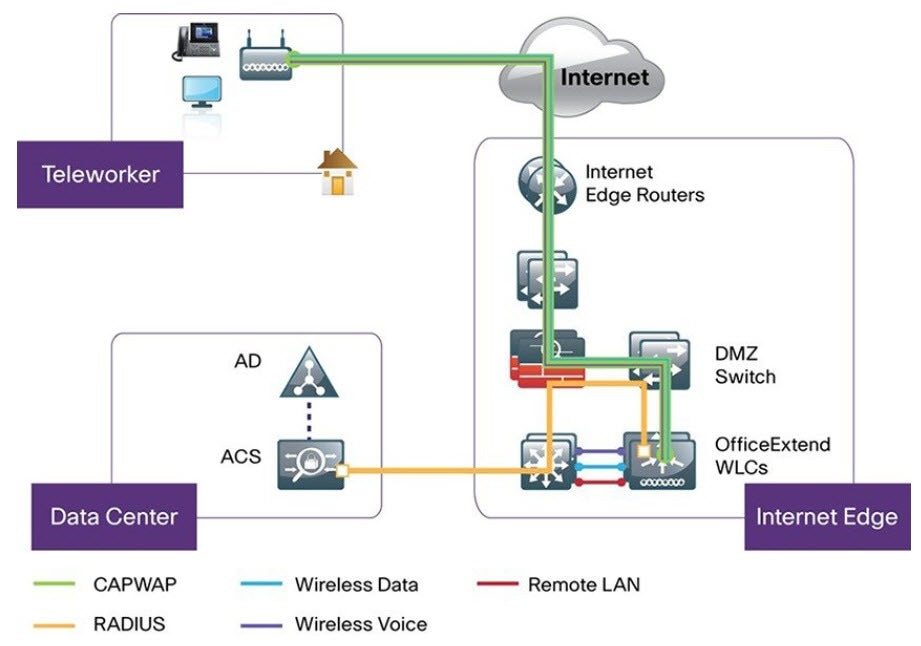
A remote teleworker site is a dedicated site that is used only to manage wireless controllers and remote teleworker access points (APs). To create a remote teleworker site, you need to enable the remote teleworker function on the site. When enabled, the remote teleworker function can’t be independently disabled for a site, building, or floor within the site's hierarchy. The site can only manage remote teleworker functions.

In a teleworker site, switching is performed centrally from the controller. You can’t configure the network profile for FlexConnect with local switching.

Before you begin

Procedure


Step 1

Create a site to manage remote teleworker APs. See Create, edit, and delete a site.

Step 2

Add buildings and floors. See Add, edit, and delete a building.

Step 3

Configure the wireless network settings for the remote teleworker site.

  1. From the main menu, choose Design > Network Settings > Wireless.

  2. From the left hierarchy tree, select the remote teleworker site.

  3. Click Remote Teleworker.

  4. Check the Enable Remote Teleworker check box.

  5. Click Save.

Step 4

Assign the controller to the site. See Assign an unprovisioned device to a site.

Step 5

Assign the APs to the site. See Assign an unprovisioned device to a site.

You can use serial numbers or MAC addresses but not a mixture of both, or you can upload a CSV file.

Step 6

In the wireless network settings, add the APs to the authorized APs list.

  1. From the left hierarchy tree, select Global.

  2. From the main menu, choose Design > Network Settings > Wireless.

  3. Click Security Settings.

  4. Click the AP Authorization List tab and add the APs that are allowed to join the controller. For more information, see Create an AP authorization list.

    The controller responds only to CAPWAP requests from APs that are in its authorization list.

Step 7

Provision the controller.

  1. From the main menu, choose Provision > Inventory.

    The Inventory window displays with the discovered devices listed.

  2. Locate the controller that you want to provision.

  3. Check the check box next to the device name.

  4. From the Actions drop-down list, choose Provision > Provision Device.

  5. In the Assign Site window, verify the assigned site, and click Save.

  6. Click Next.

  7. (Optional) On the Configuration window, under NAT Address for Remote Teleworker, click the Enable NAT Address check box and enter the NAT IP address.

  8. Click Next.

  9. In the Feature Templates window, click Next.

  10. In the Advanced Configuration window, click Next.

  11. In the Summary window, review the configuration settings, and click Deploy.

  12. In the Provision Device slide-in pane, choose Now, and click Apply.

Note

 
After deploying the configuration on the devices, the Task Progress bar displays the progress of the ongoing provisioning task under Activities > Tasks (which you can view by clicking the task name).

Step 8

After the Cisco Wireless Controller is provisioned, you can provision the APs.

  1. From the main menu, choose Provision > Inventory.

    The Inventory window displays with the discovered devices listed.

  2. Locate the APs that you want to provision.

  3. Check the check box next to the device names.

  4. From the Actions drop-down list, choose Provision > Provision Device.

  5. In the Assign Site window, click Choose a floor, and assign the APs to a floor.

  6. Click Save.

  7. Click Next.

  8. In the Configuration window, click Next.

  9. In the Summary window, review the configuration settings, and click Deploy.

  10. In the Provision Device slide-in pane, choose Now, and click Apply.


2 Supported with Cisco Aironet 1815 Teleworker Access Point only.