Chapter 3 - Installing the Cisco uBR924 Router
Available Languages
Table Of Contents
Installing the Cisco uBR924 Router
Cisco uBR924 Router Installation Checklist
Connecting to the Cable System
Connecting the Ethernet Cables
Connecting to Telephones or Fax Devices
Connecting the Backup POTS Connection
Router Power-On and Initialization Sequence
Installing the Cisco uBR924 Router
This chapter contains the following sections that provide instructions on installing the router, initial power-on, and verifying the installation:
•
Cisco uBR924 Router Installation Checklist
•
•
•
•
•
•

Caution
Cisco uBR924 Router Installation Checklist
Table 3-1 presents a checklist, identifying the installation tasks to complete at each subscriber site. Use this table as a guide while installing the router.
Table 3-1 Installation Checklist
Ensure the selected location to install the router is free of dust and meets all requirements.
Install the Cisco uBR924 router:
•
•
•
•
Check the power at the subscriber site before and after installation to ensure that you are receiving clean power. Ensure proper grounding.
Verify that each PC to be connected to the router has an Ethernet NIC and that TCP/IP networking with DHCP support is enabled. Ensure that all other PC prerequisites are met.
Connect the router's F-connector to the cable TV coaxial drop cable. (If the subscriber also subscribes to cable TV services, install a cable splitter/directional coupler and high-pass filter as appropriate.)
Connect the Cisco uBR924 router to CPE devices at the site:
•
•
Note
Connect the router's Phone V1+V2 and V2 connectors (RJ-11 to RJ-11) to telephones or fax devices directly, or to adapter(s) that allow multiple telephones or fax devices to be connected to the two VoIP telephone line(s). At subscriber sites supporting multiple voice devices on a single VoIP telephone line, ensure you have all certified connector assemblies/adapters and wiring items needed to support the configuration.
Note
Attach the 7-pin end of the power supply cord into the router's Power connector and connect the other end to the power supply. Plug the router's power supply into the wall outlet. Watch the router power on and initialize.
If applicable, connect the router's Line (RJ-11 to RJ-11) connector to a standard, analog POTS telephone line. Verify the telephone circuit/connection is working.
Power on all other devices at the subscriber site: PCs, Ethernet hub and all other equipment as applicable.
Ensure the data channel frequency has a sufficient RF signal level to meet your cable plant specifications and verify the RF input levels relative to a nearby analog video level:
•
•
Test the installation:
•
•
•
•
Physical Placement
Place the cable access router on a stable, flat surface such as a desktop, close to the cable TV drop connection and all devices to be connected at the subscriber site. The bottom, sides, and rear of the router must remain unobstructed to ensure adequate airflow and to prevent the unit from overheating. The rubber feet on the bottom of the router provide enough clearance when the unit is placed on a flat, hard surface. Cisco recommends at least 3 inches of clearance at the rear of the router.
Caution
Install the router in compliance with all national and local electrical codes such as:
•
•
•
Verifying Power Requirements
The cable access router uses one external AC-input power supply. The OK (power) LED on the front of the unit indicates that the power supply is supplying power to the unit when it is connected and operational.
The AC-input power supply uses a power factor corrector that allows the Cisco uBR924 cable access router to operate in any country where the input voltage is between 100 and 240 VAC, and 50 or 60 Hz. Different power cords are available to suit the country of operation.
Refer to Table A-1 for AC-input power supply specifications, including input voltage and operating frequency ranges. Cisco recommends that you follow these precautions:
•

Warning
•
•
Warning
•
•

Note
Caution
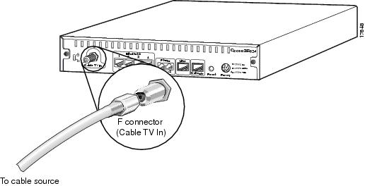
Connecting to the Cable System
To connect the Cisco uBR924 router to the cable system:
Step 1
Step 2
Step 3
Step 4
Figure 3-1 Connecting the CATV Coaxial Cable to the Cisco uBR924 Router
Caution
Step 5
Note
Caution
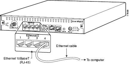
Connecting the Ethernet Cables
To connect the Cisco uBR924 router to computers and other CPE devices at the site:
Step 1
•
•
Step 2
Figure 3-2 Connecting the Ethernet Cable to the Cisco uBR924 Cable Access Router
Note
Step 3
Step 4
Warning
Hazardous network voltages are presented in WAN ports regardless of whether power to the unit is OFF or ON. To avoid electric shock, use caution when working near WAN ports. When detaching cables, detach the end away from the unit first.
Connecting to Telephones or Fax Devices
If you have purchased voice services from your service provider and are using a Cisco IOS image with voice support, use the following procedure to connect the Cisco uBR924 router to telephone or fax devices at the site:
Step 1
Note
Step 2
Figure 3-3 Telephone Cable and RJ-11 Connector
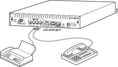
The V1+V2 connector supports either a single-line analog telephone or a two-line analog telephone that uses four wires. If using a two-line telephone, line 2 of the telephone behaves as if a single-line telephone is plugged into the second voice port. In this configuration, devices plugged into the V2 port act as extensions to the line 2 telephone.
Note
Step 3
Caution
Warning
Step 4
Warning
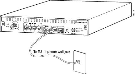
Connecting the Backup POTS Connection
To connect the Cisco uBR924 router to the backup, standard analog telephone line, follow the instructions below.
Warning
Step 1
Step 2
Figure 3-4 Backup Telephone Line Connector
Step 3
Warning
When the Cisco uBR924 router has a backup connection to the PSTN and the router loses power while VoIP calls are in progress, the subscriber can establish a voice connection by dialing out over the public switched telephone network (PSTN).
The backup POTS connection enables only one of the two VoIP lines connected to the Cisco uBR924 router to function during a power outage. Calls in progress prior to the power outage are disconnected. If power is re-established while a cutover call is in progress, that connection remains in place until the call is terminated. When the call is terminated, the router automatically reboots.
Note
Connecting Power
To connect AC-input power to the Cisco uBR924 router:
Step 1
Step 2
Figure 3-5 Connecting the Power Cord
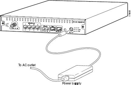
Step 3
Step 4
Warning
Step 5
Caution
Warning
Router Power-On and Initialization Sequence
When the Cisco uBR924 router is connected and powered on, it executes automatic self-diagnostic and installation procedures. The following procedure describes what you should see during this process.
Note
While the Cisco uBR924 cable access router initializes:
Step 1
Step 2
Note
Step 3
Step 4
•
•
•
•
Step 5
•
•
•
Step 6
Step 7
Step 8
Verifying Installation
Use the following procedures to verify the router's installation and operation; see Chapter 4, "Troubleshooting," if any problems occur.
Internet Connection
Use the following procedure to verify Internet connectivity between the PCs connected to the router's Ethernet ports and the internet access provided by the CMTS:
Step 1
Step 2
Step 3
Step 4
Step 5
Step 6
Note
If you install a cable access router at a time of year when the temperature is warmer, this step might assist you in determining how the cable access router will function over time. If the router does not function properly with the addition of attenuation, you should replace and reconfigure the coaxial cables at the subscriber site.
Step 7
Step 8
Step 9
Step 10
VoIP Telephone Connection
If the router has loaded a Cisco IOS image with voice support, use the following procedure to test the VoIP network by making a telephone call over the HFC and IP backbone network:
Step 1
If you do not hear a dial tone, the router's voice ports may be not enabled. Refer to the "VoIP Subsystem" section on page 4-11.
Step 2
The V1 or V2 front-panel LED (depending on the port the telephone is using) lights to denote a call is in progress and remains on until the call is disconnected.
Any call-progress indications and other signals that can be carried in-band (for example, remote phone ringing) are cut through the voice path as soon as an end-to-end audio channel is up. You either hear the far end telephone ringing until the caller picks up or you hear a busy signal if the far end telephone is already in use.
Step 3
VoIP Fax Connection
If the router has loaded a Cisco IOS image with voice support, use the following procedure to test the VoIP network by sending a fax over the HFC and IP backbone network:
Step 1
Step 2
The V1 or V2 LED (depending on the port the fax machine is using) lights to denote a fax is in progress and remains on until the fax call is disconnected.
Any call-progress indications and other signals that can be carried in-band (for example, remote phone ringing) are cut through the voice path as soon as an end-to-end audio channel is up. You either hear the far end ringing (depending on the fax machine setup) until the remote fax answers or you hear a busy signal if the remote fax is already in use.
Step 3
Step 4
Backup POTS Connection
To verify the backup POTS line to the PSTN is operational:
Step 1
Step 2
Step 3
Step 4
Step 5
Step 6
 Feedback
Contact Cisco
- Open a Support Case

- (Requires a Cisco Service Contract)
This Document Applies to These Products
- Collaboration Endpoints - Retired Products
- Conferencing - Retired Products
- Contact Center - Retired Products
- Optical Networking - Retired Products
- Routers - Retired Products
- Security - Retired Products
- Servers - Unified Computing (UCS) Retired Products
- Storage Networking Retired Products
- Switches - Retired Products
- Video - Retired Products
- Wireless - Retired Products