-
Cisco MDS 9000 Family Fabric Manager Configuration Guide, Release 3.4(1a)
-
Index
-
New and Changed Information
-
Preface
- Getting Started
- Installation and Switch Management
- Switch Configuration
-
Fabric Configuration
-
Configuring and Managing VSANs
-
SAN Device Virtualization
-
Creating Dynamic VSANs
-
Configuring Inter-VSAN Routing
-
Configuring and Managing Zones
-
Distributing Device Alias Services
-
Configuring Fibre Channel Routing Services and Protocols
-
Dense Wavelength Division Multiplexing
-
Managing FLOGI, Name Server, FDMI, and RSCN Databases
-
Discovering SCSI Targets
-
Configuring FICON
-
Advanced Features and Concepts
-
-
Security
-
Configuring FIPS
-
Configuring Users and Common Roles
-
Configuring SNMP
-
Configuring RADIUS and TACACS+
-
Configuring IPv4 Access Control Lists
-
Configuring Certificate Authorities and Digital Certificates
-
Configuring IPsec Network Security
-
Configuring FC-SP and DHCHAP
-
Configuring Port Security
-
Configuring Fabric Binding
-
- IP Services
- Intelligent Storage Services
- Network and Switch Monitoring
- Traffic Management
- Troubleshooting
-
Launching Fabric Manager in Cisco SAN-OS Releases Prior to 3.2(1)
-
Cisco Fabric Manager Unsupported Feature List
-
Interface Nonoperational Reason Codes
-
Managing Cisco FabricWare
-
Configuration Limits for Cisco MDS SAN-OS Release 3.1(x) and 3.2(x)
-
 Feedback
Table Of Contents
Configuring N Port Virtualization
NPV Guidelines and Requirements
NPV Traffic Management Guidelines
Configuring NPV Traffic Management
Configuring List of External Interfaces per Server Interface
Enable or Disable the Global Policy for Disruptive Load Balancing
Configuring N Port Virtualization
N Port virtualization (NPV) reduces the number of Fibre Channel domain IDs in SANs. Switches operating in the NPV mode do not join a fabric; rather, they pass traffic between NPV core switch links and end devices, which eliminates the domain IDs for these edge switches.
NPV is supported by the following Cisco MDS 9000 switches only:
•
Cisco MDS 9124 Multilayer Fabric Switch
•
•
•
Note
This chapter includes the following sections:
•
About NPV
Typically, Fibre Channel networks are deployed using a core-edge model with a large number of fabric switches connected to core devices. However, as the number of ports in the fabric increases, the number of switches deployed also increases, and you can end up with a dramatic increase in the number of domain IDs (the maximum number supported is 239). This challenge becomes even more difficult when additional blade chassis are deployed in Fibre Channel networks.
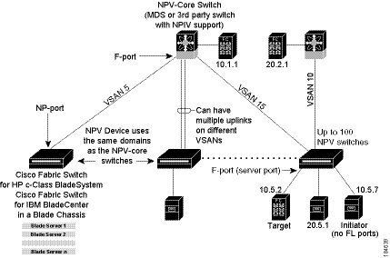
NPV addresses the increase in the number of domain IDs needed to deploy a large number of the ports by making a fabric or module switch appear as a host to the core Fibre Channel switch, and as a Fibre Channel switch to the servers in the fabric or blade switch. NPV aggregates multiple locally connected N ports into one or more external NP links, which shares the domain ID of the NPV core switch among multiple NPV switches (see Figure 21-1). NPV also allows multiple devices to attach to the same port on the NPV core switch, thereby reducing the need for more ports on the core.
Figure 21-1 Cisco NPV Fabric Configuration
While NPV is similar to N port identifier virtualization (NPIV), it does not offer exactly the same functionality. NPIV provides a means to assign multiple FC IDs to a single N port, and allows multiple applications on the N port to use different identifiers. NPIV also allows access control, zoning, and port security to be implemented at the application level. NPV makes use of NPIV to get multiple FCIDs allocated from the core switch on the NP port.
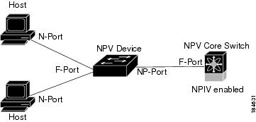
Figure 21-2 shows a more granular view of an NPV configuration at the interface level.
Figure 21-2 Cisco NPV Configuration-Interface View
NPV Mode
A switch is in NPV mode after a user has enabled NPV and the switch has successfully rebooted. NPV mode applies to an entire switch. All end devices connected to a switch that is in NPV mode must log in as an N port to use this feature (loop-attached devices are not supported). All links from the edge switches (in NPV mode) to the NPV core switches are established as NP ports (not E ports), which are used for typical interswitch links. NPIV is used by the switches in NPV mode to log in to multiple end devices that share a link to the NPV core switch.
Note
NP Ports
An NP port (proxy N port) is a port on a device that is in NPV mode and connected to the NPV core switch using an F port. NP ports behave like N ports except that in addition to providing N port behavior, they also function as proxies for multiple, physical N ports.
NP Links
An NP link is basically an NPIV uplink to a specific end device. NP links are established when the uplink to the NPV core switch comes up; the links are terminated when the uplink goes down. Once the uplink is established, the NPV switch performs an internal FLOGI to the NPV core switch, and then (if the FLOGI is successful) registers itself with the NPV core switch's name server. Subsequent FLOGIs from end devices in this NP link are converted to FDISCs. For more details refer to the "Internal FLOGI Parameters" section.
Server links are uniformly distributed across the NP links. All the end devices behind a server link will be mapped to only one NP link.
Internal FLOGI Parameters
When an NP port comes up, the NPV device first logs itself in to the NPV core switch and sends a FLOGI request that includes the following parameters:
•
•
After completing its FLOGI request, the NPV device registers itself with the fabric name server using the following additional parameters:
•
•
Note
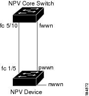
Figure 21-3 shows the internal FLOGI flows between an NPV core switch and an NPV device.
Figure 21-3 Internal FLOGI Flows
Table 21-1 identifies the internal FLOGI parameters that appear in Figure 21-3.
Although fWWN-based zoning is supported for NPV devices, it is not recommended because:
•
•
•
Default Port Numbers
Port numbers on NPV-enabled switches will vary depending on the switch model. For details about port numbers for NPV-eligible switches, see Chapter 11, "On-Demand Port Activation Licensing."
NPV CFS Distribution over IP
NPV devices use only IP as the transport medium. CFS uses multicast forwarding for CFS distribution. NPV devies do not have ISL connectivity and FC domain. To use CFS over IP, multicast forwarding has to be enabled on the ethernet IP switches all along the network that physically connects the NPV switch. You can also manually configure the static IP peers for CFS distribution over IP on NPV-enabled switches. For more information, see the Cisco MDS 9000 Family CLI Configuration Guide.
NPV Traffic Management
This sections discusses the following aspects of load balancing:
•
Auto
Before Cisco MDS SAN-OS release 3.3(1a), NPV supported automatic selection of external links. When a server interface is brought up, an external interface with the minimum load is selected from the available links. There is no manual selection on the server interfaces using the external links. Also, when a new external interface was brought up, the existing load was not distributed automatically to the newly available external interface. This newly brought up interface is used only by the server interfaces that come up after this interface.
Traffic Map
As in Cisco MDS SAN-OS release 3.3(1a) and later, NPV supports traffic management by allowing you to select and configure the external interfaces that the server uses to connect to the core switches.
Note
The NPV traffic management feature provides the following benefits:
•
•
•
•
Disruptive
Disruptive load balance works intependent of automatic selection of interfaces and configured traffic map of external interfaces. This feature forces re-init of the server interfaces to achieve load balance when this feature is enabled and whenever a new external interface comes up. To avoid flapping the server interfaces too often undesirably, enable this feature once and then disable it whenever the needed load balance is achieved.
If disruptive load balance is not enabled, you need to manually flap the server interface to move some of the load to a new external interface.
Multiple VSAN Support
By grouping devices into different NPV sessions based on VSANs, it is possible to support multiple VSANs on the NPV-enabled switch. The correct uplink must be selected based on the VSAN that the uplink is carrying.
NPV Guidelines and Requirements
Following are recommended guidelines and requirements when deploying NPV:
•
•
•
•
•
•
•
•
•
•
•
•
•
Note
NPV Traffic Management Guidelines
When deploying NPV traffic management, follow theseguidelines:
•
•
•
•
•
•
Configuring NPV
When you enable NPV, the system configuration is erased and the system is reboots, with the NPV mode enabled.
Note
switch#copy running bootflash:filename
The configuration can be reapplied later using the following command:switch#copy bootflash:filename running-config
SUMMARY STEPS
1.
2.
3.
4.
Note
•
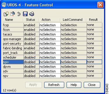
To use Fabric Manager and Device Manager to configure NPV, follow these steps:
Step 1
Figure 21-4 Enabling NPIV and NPV
Step 2
Step 3
Step 4
Step 5
Step 6
Step 7
Step 8
Step 9
Step 10
Configuring NPV Traffic Management
The NPV traffic management feature is enabled after configuring NPV. Configuring NPV traffic management involves configuring a list of external interfaces to the servers, and enabling or disabling disruptive load balancing.
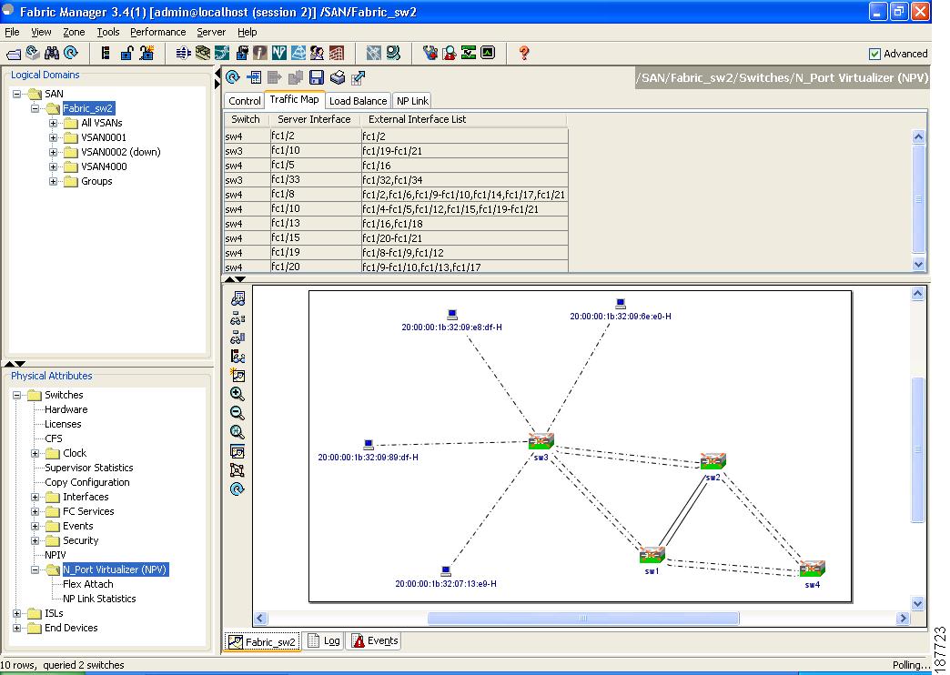
Configuring List of External Interfaces per Server Interface
A list of external interfaces are linked to the server interfaces when the server interface is down, or if the specified external interface list includes the external interface already in use.
To configure the list of external interfaces per server interface using Fabric Manager, perform the following tasks:
Step 1
Figure 21-5 NPV Traffic Map Tab
Step 2
Step 3
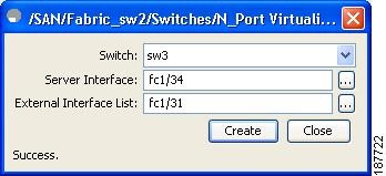
icon in the toolbar or right click and then select Create Row....
Step 4
Figure 21-6 Map Entry Dialog Box
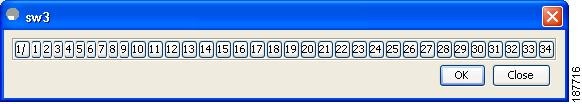
Step 5
Figure 21-7 Port Selection Dialog Box
Note
To delete the map entry, select the row from the Traffic Map tab, and then click the
icon in the toolbar or right click and select Delete Row.
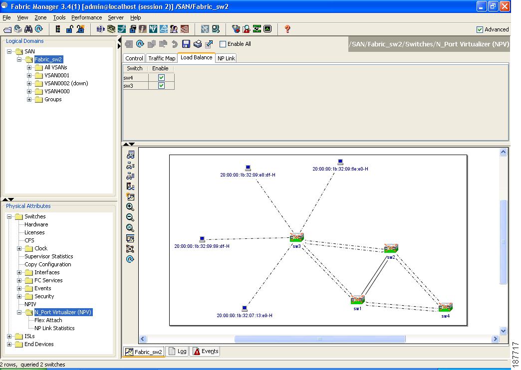
Enable or Disable the Global Policy for Disruptive Load Balancing
Disruptive load balancing allows you to review the load on all the external interfaces and balance the load disruptively. Disruptive load balancing is done by moving the servers using heavily loaded external interfaces, to the external interfaces running with fewer loads.
To enable disruptive load balancing using Fabric Manager, perform the following tasks:
Step 1
Step 2
Step 3
To enable disruptive load balancing on all the switches, check the Enable All checkbox as shown in Figure 21-8.
Figure 21-8 NPV Load Balance Tab
Using the NPV Setup Wizard
To configure NPV using the wizard, follow these steps:
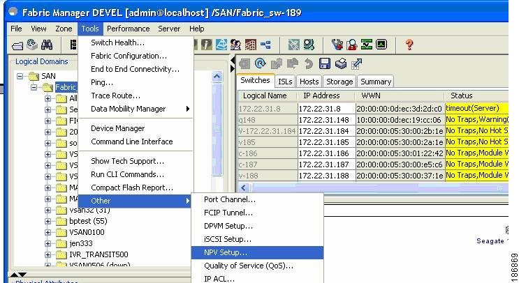
Step 1
(See Figure 21-9.)Figure 21-9 Launching NPV Setup Wizard
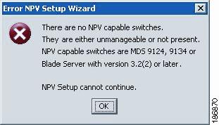
Before the wizard starts, Fabric Manager checks if there are any NPV and NPIV capable switches from the client's SAN. An NPV-capable switch has to be a Cisco MDS 9124, 9134, a HP Blade Server, or an IBM Blade Server with SAN-OS version 3.2.2 and later. An NPIV capable switch has to be Cisco switch with SAN-OS 3.0.1 and later. If there are no NPV-capable switches, FM displays an error message.
(See Figure 21-10.)Figure 21-10 Error in Launching
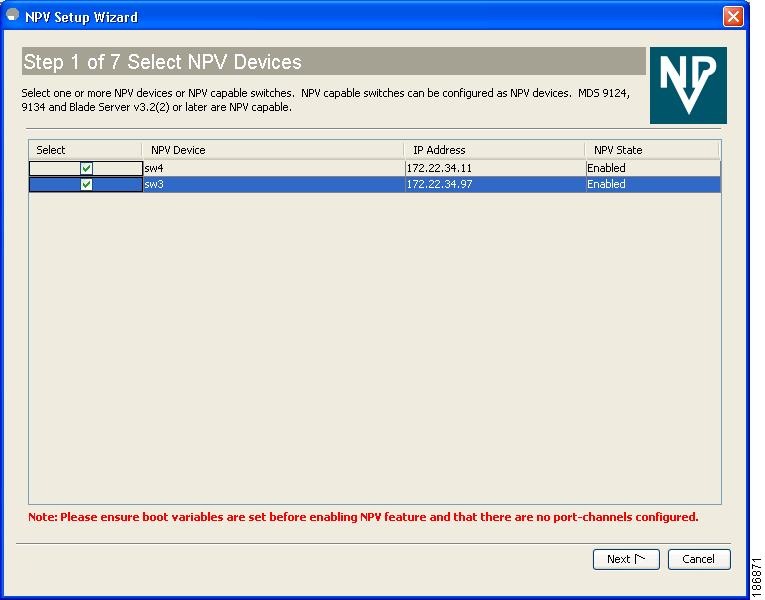
Step 2
Figure 21-11 Selecting the NPV Devices
A table lists all the available NPV-capable switches including the switches on which NPV is not yet enabled. Check the check boxes to select the required NPV devices. On devices that are not NPV enabled, this wizard will enable NPV on the devices in the final step.
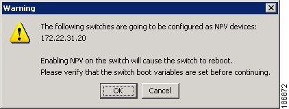
If you choose switches that are NPV disabled and click Next, a warning message appears with a list of IP addresses of the NPV devices on which NPV will be enabled. Enabling NPV on the switch will result in reboot of the switch. Boot variables of the switches have to be set, to enable NPV on them through this wizard. (See Figure 21-12.)
Figure 21-12 Warning to Enable NPV Feature on NPV-Capable Switches
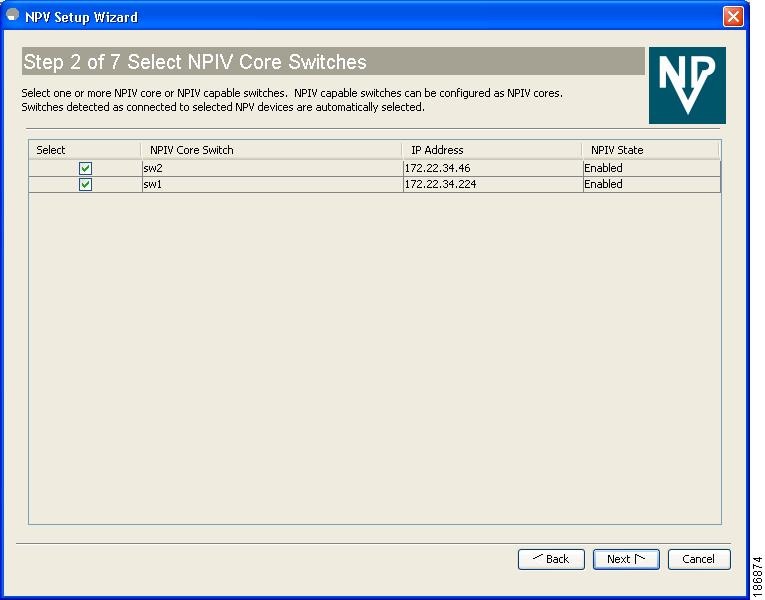
Step 3
Figure 21-13 Selecting the NPIV Core Switches
Check the check boxes to select the required NPIV core switches. The table lists all the available NPIV core switches including the core switches that have not yet enabled the NPIV feature. The NPIV core switches which are not NPIV enabled, this wizard will enable NPIV on them in the final step.
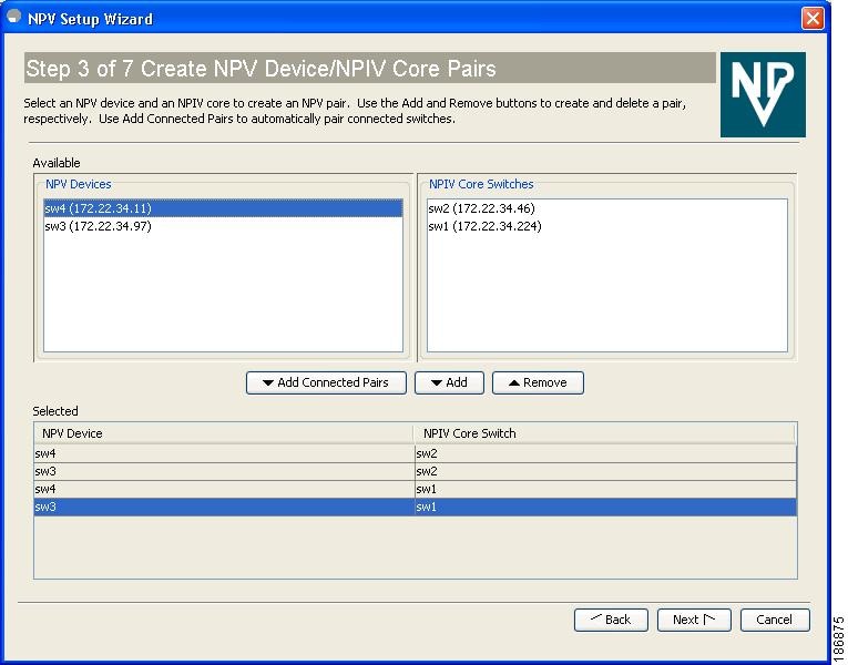
Step 4
Figure 21-14 Creating NPV Device and NPIV Core Switch Pairs
Based on selections in the previous steps, the wizard displays all available NPV devices and NPIV core switches in separate lists. You can select one from each list and click Add or Remove buttons to create new NPV device and NPIV core switch combinations or pairs.
The NPV wizard checks if there are any NPIV core switches that are already connected to the NPV devices selected in the previous step. Click the Add Connected Pairs button to add a list of all the existing pairs that are interconnected, to the Selected table.
The Selected table below is then populated with both the existing and the intended pairs. Each NPIV core switch can be paired with multiple NPV devices.
After Step 6 the wizard prompts you to physically connect the new pairs that are not yet connected.
On the switches that are not paired, the NPV wizard enables the NPV and NPIV modes. However, there is a possibility that these unpaired switches may be segmented and lose their presence on the fabric.
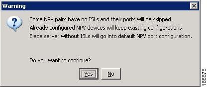
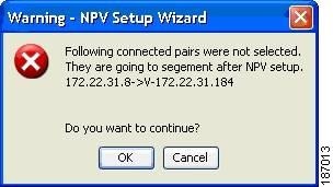
After you click the Next button in Step 3 of 6, the wizard determines if you have selected all the connected pairs. A warning message is displayed (See Figure 21-17), that lists all the connected pairs that you have not selected and warns that they will be segmented after the NPV setup.
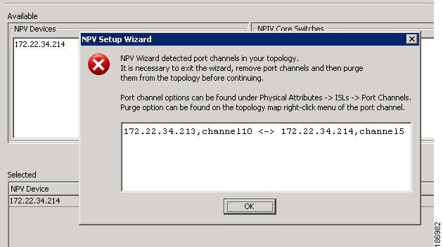
Note
•
Figure 21-15 Port Channel Group
Detected.
Figure 21-16 Warning, NPV Setup Wiza
rd
Figure 21-17 Warning, NPV Setup Wizard.
Step 5
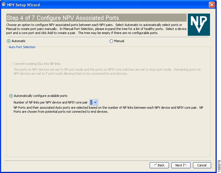
(See Figure 21-18.)Figure 21-18 Configuring NPV Associated Ports by the Automatic Metho
d
The Auto Port Selection has two options.
Choosing the first option allows you to convert the existing ISLs to be run as NPV links. If you want ISLs to take priority, then choose the Convert existing ISLs option.
The wizard discovers ISLs (Up or Down) between the selected switches, that are available at the time of wizard launch.
Choosing the second option allows the NPV wizard to automatically configure Free ports for NPV usage. In the second option, you can choose up to a maximum of Six additional NPV links per NPV device and core switch pair.
During automatic port selection on the NPV switch, ports are defined as licensed FC ports with "Operational status" = Auto and "Status Cause" = none(2), offline(8), or sfp not present(29) and "Operational Status" = TE or E.
Ports on the NPV switch are selected in the following way:
The ISLs are considered in the second method. The selection algorithm spreads out the free port selections, so that the first port in every four ports is selected, for example, the 1st, 5th, 9th, etc. If after going through the 1st port in every four you still have not selected enough ports (because the preferred ports were not free) then move to the second port in every four, for example, the 2nd, 6th, 10th etc. Different switches have different port preferences.
Ports on the NPIV switch are selected in the following way:
During automatic port selection on the NPIV switch free ports are defined as ports that are licensed FC ports and ports that have "Operational status" = Auto and "Status Cause" =none(2), offline(8) or sfp not present(29). If the ports are found in any other operational state, (for example F, NP, E, TE etc), then they are considered used, except for E and TE ports that are in ISLs connected to NPV device switches that will be enabled for NPV mode in this wizard session, as they will be considered to be free. However, these ISL ports will not necessarily be the ports selected by the automatic port selection algorithm as they are treated no different then any other free port. If you want to convert those used ISL ports, then choose the convert existing ISLs first and then run the wizard a second time choosing Automatic port selection (option 2) to add additional links.
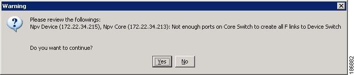
When you choose to configure ports from available ports, the wizard searches for ports that are not currently participating in NP link configuration. It is possible that all ports can be participating in NP port configuration. In that case a warning message is displayed. (See Figure 21-19.)
Note
Figure 21-19 Warning, not Enough Number of Ports.
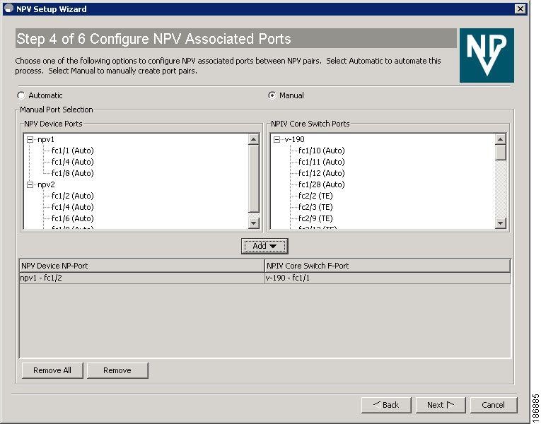
Figure 21-20 Configuring NPV Associated Ports by the Manual Method.
Select the Manual method to manually create port pairs (see Figure 21-20.) Click on a satellite switch and select the NP device port expanded under each of the NPV switches listed. Then select the required the F port on the NPIV core switch and click Add for them to pair.
During manual selection from the list for NPV and NPIV, ports are defined as the licensed FC ports with "Operational status" = Auto and "Status Cause" = none(2), offline(8), or sfp not present(29) and 'Operational Status" = TE or E.
Based on user selection, the wizard decides which ports are set to NP ports on the NPV device side and which are F ports on the core switch side to make an NPV connection.
Note
Figure 21-21 Message Alert to Connect Port Pair.
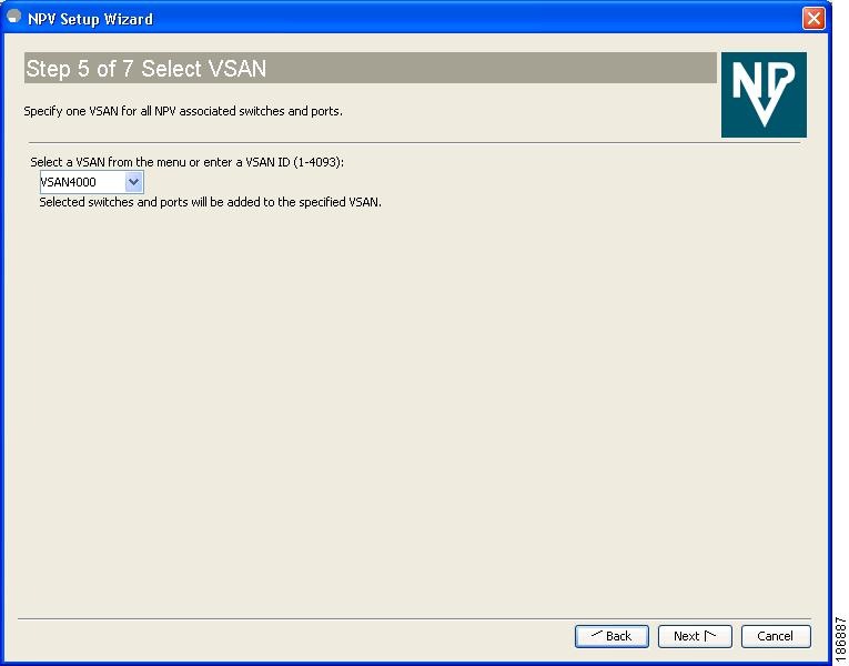
Step 6
Figure 21-22 Selecting a VSAN
From the drop-down list select a VSAN or enter a VSAN ID to specify the VSAN. All selected NPV devices and NPIV core switches are added to the specified VSAN. All ports on the selected NPV devices and associated ports on the NPIV core switches are added to the VSAN.
The VSAN configuration is applied in the final step.
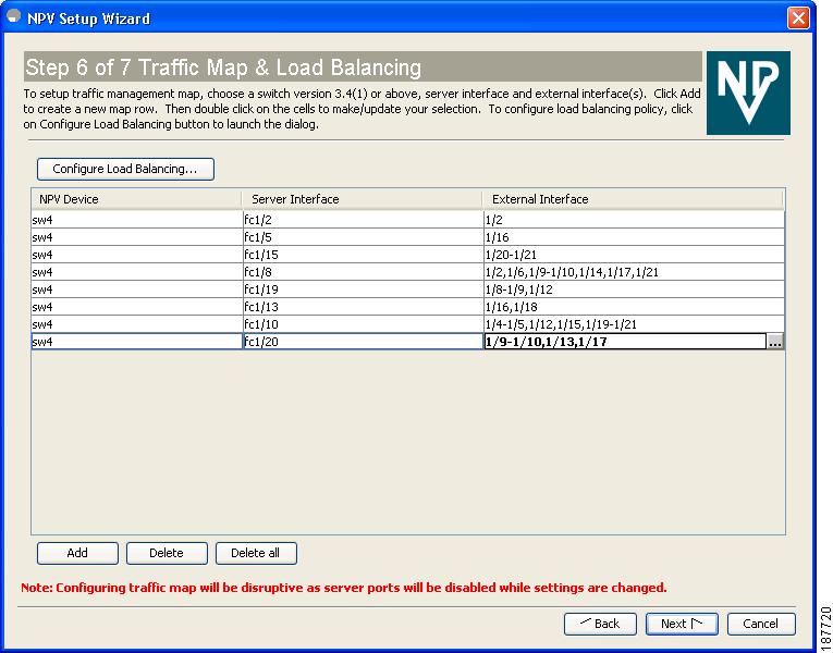
Step 7
Figure 21-23 Mapping Server Interfaces with External Interfaces for Load Balancing
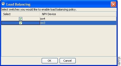
To select the NPV devices that need load balancing, click Configure Load Balancing, and then select the NPV devices for disruptive load balancing as shown in Figure 21-24.
Figure 21-24 Select the NPV Devices for Load Balancing
To set up the traffic management map, select at least one switch of version 3.4(1) or above, a server interface, and external interfaces. To add a map entry, follow these steps:
a.
b.
c.
Figure 21-25 Select the Interfaces
Note
d.
To delete an exsiting map entry, select the row, and then click Delete.
To delete all the existing map entries, click Delete All.
Step 8
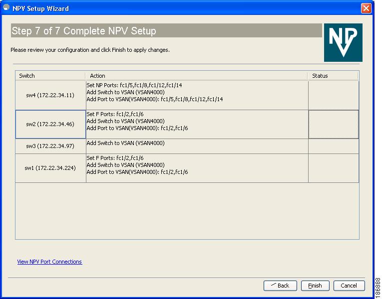
Figure 21-26 Completing the NPV Setup
Enable Switch Feature lists the switches, the impending actions against them with reference to features, and the resultant status.
Set Port Type lists the switches and the ports to be set on the switches to configure NPV associate ports.
Configure VSAN lists the switches and ports to be added to the specified VSAN.
Click >> to view the expanded the panes. Click << to collapse the panes.
A progress bar at the bottom of the window indicates the overall extent of completion of the configuration tasks. A text message that runs below the progress bar indicates the current task in progress.
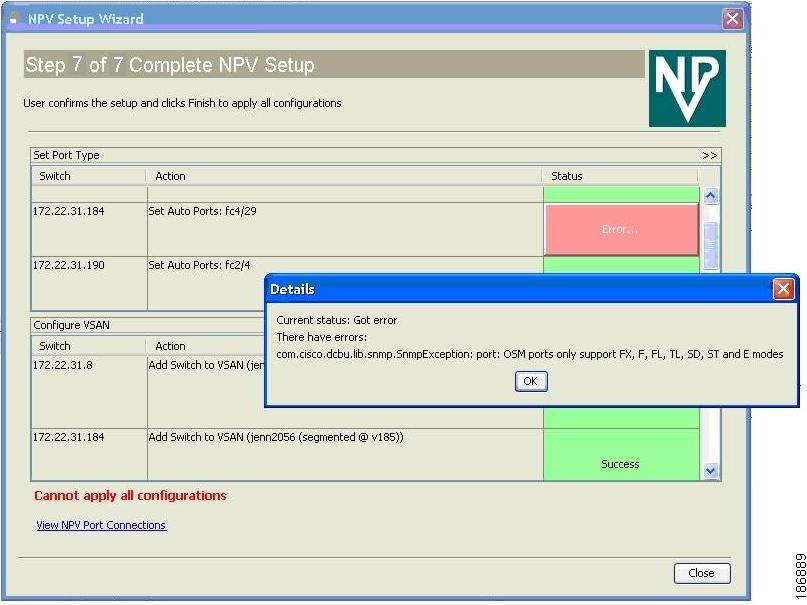
The status cells against each item indicate In progress, Success, and Error states. When a configuration cannot be applied, the status cell against the task is changed to Error. Click Error to view Details. A message is displayed in place of the progress bar stating, `Cannot apply all configurations,' as shown in Figure 21-27
Figure 21-27 Error in Applying Configurations and Details
After the completion of all the tasks a link View NPV Port Connections is displayed in the place of the progress bar. (See Figure 21-27.)
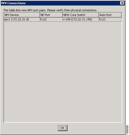
Click View NPV Port Connections to view the NPV port connections in a table (See Figure 21-29). Refer to this list to verify the physical connections between NP Port on NPV devices and Auto ports) on NPIV core switches. The physical connections already exist in case of the ISLs and they have to be verified. In some cases when the physical connections do not exist, they have to be established manually.
Figure 21-28 New NPV Port Pairs
Figure 21-29 New NPV Port Pairs, Details
DPVM Configuration
When NPV is enabled, the following requirements must be met before you configure DPVM on the NPV core switch:
•
•
For details about DPVM configuration, see Chapter 28, "Creating Dynamic VSANs."
NPV and Port Security
Port security is enabled on the NPV core switch on a per interface basis. To enable port security on the NPV core switch for devices logging in via NPV, you must adhere to the following requirements:
•
•
Once these requirements are met, you can enable port security as you would in any other context. For details about enabling port security, see Chapter 46, "Configuring Port Security."