-
Cisco MDS 9000 Family Fabric Manager Configuration Guide, Release 3.4(1a)
-
Index
-
New and Changed Information
-
Preface
- Getting Started
- Installation and Switch Management
- Switch Configuration
-
Fabric Configuration
-
Configuring and Managing VSANs
-
SAN Device Virtualization
-
Creating Dynamic VSANs
-
Configuring Inter-VSAN Routing
-
Configuring and Managing Zones
-
Distributing Device Alias Services
-
Configuring Fibre Channel Routing Services and Protocols
-
Dense Wavelength Division Multiplexing
-
Managing FLOGI, Name Server, FDMI, and RSCN Databases
-
Discovering SCSI Targets
-
Configuring FICON
-
Advanced Features and Concepts
-
-
Security
-
Configuring FIPS
-
Configuring Users and Common Roles
-
Configuring SNMP
-
Configuring RADIUS and TACACS+
-
Configuring IPv4 Access Control Lists
-
Configuring Certificate Authorities and Digital Certificates
-
Configuring IPsec Network Security
-
Configuring FC-SP and DHCHAP
-
Configuring Port Security
-
Configuring Fabric Binding
-
- IP Services
- Intelligent Storage Services
- Network and Switch Monitoring
- Traffic Management
- Troubleshooting
-
Launching Fabric Manager in Cisco SAN-OS Releases Prior to 3.2(1)
-
Cisco Fabric Manager Unsupported Feature List
-
Interface Nonoperational Reason Codes
-
Managing Cisco FabricWare
-
Configuration Limits for Cisco MDS SAN-OS Release 3.1(x) and 3.2(x)
-
 Feedback
Table Of Contents
Configuring Fabric Congestion Control and QoS
Enabling or Disabling Control Traffic
About Service Policy Definition
About Service Policy Enforcement
About the DWRR Traffic Scheduler Queue
Changing the Weight in a DWRR Queue
Configuring Fabric Congestion Control and QoS
Fibre Channel Congestion Control (FCC) is a Cisco proprietary flow control mechanism that alleviates congestion on Fibre Channel networks.
Quality of service (QoS) offers the following advantages:
•
Provides relative bandwidth guarantee to application traffic.
•
•
This chapter provides details on the QoS and FCC features provided in all switches. It includes the following sections:
•
•
FCC
FCC reduces the congestion in the fabric without interfering with the standard Fibre Channel protocols. This section contains the following topics:
About FCC
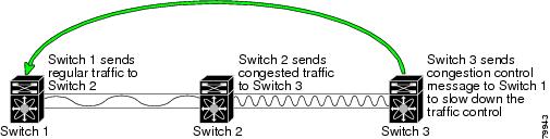
The FCC protocol increases the granularity and the scale of congestion control applied to any class of traffic (see Figure 57-1).
Figure 57-1 FCC Mechanisms
Edge quench congestion control provides feedback to the source about the rate at which frames should be injected into the network (frame intervals).
Note
FCC Process
When a node in the network detects congestion for an output port, it generates an edge quench message. These frames are identified by the Fibre Channel destination ID (DID) and the source ID. A switch from other vendors simply forwards these frames.
Any receiving switch in the Cisco MDS 9000 Family handles frames in one of these ways:
•
•
The behavior of the flow control mechanism differs based on the Fibre Channel DID:
•
•
•
All switches (including the edge switch) along the congested path process path quench frames. However, only the edge switch processes edge quench frames.
Enabling FCC
By default, the FCC protocol is disabled. FCC can only be enabled for the entire switch.
Tip
To enable or disable the FCC feature using Fabric Manager, follow these steps:
Step 1
The FCC information is displayed in the Information pane. The General tab is the default.
Step 2
Step 3
Step 4
Assigning FCC Priority
To assign FCC priority using Fabric Manager, follow these steps:
Step 1
The FCC information is displayed in the Information pane. The General tab is the default.
Step 2
Step 3
Step 4
QoS
QoS implementation in the Cisco MDS 9000 Family follows the differentiated services (DiffServ) model. The DiffServ standard is defined in RFCs 2474 and 2475.
All switches support the following types of traffic:
•
•
•
•
•
About Control Traffic
The Cisco MDS 9000 Family supports QoS for internally and externally generated control traffic. Within a switch, control traffic is sourced to the supervisor module and is treated as a high priority frame. A high priority status provides absolute priority over all other traffic and is assigned in the following cases:
•
•
Enabling or Disabling Control Traffic
By default, the QoS feature for certain critical control traffic is enabled. These critical control frames are assigned the highest (absolute) priority.
Tip
Toenable or disable the high priority assignment for control traffic using Fabric Manager, follow these steps:
Step 1
The QoS control traffic information is displayed in the Information pane. The Control tab is default.
Step 2
Step 3
Step 4
About Data Traffic
Online transaction processing (OLTP), which is a low volume, latency sensitive application, requires quick access to requested information. Backup processing application require high bandwidth but are not sensitive to latency. In a network that does not support service differentiation, all traffic is treated identically—they experience similar latency and are allocated similar bandwidths. The QoS feature in the Cisco MDS 9000 Family switches provides these guarantees.
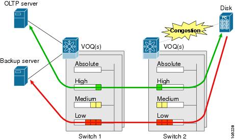
Data traffic can be prioritized in distinct levels of service differentiation: low, medium, or high priority. You can apply QoS to ensure that Fibre Channel data traffic for your latency-sensitive applications receive higher priority over throughput-intensive applications such as data warehousing (see Figure 57-2).
Figure 57-2 Prioritizing Data Traffic
In Figure 57-2, the OLTP traffic arriving at Switch 1 is marked with a high priority level of throughput classification (class map) and marking (policy map). Similarly, the backup traffic is marked with a low priority level. The traffic is sent to the corresponding priority queue within a virtual output queue (VOQ).
A deficit weighted round robin (DWRR) scheduler configured in the first switch ensures that high priority traffic is treated better than low priority traffic. For example, DWRR weights of 70:20:10 implies that the high priority queue is serviced at 7 times the rate of the low priority queue. This guarantees lower delays and higher bandwidths to high priority traffic if congestion sets in. A similar configuration in the second switch ensures the same traffic treatment in the other direction.
If the ISL is congested when the OLTP server sends a request, the request is queued in the high priority queue and is serviced almost immediately since the high priority queue is not congested. The scheduler assigns its priority over the backup traffic in the low priority queue.
Note
A similar occurrence in Switch 2 sends a response to the transaction request. The round trip delay experienced by the OLTP server is independent of the volume of low priority traffic or the ISL congestion. The backup traffic uses the available ISL bandwidth when it is not used by the OLTP traffic.
Tip
VSAN Versus Zone-Based QoS
While you can configure both zone-based QoS and VSAN-based QoS configurations in the same switch, both configurations have significant differences. Table 57-1 highlights the differences between configuring QoS priorities based on VSANs versus zones.
See the "About Zone-Based Traffic Priority" section on page 30-40 for details on configuring a zone-based QoS policy.
Configuring Data Traffic
To configure QoS using Fabric Manager, follow these steps:.
Step 1
Step 2
Step 3
Step 4
Tip
About Class Map Creation
Use the class map feature to create and define a traffic class with match criteria to identify traffic belonging to that class. The class map name is restricted to 63 alphanumeric characters and defaults to the match-all option. Flow-based traffic uses one of the following values:
•
•
Note
•
Tip
Creating a Class Map
To create a class map using Fabric Manager, follow these steps:
Step 1
The QoS information is displayed in the Information pane shown in Figure 57-3. The Control tab is the default.
Figure 57-3 Quality of Service Control Tab
Step 2
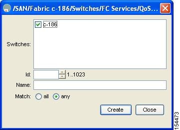
You see the Create Class Maps dialog box shown in Figure 57-4.
Figure 57-4 Create Class Maps Dialog Box
Step 3
Step 4
Step 5
Step 6
Step 7
About Service Policy Definition
Service policies are specified using policy maps. Policy maps provide an ordered mapping of class maps to service levels. You can specify multiple class maps within a policy map, and map a class map to a high, medium, or low service level. The default priority is low. The policy map name is restricted to 63 alphanumeric characters.
As an alternative, you can map a class map to a differentiated services code point (DSCP).The DSCP is an indicator of the service level for a specified frame. The DSCP value ranges from 0 to 63, and the default is 0. A DSCP value of 46 is disallowed.
The order of the class maps within a policy map is important to determine the order in which the frame is compared to class maps. The first matching class map has the corresponding priority marked in the frame.
Note
Note
About Service Policy Enforcement
When you have configured a QoS data traffic policy, you must enforce the data traffic configuration by applying that policy to the required VSAN(s). If you do not apply the policy to a VSAN, the data traffic configuration is not enforced. You can only apply one policy map to a VSAN.
Note
About the DWRR Traffic Scheduler Queue
The Cisco SAN-OS software supports four scheduling queues:
•
•
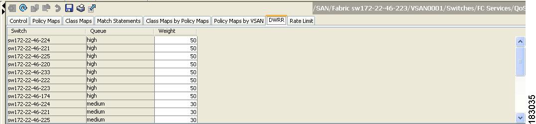
The DWRR scheduler services the queues in the ratio of the configured weights. Higher weights translate to proportionally higher bandwidth and lower latency. The default weights are 50 for the high queue, 30 for the medium queue, and 20 for the low queue. Decreasing order of queue weights is mandated to ensure the higher priority queues have a higher service level, though the ratio of the configured weights can vary (for example, one can configure 70:30:5 or 60:50:10 but not 50:70:10).
Table 57-2 describes the QoS behavior for Generation 1 and Generation 2 switching modules.
Changing the Weight in a DWRR Queue
To change the weight in a DWRR queue using Fabric Manager, follow these steps:
Step 1
The QoS control traffic information is displayed in the Information pane shown in Figure 57-5. The default is the Control tab.
Figure 57-5 Quality of Service Control Tab
Step 2
You see the queue status and weight (see Figure 57-6).
Figure 57-6 QoS Queue Status and Weight
Step 3
Step 4
Example Configuration
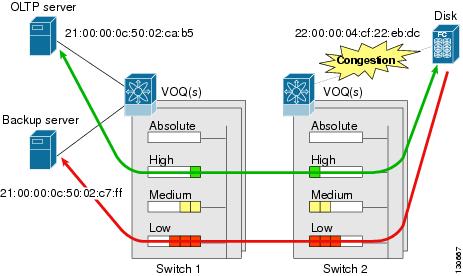
This section describes a configuration example for the application illustrated in Figure 57-7.
Figure 57-7 Example Application for Traffic Prioritization
Both the OLTP server and the backup server are accessing the disk. The backup server is writing large amounts of data to the disk. This data does not require specific service guarantees. The volumes of data generated by the OLTP server to the disk are comparatively much lower but this traffic requires faster response because transaction processing is a low latency application.
The point of congestion is the link between Switch 2 and the disk, for traffic from the switch to the disk. The return path is largely uncongested as there is little backup traffic on this path.
Service differentiation is needed at Switch 2 to prioritize the OLTP-server-to-disk traffic higher than the backup-server-to-disk traffic.
To configure traffic prioritization for the example application, follow these steps:
Step 1
Step 2
Step 3
Step 4
Step 5
Congestion could occur anywhere in the example configuration. To address congestion of the return path at both switches, you need to create two more class maps and include them in the policy map as follows:
Step 1
Step 2
Step 3
Ingress Port Rate Limiting
A port rate limiting feature helps control the bandwidth for individual Fibre Channel ports. Port rate limiting is also referred to as ingress rate limiting because it controls ingress traffic into a Fibre Channel port. The feature controls traffic flow by limiting the number of frames that are transmitted out of the exit point on the MAC. Port rate limiting works on all Fibre Channel ports. The rate limit ranges from 1 to 100% and the default is 100%.
Note
This feature can only be configured if the QoS feature is enabled and if this configuration is performed on a Cisco MDS 9100 series switch, Cisco MDS 9216i switch, or MPS-14/2 module.
To configure the port rate limiting value using Fabric Manager, follow these steps:
Step 1
The QoS control traffic information is displayed in the Information pane shown in Figure 57-8. The default is the Control tab.
Figure 57-8 Quality of Service Control Tab
Step 2
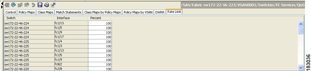
You see the information shown in Figure 57-9.
Figure 57-9 Rate Limits for Switch Interfaces
Step 3
Step 4
Step 5
Default Settings
Table 57-3 lists the default settings for FCC, QoS, and rate limiting features.
.
Table 57-3 Default FCC, QoS, and Rate Limiting Settings
FCC protocol
Disabled.
QoS control traffic
Enabled.
QoS data traffic
Disabled.
Zone-based QoS priority
Low.
Rate limit
100%