-
Cisco MDS 9000 Family Fabric Manager Configuration Guide, Release 3.4(1a)
-
Index
-
New and Changed Information
-
Preface
- Getting Started
- Installation and Switch Management
- Switch Configuration
-
Fabric Configuration
-
Configuring and Managing VSANs
-
SAN Device Virtualization
-
Creating Dynamic VSANs
-
Configuring Inter-VSAN Routing
-
Configuring and Managing Zones
-
Distributing Device Alias Services
-
Configuring Fibre Channel Routing Services and Protocols
-
Dense Wavelength Division Multiplexing
-
Managing FLOGI, Name Server, FDMI, and RSCN Databases
-
Discovering SCSI Targets
-
Configuring FICON
-
Advanced Features and Concepts
-
-
Security
-
Configuring FIPS
-
Configuring Users and Common Roles
-
Configuring SNMP
-
Configuring RADIUS and TACACS+
-
Configuring IPv4 Access Control Lists
-
Configuring Certificate Authorities and Digital Certificates
-
Configuring IPsec Network Security
-
Configuring FC-SP and DHCHAP
-
Configuring Port Security
-
Configuring Fabric Binding
-
- IP Services
- Intelligent Storage Services
- Network and Switch Monitoring
- Traffic Management
- Troubleshooting
-
Launching Fabric Manager in Cisco SAN-OS Releases Prior to 3.2(1)
-
Cisco Fabric Manager Unsupported Feature List
-
Interface Nonoperational Reason Codes
-
Managing Cisco FabricWare
-
Configuration Limits for Cisco MDS SAN-OS Release 3.1(x) and 3.2(x)
-
 Feedback
Table Of Contents
Configuring IPsec Network Security
Supported IPsec Transforms and Algorithms
Supported IKE Transforms and Algorithms
IPsec Digital Certificate Support
Implementing IPsec Without CAs and Digital Certificates
Implementing IPsec with CAs and Digital Certificates
How CA Certificates Are Used by IPsec Devices
Configuring IPsec Using FCIP Wizard
Manually Configuring IPsec and IKE
Optional IKE Parameter Configuration
Configuring the Keepalive Time for a Peer
Configuring the Initiator Version
Clearing IKE Tunnels or Domains
The any Keyword in Crypto IPv4-ACLs
SA Establishment Between Peers
Crypto Map Configuration Guidelines
Configuring the AutoPeer Option
Configuring Perfect Forward Secrecy
About Crypto Map Set Application
Configuring IPsec Network Security
IP security (IPsec) protocol is a framework of open standards that provides data confidentiality, data integrity, and data authentication between participating peers. It is developed by the Internet Engineering Task Force (IETF). IPsec provides security services at the IP layer, including protecting one or more data flows between a pair of hosts, between a pair of security gateways, or between a security gateway and a host. The overall IPsec implementation is the latest version of RFC 2401. Cisco SAN-OS IPsec implements RFC 2402 through RFC 2410.
IPsec uses the Internet Key Exchange (IKE) protocol to handle protocol and algorithm negotiation and to generate the encryption and authentication keys used by IPsec. While IKE can be used with other protocols, its initial implementation is with the IPsec protocol. IKE provides authentication of the IPsec peers, negotiates IPsec security associations, and establishes IPsec keys. IKE uses RFCs 2408, 2409, 2410, and 2412, and additionally implements the draft-ietf-ipsec-ikev2-16.txt draft.
Note
The term IPsec is sometimes used to describe the entire protocol of IPsec data services and IKE security protocols and is other times used to describe only the data services.
This chapter includes the following sections:
•
•
•
•
About IPsec
Note
IPsec provides security for transmission of sensitive information over unprotected networks such as the Internet. IPsec acts at the network layer, protecting and authenticating IP packets between participating IPsec devices (peers).
IPsec provides the following network security services. In general, the local security policy dictates the use of one or more of these services between two participating IPsec devices:
•
•
•
•
Note
With IPsec, data can be transmitted across a public network without fear of observation, modification, or spoofing. This enables applications such as Virtual Private Networks (VPNs), including intranets, extranets, and remote user access.
IPsec as implemented in Cisco SAN-OS software supports the Encapsulating Security Payload (ESP) protocol. This protocol encapsulates the data to be protected and provides data privacy services, optional data authentication, and optional anti-replay services.
Note
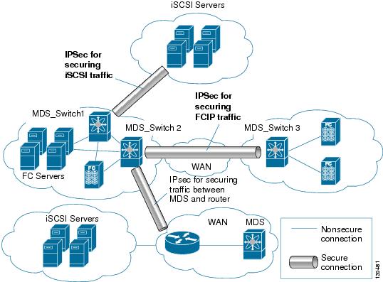
Figure 35-1 shows different IPsec scenarios.
Figure 35-1 FCIP and iSCSI Scenarios Using MPS-14/2 Modules
About IKE
IKE automatically negotiates IPsec security associations and generates keys for all switches using the IPsec feature. Specifically, IKE provides these benefits:
•
•
•
•
Note
IPsec Prerequisites
To use the IPsec feature, you need to perform the following tasks:
•
•
Note
Using IPsec
To use the IPsec feature, follow these steps:
Step 1
Step 2
Note
This section contains the following topics:
•
•
IPsec Compatibility
IPsec features are compatible with the following Cisco MDS 9000 Family hardware:
•
•
•
IPsec features are compatible with the following fabric setup:
•
•
•
–
–
–
–
–
–
–
Note
IPsec and IKE Terminology
The terms used in this chapter are explained in this section.
•
–
–
–
–
–
–
The Cisco SAN-OS implementation of IPsec does not support transport mode.
Note
•
•
–
–
•
•
•
•
–
–
Supported IPsec Transforms and Algorithms
The component technologies implemented for IPsec include the following transforms:
•
•
•
Note
•
•
•
Supported IKE Transforms and Algorithms
The component technologies implemented for IKE include the following transforms:
•
•
•
•
Note
•
•
•
IPsec Digital Certificate Support
This section describes the advantages of using certificate authorities (CAs) and digital certificates for authentication.
For more information on CAs and digital certificates, see Chapter 34, "Configuring Certificate Authorities and Digital Certificates."
Implementing IPsec Without CAs and Digital Certificates
Without a CA and digital certificates, enabling IPsec services (such as encryption) between two Cisco MDS switches requires that each switch has the key of the other switch (such as an RSA public key or a shared key). You must manually specify either the RSA public keys or preshared keys on each switch in the fabric using IPsec services. Also, each new device added to the fabric will require manual configuration of the other switches in the fabric to support secure communication.
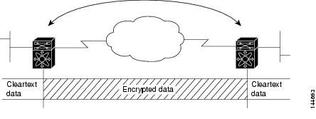
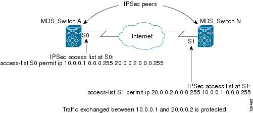
In Figure 35-2, each switch uses the key of the other switch to authenticate the identity of the other switch; this authentication always occurs when IPsec traffic is exchanged between the two switches.
If you have multiple Cisco MDS switches in a mesh topology and wish to exchange IPsec traffic passing among all of those switches, you must first configure shared keys or RSA public keys among all of those switches.
Figure 35-2 Two IPsec Switches Without CAs and Digital Certificates
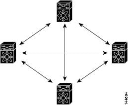
Every time a new switch is added to the IPsec network, you must configure keys between the new switch and each of the existing switches. (In Figure 35-3, four additional two-part key configurations are required to add a single encrypting switch to the network.)
Consequently, the more devices that require IPsec services, the more involved the key administration becomes. This approach does not scale well for larger, more complex encrypting networks.
Figure 35-3 Four IPsec Switches Without a CA and Digital Certificates
Implementing IPsec with CAs and Digital Certificates
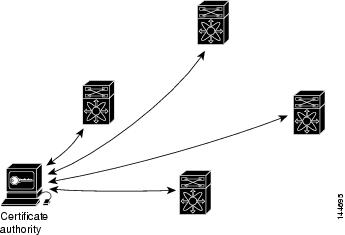
With CA and digital certificates, you do not have to configure keys between all the encrypting switches. Instead, you individually enroll each participating switch with the CA, requesting a certificate for the switch. When this has been accomplished, each participating switch can dynamically authenticate all the other participating switches. When two devices want to communicate, they exchange certificates and digitally sign data to authenticate each other. When a new device is added to the network, you simply enroll that device with a CA, and none of the other devices needs modification. When the new device attempts an IPsec connection, certificates are automatically exchanged and the device can be authenticated.
Figure 35-4 shows the process of dynamically authenticating the devices.
Figure 35-4 Dynamically Authenticating Devices with a CA
To add a new IPsec switch to the network, you need only configure that new switch to request a certificate from the CA, instead of making multiple key configurations with all the other existing IPsec switches.
How CA Certificates Are Used by IPsec Devices
When two IPsec switches want to exchange IPsec-protected traffic passing between them, they must first authenticate each other—otherwise, IPsec protection cannot occur. The authentication is done with IKE.
IKE can use two methods to authenticate the switches, using preshared keys without a CA and using RSA key-pairs with a CA. Both methods require that keys must be preconfigured between the two switches.
Without a CA, a switch authenticates itself to the remote switch using either RSA-encrypted preshared keys.
With a CA, a switch authenticates itself to the remote switch by sending a certificate to the remote switch and performing some public key cryptography. Each switch must send its own unique certificate that was issued and validated by the CA. This process works because the certificate of each switch encapsulates the public key of the switch, each certificate is authenticated by the CA, and all participating switches recognize the CA as an authenticating authority. This scheme is called IKE with an RSA signature.
Your switch can continue sending its own certificate for multiple IPsec sessions, and to multiple IPsec peers until the certificate expires. When the certificate expires, the switch administrator must obtain a new one from the CA.
CAs can also revoke certificates for devices that will no longer participate in IPsec. Revoked certificates are not recognized as valid by other IPsec devices. Revoked certificates are listed in a certificate revocation list (CRL), which each peer may check before accepting a certificate from another peer.
Certificate support for IKE has the following considerations:
•
•
•
•
•
•
•
•
Configuring IPsec Using FCIP Wizard
Fabric Manager simplifies the configuration of IPsec and IKE by enabling and configuring these features as part of the FCIP configuration using the FCIP Wizard. See the "Using the FCIP Wizard" section on page 48-8.
To enable IPsec using the FCIP Wizard in Fabric Manager, follow these steps:
Step 1
Figure 35-5 FCIP Wizard
Step 2
Note
Step 3
Step 4
Figure 35-6 Enabling IPsec on an FCIP Link
Step 5
Step 6
Step 7
Step 8
Step 9
Step 10
Step 11
To verify that IPsec and IKE are enabled using Fabric Manager, follow these steps:
Step 1
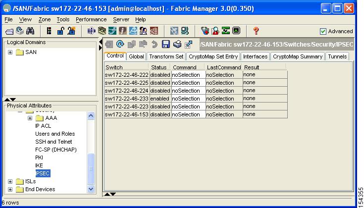
You see the IPsec configuration in the Information pane in Figure 35-7.
Figure 35-7 IPSec Configuration
Step 2
Step 3
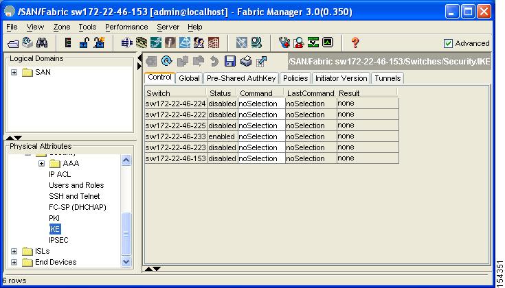
You see the IKE configuration in the Information pane shown in Figure 35-8.
Figure 35-8 IKE Configuration
Step 4
Manually Configuring IPsec and IKE
This section describes how to manually configure IPsec and IKE if you are not using the FCIP Wizard. See Configuring IPsec Using FCIP Wizard.
IPsec provides secure data flows between participating peers. Multiple IPsec data flows can exist between two peers to secure different data flows, with each tunnel using a separate set of SAs.
After you have completed IKE configuration, configure IPsec.
To configure IPsec in each participating IPsec peer, follow these steps:
Step 1
Step 2
Step 3
Step 4
This section contains the following topics:
About IKE Initialization
The IKE feature must first be enabled and configured so the IPsec feature can establish data flow with the required peer. Fabric Manager initializes IKE when you first configure it.
You cannot disable IKE if IPsec is enabled. If you disable the IKE feature, the IKE configuration is cleared from the running configuration.
About the IKE Domain
You must apply the IKE configuration to an IPsec domain to allow traffic to reach the supervisor module in the local switch. Fabric Manager sets the IPsec domain automatically when you configure IKE.
About IKE Tunnels
An IKE tunnel is a secure IKE session between two endpoints. IKE creates this tunnel to protect IKE messages used in IPsec SA negotiations.
Two versions of IKE are used in the Cisco SAN-OS implementation.
•
•
About IKE Policy Negotiation
To protect IKE negotiations, each IKE negotiation begins with a common (shared) IKE policy. An IKE policy defines a combination of security parameters to be used during the IKE negotiation. By default, no IKE policy is configured. You must create IKE policies at each peer. This policy states which security parameters will be used to protect subsequent IKE negotiations and mandates how peers are authenticated. You can create multiple, prioritized policies at each peer to ensure that at least one policy will match a remote peer's policy.
You can configure the policy based on the encryption algorithm (DES, 3DES, or AES), the hash algorithm (SHA or MD5), and the DH group (1, 2, or 5). Each policy can contain a different combination of parameter values. A unique priority number identifies the configured policy. This number ranges from 1 (highest priority) to 255 (lowest priority). You can create multiple policies in a switch. If you need to connect to a remote peer, you must ascertain that at least one policy in the local switch contains the identical parameter values configured in the remote peer. If several policies have identical parameter configurations, the policy with the lowest number is selected.
Table 35-1 provides a list of allowed transform combinations.
The following table lists the supported and verified settings for IPsec and IKE encryption authentication algorithms on the Microsoft Windows and Linux platforms:
Note
When the IKE negotiation begins, IKE looks for an IKE policy that is the same on both peers. The peer that initiates the negotiation will send all its policies to the remote peer, and the remote peer will try to find a match. The remote peer looks for a match by comparing its own highest priority policy against the other peer's received policies. The remote peer checks each of its policies in order of its priority (highest priority first) until a match is found.
A match is found when the two peers have the same encryption, hash algorithm, authentication algorithm, and DH group values. If a match is found, IKE completes the security negotiation and the IPsec SAs are created.
If an acceptable match is not found, IKE refuses negotiation and the IPsec data flows will not be established.
Configuring an IKE Policy
To configure the IKE policy negotiation parameters using Fabric Manager, follow these steps:
Step 1
You see the IKE configuration in the Information pane in Figure 35-9.
Figure 35-9 IKE Configuration
Step 2
You see the existing IKE polices in the Information pane.
Step 3
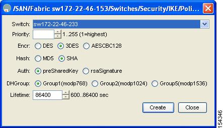
You see the Create Policy dialog box shown in Figure 35-10.
Figure 35-10 Create IKE
Step 4
Step 5
Step 6
Step 7
Note
Optional IKE Parameter Configuration
You can optionally configure the following parameters for the IKE feature:
•
•
•
–
–
Note
Caution
Tip
Note
This section includes the following topics:
•
•
•
Configuring the Keepalive Time for a Peer
To configure the keepalive time for each peer using Fabric Manager, follow these steps:
Step 1
You see the IKE configuration in the Information pane (see Figure 35-11).
Figure 35-11 IKE Configuration
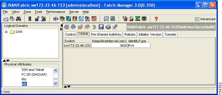
Step 2
You see the global statistics of a specific IKE protocol in the Information pane (see Figure 35-12).
Figure 35-12 IKE Global Tab Information
Step 3
Step 4
Configuring the Initiator Version
To configure the initiator version using Fabric Manager, follow these steps:
Step 1
You see the IKE configuration in the Information pane (see Figure 35-13).
Figure 35-13 IKE Configuration
Step 2
You see the existing initiator versions for the peers in the Information pane.
Step 3
You see the Create Initiator Version dialog box shown in Figure 35-14.
Figure 35-14 Create Initiator Version Dialog Box
Step 4
Step 5
IKEv1 represents the IKE protocol version used when connecting to a remote peer.
Step 6
Clearing IKE Tunnels or Domains
If an IKE tunnel ID is not specified for the IKE configuration, you can clear all existing IKE domain connections.
To clear all the IKE Tunnels or Domains using Fabric Manager, follow these steps:
Step 1
You see the IKE configuration in the Information pane (see Figure 35-15).
Figure 35-15 IKE Configuration
Step 2
You see the IKE tunnels.
Step 3
Refreshing SAs
To refresh the SAs after changing the IKEv2 configuration using Fabric Manager, follow these steps:
Step 1
You see the IKE configuration shown in Figure 35-16.
Figure 35-16 IKE Configuration
Step 2
Step 3
Crypto IPv4-ACLs
IP access control lists (IPv4-ACLs) provide basic network security to all switches in the Cisco MDS 9000 Family. IPv4 IP-ACLs restrict IP-related traffic based on the configured IP filters. See Chapter 33, "Configuring IPv4 and IPv6 Access Control Lists" for details on creating and defining IPv4-ACLs.
In the context of crypto maps, IPv4-ACLs are different from regular IPv4-ACLs. Regular IPv4-ACLs determine what traffic to forward or block at an interface. For example, IPv4-ACLs can be created to protect all IP traffic between subnet A and subnet Y or Telnet traffic between host A and host B.
This section contains the following topics:
•
•
•
•
•
•
About Crypto IPv4-ACLs
Crypto IPv4-ACLs are used to define which IP traffic requires crypto protection and which traffic does not.
Crypto IPv4-ACLs associated with IPsec crypto map entries have four primary functions:
•
•
•
•
Tip
Note
Crypto IPv4-ACL Guidelines
Follow these guidelines when configuring IPv4-ACLs for the IPsec feature:
•
•
–
–
Note
•
Note
•
•
•
•
•
•
•
–
–
For traffic from 20.0.0.2 to 10.0.0.1, that same IPv4-ACL entry on switch A is evaluated as follows:
–
–
Figure 35-17 IPsec Processing of Crypto IPv4-ACLs
•
•
•
Mirror Image Crypto IPv4-ACLs
For every crypto IPv4-ACL specified for a crypto map entry defined at the local peer, define a mirror image crypto IPv4-ACL at the remote peer. This configuration ensures that IPsec traffic applied locally can be processed correctly at the remote peer.
Tip
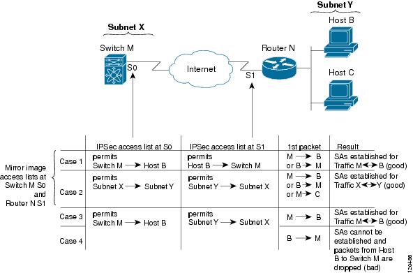
Figure 35-18 shows some sample scenarios with and without mirror image IPv4-ACLs.
Figure 35-18 IPsec Processing of Mirror Image Configuration
As Figure 35-18 indicates, IPsec SAs can be established as expected whenever the two peers' crypto IPv4-ACLs are mirror images of each other. However, an IPsec SA can be established only some of the time when the IPv4-ACLs are not mirror images of each other. This can happen in the case when an entry in one peer's IPv4-ACL is a subset of an entry in the other peer's IPv4-ACL, such as shown in cases 3 and 4 of Figure 35-18. IPsec SA establishment is critical to IPsec. Without SAs, IPsec does not work, causing any packets matching the crypto IPv4-ACL criteria to be silently dropped instead of being forwarded with IPsec security.
In case 4, an SA cannot be established because SAs are always requested according to the crypto IPv4-ACLs at the initiating packet's end. In case 4, router N requests that all traffic between subnet X and subnet Y be protected, but this is a superset of the specific flows permitted by the crypto IPv4-ACL at switch M so the request is not permitted. Case 3 works because switch M's request is a subset of the specific flows permitted by the crypto IPv4-ACL at router N.
Because of the complexities introduced when crypto IPv4-ACLs are not configured as mirror images at peer IPsec devices, we strongly encourage you to use mirror image crypto IPv4-ACLs.
The any Keyword in Crypto IPv4-ACLs
Tip
The any keyword in a permit statement is discouraged when you have multicast traffic flowing through the IPsec interface. This configuration can cause multicast traffic to fail.
The permit any statement causes all outbound traffic to be protected (and all protected traffic sent to the peer specified in the corresponding crypto map entry) and requires protection for all inbound traffic. Then, all inbound packets that lack IPsec protection are silently dropped, including packets for routing protocols, NTP, echo, echo response, and so forth.
You need to be sure you define which packets to protect. If you must use any in a permit statement, you must preface that statement with a series of deny statements to filter out any traffic (that would otherwise fall within that permit statement) that you do not want to be protected.
Creating Crypto IPv4-ACLs
To create crypto IPv4-ACLs refer to the Cisco MDS 9000 Family CLI Configuration Guide.
About Transform Sets in IPsec
A transform set represents a certain combination of security protocols and algorithms. During the IPsec security association negotiation, the peers agree to use a particular transform set for protecting a particular data flow.
You can specify multiple transform sets, and then specify one or more of these transform sets in a crypto map entry. The transform set defined in the crypto map entry is used in the IPsec security association negotiation to protect the data flows specified by that crypto map entry's access list.
During IPsec security association negotiations with IKE, the peers search for a transform set that is the same at both peers. When such a transform set is found, it is selected and applied to the protected traffic as part of both peers' IPsec security associations.
Tip
Note
Table 35-2 provides a list of allowed transform combinations for IPsec.
Table 35-2 IPsec Transform Configuration Parameters
encryption algorithm
56-bit DES-CBC
168-bit DES
128-bit AES-CBC
128-bit AES-CTR1
256-bit AES-CBC
256-bit AES-CTR1
esp-des
esp-3des
esp-aes 128
esp-aes 128 ctr
esp-aes 256
esp-aes 256 ctr
hash/authentication algorithm1 (optional)
SHA-1 (HMAC variant)
MD5 (HMAC variant)
AES-XCBC-MAC
esp-sha1-hmac
esp-md5-hmac
esp-aes-xcbc-mac
1 If you configure the AES counter (CTR) mode, you must also configure the authentication algorithm.
Note
Configuring Transform Sets
To configure transform sets using Fabric Manager, follow these steps:
Step 1
You see the IPSec configuration shown in Figure 35-19.
Figure 35-19 IPsec Configuration
Step 2
Step 3
You see the Create IPSEC dialog box shown in Figure 35-20.
Figure 35-20 Create IPSEC
Step 4
Step 5
Step 6
Step 7
About Crypto Map Entries
Once you have created the crypto IPv4-ACLs and transform sets, you can create crypto map entries that combine the various parts of the IPsec SA, including the following:
•
•
•
•
•
•
Crypto map entries with the same crypto map name (but different map sequence numbers) are grouped into a crypto map set.
When you apply a crypto map set to an interface, the following events occur:
•
•
If a crypto map entry sees outbound IP traffic that requires protection, an SA is negotiated with the remote peer according to the parameters included in the crypto map entry.
The policy derived from the crypto map entries is used during the negotiation of SAs. If the local switch initiates the negotiation, it will use the policy specified in the crypto map entries to create the offer to be sent to the specified IPsec peer. If the IPsec peer initiates the negotiation, the local switch checks the policy from the crypto map entries and decides whether to accept or reject the peer's request (offer).
For IPsec to succeed between two IPsec peers, both peers' crypto map entries must contain compatible configuration statements.
SA Establishment Between Peers
When two peers try to establish an SA, they must each have at least one crypto map entry that is compatible with one of the other peer's crypto map entries.
For two crypto map entries to be compatible, they must at least meet the following criteria:
•
•
•
seq-numof each map entry to rank the map entries: the lower theseq-num, the higher the priority. At the interface that has the crypto map set, traffic is evaluated against higher priority map entries first.•
When a packet matches a permit entry in a particular IPv4-ACL, the corresponding crypto map entry is tagged, and the connections are established.
Crypto Map Configuration Guidelines
When configuring crypto map entries, follow these guidelines:
•
•
•
•
Creating Crypto Map Entries
To create mandatory crypto map entries using Fabric Manager, follow these steps:
Step 1
You see the IPSec configuration in the Information pane (see Figure 35-21).
Figure 35-21 IPsec Configuration
Step 2
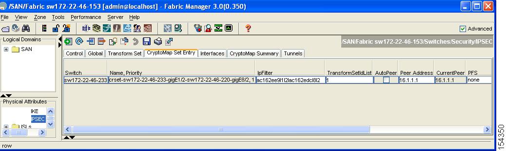
You see the existing crypto maps configured (see Figure 35-22).
Figure 35-22 Existing Crypto Maps
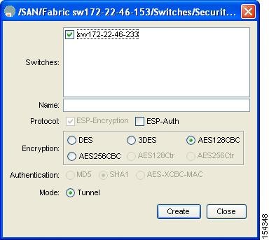
Step 3
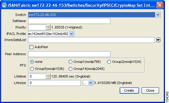
You see the Create Crypto Map dialog box shown in Figure 35-23.
Figure 35-23 Create Crypto Map Dialog Box
Step 4
Step 5
Step 6
Step 7
Step 8
Step 9
About SA Lifetime Negotiation
You can override the global lifetime values (size and time) by configuring an SA-specific lifetime value.
To specify SA lifetime negotiation values, you can optionally configure the lifetime value for a specified crypto map. If you do, this value overrides the globally set values. If you do not specify the crypto map specific lifetime, the global value (or global default) is used.
See the "Global Lifetime Values" section for more information on global lifetime values.
Setting the SA Lifetime
To set the SA lifetime for a specified crypto map entry using Fabric Manager, follow these steps:
Step 1
You see the IP SEC configuration in the Information pane (see Figure 35-24).
Figure 35-24 IPsec Configuration
Step 2
You see the existing crypto maps configured (see Figure 35-25).
Figure 35-25 Existing Crypto Maps - Leftmost Columns
Step 3
You see more columns shown in Figure 35-26.
Figure 35-26 Existing Crypto Maps - Rightmost Columns
Step 4
Step 5
About the AutoPeer Option
Setting the peer address as AutoPeer in the crypto map indicates that the destination endpoint of the traffic should be used as the peer address for the SA. Using the same crypto map, a unique SA can be set up at each of the endpoints in the subnet specified by the crypto map's IPv4-ACL entry. Auto-peer simplifies configuration when traffic endpoints are IPsec capable. It is particularly useful for iSCSI, where the iSCSI hosts in the same subnet do not require separate configuration.
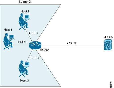
Figure 35-27 shows a scenario where the auto-peer option can simplify configuration. Using the auto-peer option, only one crypto map entry is needed for all the hosts from subnet X to set up SAs with the switch. Each host will set up its own SA, but will share the crypto map entry. Without the auto-peer option, each host needs one crypto map entry.
Figure 35-27 iSCSI with End-to-End IPsec Using the auto-peer Option
Configuring the AutoPeer Option
To configure the AutoPeer option using Fabric Manager, follow these steps:
Step 1
You see the IPsec configuration in the Information pane (see Figure 35-28).
Figure 35-28 IPsec Configuration
Step 2
You see the existing crypto maps configured in Figure 35-29.
Figure 35-29 Existing Crypto Maps
Step 3
Step 4
About Perfect Forward Secrecy
To specify SA lifetime negotiation values, you can also optionally configure the perfect forward secrecy (PFS) value in the crypto map.
The PFS feature is disabled by default. If you set the PFS group, you can set one of the DH groups: 1, 2, 5, or 14. If you do not specify a DH group, the software uses group 1 by default.
Configuring Perfect Forward Secrecy
To configure the PFS value using Fabric Manager, follow these steps:
Step 1
You see the IPsec configuration in the Information pane (see Figure 35-30).
Figure 35-30 IPsec Configuration
Step 2
You see the existing crypto maps configured in Figure 35-31.
Figure 35-31 Existing Crypto Maps
Step 3
Step 4
About Crypto Map Set Application
You need to apply a crypto map set to each interface through which IPsec traffic will flow. Applying the crypto map set to an interface instructs the switch to evaluate all the interface's traffic against the crypto map set and to use the specified policy during connection or SA negotiation on behalf of the traffic to be protected by crypto.
You can apply only one crypto map set to an interface. You can apply the same crypto map to multiple interfaces. However, you cannot apply more than one crypto map set to each interface.
Applying a Crypto Map Set
To apply a crypto map set to an interface using Fabric Manager, follow these steps:
Step 1
You see the IPsec configuration in the Information pane (see Figure 35-32).
Figure 35-32 IPsec Configuration
Step 2
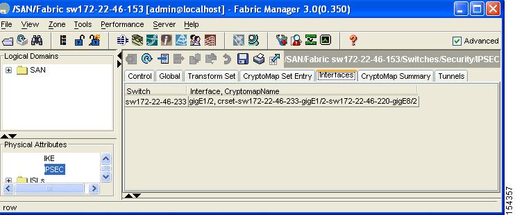
You see the existing interface to crypto map configuration in Figure 35-33.
Figure 35-33 Crypto Map Interfaces
Step 3
Step 4
Step 5
IPsec Maintenance
Certain configuration changes will only take effect when negotiating subsequent security associations. If you want the new settings to take immediate effect, you must clear the existing security associations so that they will be reestablished with the changed configuration. If the switch is actively processing IPsec traffic, it is desirable to clear only the portion of the security association database that would be affected by the configuration changes (that is, clear only the security associations established by a given crypto map set). Clearing the full security association database should be reserved for large-scale changes, or when the router is processing very little other IPsec traffic.
Global Lifetime Values
If you have not configured a lifetime in the crypto map entry, the global lifetime values are used when negotiating new IPsec SAs.
You can configure two lifetimes: timed or traffic-volume. An SA expires after the first of these lifetimes is reached. The default lifetimes are 3,600 seconds (one hour) and 450 GB.
If you change a global lifetime, the new lifetime value will not be applied to currently existing SAs, but will be used in the negotiation of subsequently established SAs. If you wish to use the new values immediately, you can clear all or part of the SA database.
Assuming that the particular crypto map entry does not have lifetime values configured, when the switch requests new SAs it will specify its global lifetime values in the request to the peer; it will use this value as the lifetime of the new SAs. When the switch receives a negotiation request from the peer, it uses the value determined by the IKE version in use:
•
•
The SA (and corresponding keys) will expire according to whichever comes sooner, either after the specified amount of time (in seconds) has passed or after the specified amount of traffic (in bytes) has passed.
A new SA is negotiated before the lifetime threshold of the existing SA is reached to ensure that negotiation completes before the existing SA expires.
The new SA is negotiated when one of the following thresholds is reached (whichever comes first):
•
•
If no traffic has passed through when the lifetime expires, a new SA is not negotiated. Instead, a new SA will be negotiated only when IPsec sees another packet that should be protected.
To configure global SA lifetimes using Fabric Manager, follow these steps:
Step 1
Step 2
Step 3
Step 4
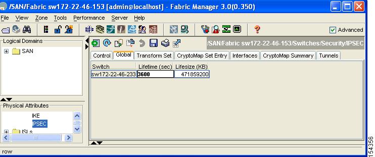
Figure 35-34 IP Sec Configuration Global Tab
Step 5
Default Settings
Table 35-3 lists the default settings for IKE parameters.
Table 35-4 lists the default settings for IPsec parameters.