-
Cisco MDS 9000 Family Fabric Manager Configuration Guide, Release 3.4(1a)
-
Index
-
New and Changed Information
-
Preface
- Getting Started
- Installation and Switch Management
- Switch Configuration
-
Fabric Configuration
-
Configuring and Managing VSANs
-
SAN Device Virtualization
-
Creating Dynamic VSANs
-
Configuring Inter-VSAN Routing
-
Configuring and Managing Zones
-
Distributing Device Alias Services
-
Configuring Fibre Channel Routing Services and Protocols
-
Dense Wavelength Division Multiplexing
-
Managing FLOGI, Name Server, FDMI, and RSCN Databases
-
Discovering SCSI Targets
-
Configuring FICON
-
Advanced Features and Concepts
-
-
Security
-
Configuring FIPS
-
Configuring Users and Common Roles
-
Configuring SNMP
-
Configuring RADIUS and TACACS+
-
Configuring IPv4 Access Control Lists
-
Configuring Certificate Authorities and Digital Certificates
-
Configuring IPsec Network Security
-
Configuring FC-SP and DHCHAP
-
Configuring Port Security
-
Configuring Fabric Binding
-
- IP Services
- Intelligent Storage Services
- Network and Switch Monitoring
- Traffic Management
- Troubleshooting
-
Launching Fabric Manager in Cisco SAN-OS Releases Prior to 3.2(1)
-
Cisco Fabric Manager Unsupported Feature List
-
Interface Nonoperational Reason Codes
-
Managing Cisco FabricWare
-
Configuration Limits for Cisco MDS SAN-OS Release 3.1(x) and 3.2(x)
-
 Feedback
Table Of Contents
Call Home Configuration Process
Customized Alert Group Messages
Call Home Message Level Feature
Configuring General E-Mail Options
Periodic Inventory Notification
Call Home Configuration Distribution
Sample Syslog Alert Notification in Full-txt Format
Sample Syslog Alert Notification in XML Format
Sample RMON Notification in XML Format
Configuring Call Home
Call Home provides e-mail-based notification of critical system events. A versatile range of message formats are available for optimal compatibility with pager services, standard e-mail, or XML-based automated parsing applications. Common uses of this feature may include direct paging of a network support engineer, e-mail notification to a Network Operations Center, and utilization of Cisco AutoNotify services for direct case generation with the Technical Assistance Center.
The Call Home feature provides message throttling capabilities. Periodic inventory messages, port syslog messages, and RMON alert messages are added to the list of deliverable Call Home messages. If required you can also use the Cisco Fabric Services application to distribute the Call Home configuration to all other switches in the fabric.
This chapter includes the following sections:
•
Call Home Configuration Process
•
•
•
•
•
Call Home Features
The Call Home functionality is available directly through the Cisco MDS 9000 Family. It provides multiple Call Home profiles (also referred to as Call Home destination profiles), each with separate potential destinations. You can define your own destination profiles in addition to predefined profiles.
The Call Home function can even leverage support from Cisco Systems or another support partner. Flexible message delivery and format options make it easy to integrate specific support requirements.
The Call Home feature offers the following advantages:
•
•
•
–
–
–
•
•
Cisco AutoNotify
For those who have service contracts directly with Cisco Systems, automatic case generation with the Technical Assistance Center is possible by registering with the AutoNotify service. AutoNotify provides fast time to resolution of system problems by providing a direct notification path to Cisco customer support.
The AutoNotify feature requires several Call Home parameters to be configured, including certain contact information, e-mail server, and an XML destination profile as specified in the Service Activation document found on the Cisco.com web site at: http://www.cisco.com/univercd/cc/td/doc/product/voice/c_callmg/3_3/service/serv332/ccmsrvs/sssrvact.htm
To configure a Cisco MDS 9000 Family switch to use the AutoNotify service, an XML destination profile must be configured to send messages to Cisco. Specific setup, activation, and e-mail address information is found on the Cisco.com web site at: http://www.cisco.com/en/US/partner/products/hw/ps4159/ps4358/products_configuration_example09186a0080108e72.shtml
To register, the following items are required:
•
•
•
•
The ContractID, CustomerID, SiteID, and SwitchPriority parameters are not required by the AutoNotify feature. They are only intended to be used as additional information by Cisco customers and service partners.
Call Home Configuration Process
The actual configuration of Call Home depends on how you intend to use the feature. Some points to consider include:
•
•
•
•
•
To configure Call Home, follow these steps:
Step 1
Step 2
Step 3
Step 4
Step 5
Step 6
Contact Information
It is mandatory for each switch to include e-mail, phone, and street address information. It is optional to include the contract ID, customer ID, site ID, and switch priority information.
To assign the contact information using Fabric Manager, follow these steps:
Step 1
You see the Call Home tabs in the Information pane (see Figure 64-1).
Figure 64-1 Call Home in Fabric Manager
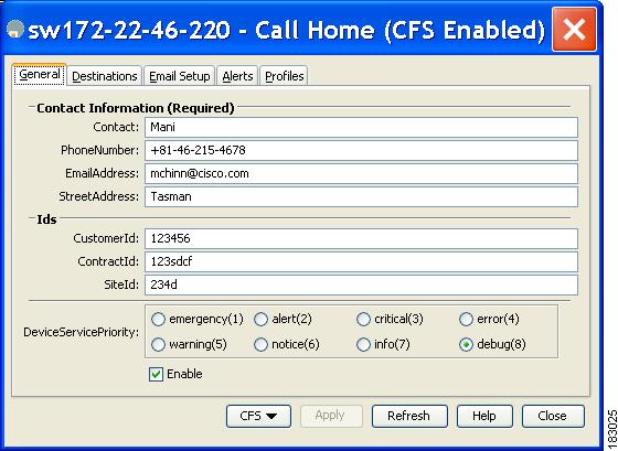
Step 2
Figure 64-2 Call Home in Device Manager
Step 3
Step 4
Note
Step 5
Step 6
Destination Profiles
A destination profile contains the required delivery information for an alert notification. Destination profiles are typically configured by the network administrator. At least one destination profile is required. You can configure multiple destination profiles of one or more types.
You can use one of the predefined destination profiles or define a desired profile. If you define a new profile, you must assign a profile name.
Note
You can configure the following attributes for a destination profile:
•
•
•
To configure predefined destination profile messaging options using Fabric Manager, follow these steps:
Step 1
Step 2
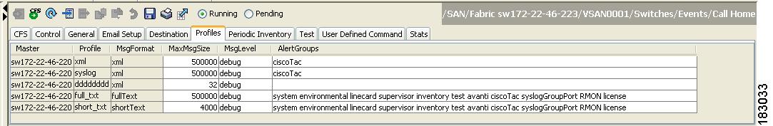
You see the Call Home profiles for multiple switches shown in Figure 64-3.
Figure 64-3 Call Home Profiles for Multiple Switches
Step 3
Step 4
Step 5
To configure a new destination-profile (and related parameters) using Fabric Manager, follow these steps:
Step 1
Step 2
You see Call Home profiles for multiple switches.
Figure 64-4 Call Home Profiles for Multiple Switches
Step 3
Step 4
Step 5
Step 6
Alert Groups
An alert group is a predefined subset of Call Home alerts supported in all switches in the Cisco MDS 9000 Family. Different types of Call Home alerts are grouped into different alert groups depending on their type. You can associate one or more alert groups to each profile as required by your network.
The alert group feature allows you to select the set of Call Home alerts to be received by a destination profile (either predefined or user-defined). You can associate multiple alert groups with a destination profile.
Note
To associate an alert group with a destination profile using Fabric Manager, follow these steps:
Step 1
Step 2
You see the Call Home profiles for multiple switches shown in Figure 64-5.
Figure 64-5 Call Home Profiles for Multiple Switches
Step 3
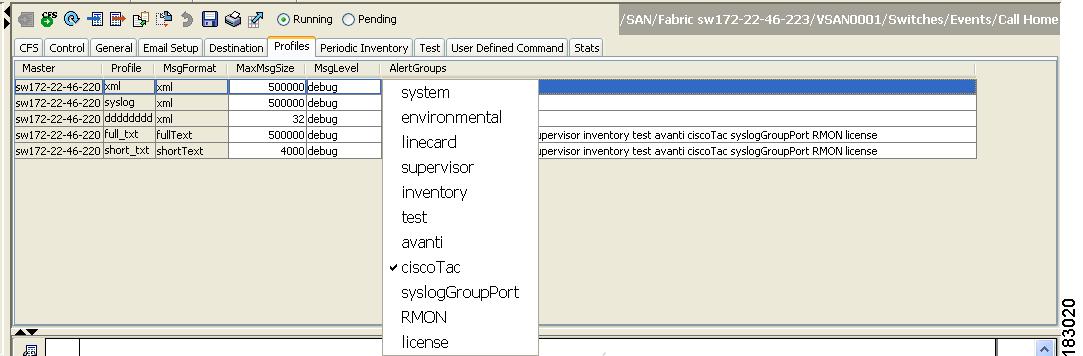
You see the alert groups drop-down menu shown in Figure 64-6.
Figure 64-6 Alert Groups Drop-down Menu
Step 4
Step 5
Step 6
Customized Alert Group Messages
The predefined Call Home alert groups generate notification messages when certain events occur on the switch. You can customize predefined alert groups to execute additional valid show commands when specific events occur. The output from these additional show commands is included in the notification message along with that of the predefined show commands.
Note
Note
To assign show commands to be executed when an alert is sent, you must associate the commands with the alert group. When an alert is sent, Call Home associates the alert group with an alert type and attaches the output of the show commands to the alert message.
Note
To customize Call Home alert group messages using Fabric Manager, follow these steps:
Step 1
Step 2
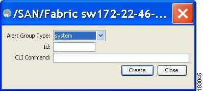
You see the User Defined Command information shown in Figure 64-7.
Figure 64-7 User Defined Command Dialog Box
Step 3
Step 4
Step 5
Step 6
Step 7
Step 8
Step 9
Step 10
Call Home Message Level Feature
The Call Home message level feature allows you to filter messages based on their level of urgency. Each destination profile (predefined and user-defined) is associated with a Call Home message level threshold. Any message with a value lower that the urgency threshold is not sent. The urgency level ranges from 0 (lowest level of urgency) to 9 (highest level of urgency), and the default is 0 (all messages are sent).
Note
To set the message level for each destination profile for Call Home using Fabric Manager, follow these steps:
Step 1
You see the Call Home information in the Information pane.
In Device Manager, choose Admin > Events > Call Home.
Step 2
You see the Call Home profiles shown in Figure 64-8.
Figure 64-8 Call Home Profiles
Step 3
Step 4
Syslog-Based Alerts
You can configure the switch to send certain syslog messages as Call Home messages. The syslog-group-port alert group selects syslog messages for the port facility. The Call Home application maps the syslog severity level to the corresponding Call Home severity level (see the "Call Home Message Levels" section). For example, if you select level 5 for the Call Home message level, syslog messages at levels 0, 1, and 2 are included in the Call Home log.
Whenever a syslog message is generated, the Call Home application sends a Call Home message depending on the mapping between the destination profile and the alert group mapping and based on the severity level of the generated syslog message. To receive a syslog-based Call Home alert, you must associate a destination profile with the syslog alert groups (currently there is only one syslog alert group—syslog-group-port) and configure the appropriate message level (see the "Call Home Message Level Feature" section).
Note
To configure the syslog-group-port alert group using Fabric Manager, follow these steps:
Step 1
Step 2
You see the Call Home information in the Information pane.
Step 3
You see the Call Home profiles shown in Figure 64-9.
Figure 64-9 Call Home Profiles
Step 4
You see the Create Call Home Profile dialog box.
Step 5
Step 6
Step 7
Step 8
Step 9
Step 10
RMON-Based Alerts
You can configure the switch to send Call Home notifications corresponding to RMON alert triggers. All RMON-based Call Home messages have their message level set to NOTIFY (2). The RMON alert group is defined for all RMON-based Call Home alerts. To receive an RMON-based Call Home alert, you must associate a destination profile with the RMON alert group.
To configure RMON alert groups using Fabric Manager, follow these steps:
Step 1
Step 2
You see the Call Home information in the Information pane.
Step 3
You see the Call Home profiles shown in Figure 64-10.
Figure 64-10 Call Home Profiles
Step 4
You see the Create Call Home Profile dialog box.
Step 5
Step 6
Step 7
Step 8
Step 9
Step 10
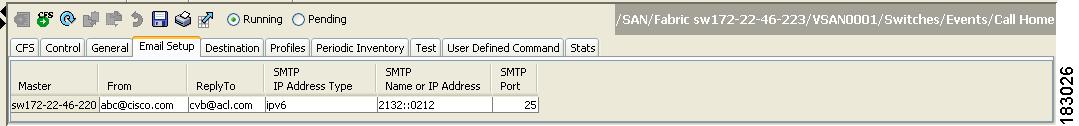
E-Mail Options
You can configure the from, reply-to, and return-receipt e-mail addresses. While most e-mail address configurations are optional, you must configure the SMTP server address for the Call Home functionality to work.
Configuring General E-Mail Options
To configure general e-mail options using Fabric Manager, follow these steps:
Step 1
Step 2
You see the Call Home information in the Information pane.
Step 3
Figure 64-11 Call Home Email Setup Tab
Step 4
Step 5
Step 6
Step 7
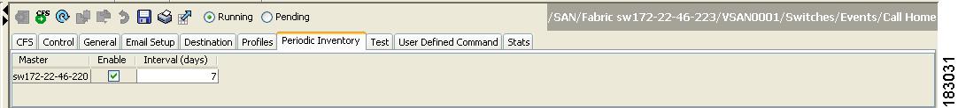
Periodic Inventory Notification
You can configure the switch to periodically send a message with an inventory of all the software services currently enabled and running on the switch along with hardware inventory information. The inventory is modified each time the switch is restarted nondisruptively.
By default, this feature is disabled in all switches in the Cisco MDS 9000 Family. When you enable this feature without configuring an interval value, the Call Home message is sent every 7 days. This value ranges from 1 to 30 days.
To enable periodic inventory notification in a Cisco MDS 9000 Family switch using Fabric Manager, follow these steps:
Step 1
Step 2
You see the Call Home information in the Information pane.
Step 3
You see the Call Home periodic inventory information shown in Figure 64-12.
Figure 64-12 Call Home Periodic Inventory Tab
Step 4
Step 5
Step 6
Step 7
Duplicate Message Throttle
You can configure a throttling mechanism to limit the number of Call Home messages received for the same event. If the same message is sent multiple times from the switch within a short period of time, you may be swamped with a large number of duplicate messages.
By default, this feature is enabled in all switches in the Cisco MDS 9000 Family. When enabled, if the number of messages sent exceeds the maximum limit of 30 messages within the 2-hour time frame, then further messages for that alert type are discarded within that time frame. You cannot modify the time frame or the message counter limit.
If 2 hours have elapsed since the first such message was sent and a new message has to be sent, then the new message is sent and the time frame is reset to the time when the new message was sent and the count is reset to 1.
To enable message throttling in a Cisco MDS 9000 Family switch using Fabric Manager, follow these steps:
Step 1
Step 2
You see the Call Home information in the Information pane.
Step 3
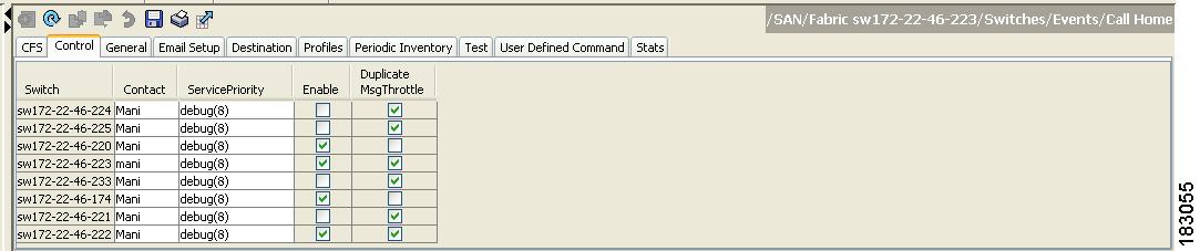
You see the information shown in Figure 64-13.
Figure 64-13 Call Home Control Tab
Step 4
Step 5
Step 6
Call Home Enable Function
Once you have configured the contact information, you must enable the Call Home function.
To enable the Call Home function using Fabric Manager, follow these steps:
Step 1
Step 2
You see the Call Home information in the Information pane.
Step 3
You see the information shown in Figure 64-14.
Figure 64-14 Call Home Control Tab
Step 4
Step 5
Step 6
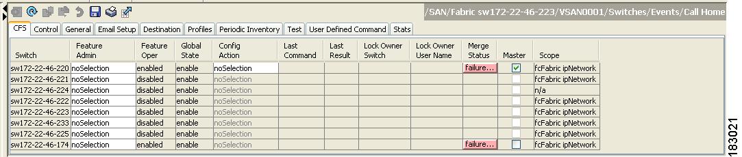
Call Home Configuration Distribution
You can enable fabric distribution for all Cisco MDS switches in the fabric. When you perform Call Home configurations, and distribution is enabled, that configuration is distributed to all the switches in the fabric.
You automatically acquire a fabric-wide lock when you perform the first configuration operation after you enabled distribution in a switch. The Call Home application uses the effective and pending database model to store or commit the configuration changes. When you commit the configuration changes, the effective database is overwritten by the configuration changes in the pending database and all the switches in the fabric receive the same configuration. After making the configuration changes, you can choose to discard the changes by aborting the changes instead of committing them. In either case, the lock is released. See Chapter 13, "Using the CFS Infrastructure" for more information on the CFS application.
Note
To enable Call Home fabric distribution using Fabric Manager, follow these steps:
Step 1
Step 2
You see the Call Home information in the Information pane.
Step 3
You see the CFS information for Call Home shown in Figure 64-15.
Figure 64-15 Call Home CFS Tab
Step 4
Step 5
Step 6
Fabric Lock Override
If you have performed a Call Home task and have forgotten to release the lock by either committing or discarding the changes, an administrator can release the lock from any switch in the fabric. If the administrator performs this task, your changes to the pending database are discarded and the fabric lock is released.
Tip
Database Merge Guidelines
See the "CFS Merge Support" section on page 13-11 for detailed concepts.
When merging two Call Home databases, follow these guidelines:
•
–
–
–
•
Call Home Communications Test
To test the Call Home function and simulate a message generation using Fabric Manager, follow these steps:
Step 1
Step 2
You see the Call Home information in the Information pane.
Step 3
You see the configured tests for the switch and the status of the last testing.
Step 4
Step 5
Step 6
Configuring EMC Call Home
This feature is configured using Fabric Manager Web Server or by editing the server.properties file. The documentation for configuring EMC Call Home using Fabric Manager Web Server is contained in the Web Server Admin > Configure > Preferences web page.
EMC Call Home enables notification of hardware and software failures only. If this option is disabled, then the system sends notifications of all port failures, link failures, reboots, and shutdowns.
The EMC Call Home feature requires the following:
•
•
•
Note
Table 64-1 includes all the traps for EMC Call Home.
Note
Sample Syslog Alert Notification in Full-txt Format
source:MDS9000Switch Priority:7Device Id:DS-C9506@C@FG@07120011Customer Id:basuContract Id:123Site Id:San JoseServer Id:DS-C9506@C@FG@07120011Time of Event:2004-10-08T11:10:44Message Name:SYSLOG_ALERTMessage Type:SyslogSeverity Level:2System Name:10.76.100.177Contact Name:Basavaraj BContact Email:admin@yourcompany.comContact Phone:+91-80-310-1718Street Address:#71 , Miller's RoadEvent Description:2004 Oct 8 11:10:44 10.76.100.177 %PORT-5-IF_TRUNK_UP: %$VSAN 1%$ Interface fc2/5, vsan 1 is upsyslog_facility:PORTstart chassis information:Affected Chassis:DS-C9506Affected Chassis Serial Number:FG@07120011Affected Chassis Hardware Version:0.104Affected Chassis Software Version:3.1(1)Affected Chassis Part No:73-8607-01end chassis information:Sample Syslog Alert Notification in XML Format
X-Mozilla-Status2: 02000000Return-Path: <tester@cisco.com>...<?xml version="1.0" encoding="UTF-8" standalone="no" ?><!DOCTYPE mml SYSTEM "mml10.dtd"><!--Alert:SYSLOG_ALERT--><mml><header><time>2004-09-30T06:12:36</time><name>SYSLOG_ALERT</name><type>Syslog</type><level>2</level><source>MDS9000</source><priority>7</priority><deviceId>DS-C9506@C@FOX0712S00H</deviceId><custId>911</custId><contractId>33445</contractId><siteId>91111</siteId><serverId>DS-C9506@C@FOX0712S00H</serverId></header><body><msgDesc>2004 Sep 30 06:12:36 switch186 %PORT-5-IF_UP: %$VSAN 2000%$ Interface fc1/10 is up in mode FL</msgDesc><sysName>switch186</sysName><sysContact>USA</sysContact><sysContactEmail>admin@yourcompany.com</sysContactEmail><sysContactPhoneNumber>+91-080-8888888</sysContactPhoneNumber><sysStreetAddress>91</sysStreetAddress><chassis><name>DS-C9506</name><serialNo>FOX0712S00H</serialNo><partNo>73-8697-01</partNo><hwVersion>0.104</hwVersion><swVersion>3.1(1)</swVersion></chassis><nvp><name>syslog_facility</name><value>PORT</value></nvp></body></mml>Sample RMON Notification in XML Format
Return-Path: <tester@cisco.com>...<?xml version="1.0" encoding="UTF-8" standalone="no" ?><!DOCTYPE mml SYSTEM "mml10.dtd"><!--Alert:RMON_ALERT--><mml><header><time>2004-10-12T04:59:13</time><name>RMON_ALERT</name><type>RMON</type><level>2</level><source>MDS9000</source><priority>3</priority><deviceId>DS-C9506@C@FOX0712S00H</deviceId><custId>0</custId><contractId>u</contractId><siteId>&</siteId><serverId>DS-C9506@C@FOX0712S00H</serverId></header><body><msgDesc>rlaxmina-w2k07</msgDesc><sysName>switch186</sysName><sysContact>USA</sysContact><sysContactEmail>admin@yourcompany.com</sysContactEmail><sysContactPhoneNumber>+91-080-000000</sysContactPhoneNumber><sysStreetAddress>91</sysStreetAddress><chassis><name>DS-C9506</name><serialNo>FOX0712S00H</serialNo><partNo>73-8697-01</partNo><hwVersion>0.104</hwVersion><swVersion>3.1(1)</swVersion></chassis><nvp><name>ThresholdType</name><value>RisingThreshold</value></nvp><nvp><name>ThresholdValue</name><value>0</value></nvp><nvp><name>AlarmValue</name><value>0</value></nvp></body></mml>Default Settings
Table 64-2 lists the default Call Home settings.
Event Triggers
This section discusses Call Home trigger events. Trigger events are divided into categories, with each category assigned CLI commands to execute when the event occurs. The command output is included in the transmitted message. Table 64-3 lists the trigger events.
Table 64-4 lists event categories and command outputs.
Call Home Message Levels
Call Home messages (sent for syslog alert groups) have the syslog severity level mapped to the Call Home message level (see the "Syslog-Based Alerts" section).
This section discusses the severity levels for a Call Home message when using one or more switches in the Cisco MDS 9000 Family. Call Home message levels are preassigned per event type.
Severity levels range from 0 to 9, with 9 having the highest urgency. Each syslog level has keywords and a corresponding syslog level as listed in Table 64-5.
Note
Note
Message Contents
The following contact information can be configured on the switch:
•
•
•
•
•
•
Table 64-6 describes the short text formatting option for all message typesFigure 64-15.
Table 64-7, Table 64-8, and Table 64-9 display the information contained in plain text and XML messages.
Table 64-7 Reactive Event Message Format
(Plain text and XML)
(Plain text and XML)
(XML only)Time stamp
Date and time stamp of event in ISO time notation: YYYY-MM-DDTHH:MM:SS.
Note
/mml/header/time
Message name
Name of message. Specific event names are listed in the "Event Triggers" section.
/mml/header/name
Message type
Specifically "Call Home."
/mml/header/type
Message group
Specifically "reactive."
/mml/header/group
Severity level
Severity level of message (see Table 64-5).
/mml/header/level
Source ID
Product type for routing.
/mml/header/source
Device ID
Unique device identifier (UDI) for end device generating message. This field should empty if the message is non-specific to a fabric switch. Format: type@Sid@serial, where
•
•
•
•
Example: DS-C9509@C@12345678
/mml/ header/deviceId
Customer ID
Optional user-configurable field used for contract info or other ID by any support service.
/mml/ header/customerID
Contract ID
Optional user-configurable field used for contract info or other ID by any support service.
/mml/ header /contractId
Site ID
Optional user-configurable field used for Cisco-supplied site ID or other data meaningful to alternate support service.
/mml/ header/siteId
Server ID
If the message is generated from the fabric switch, it is the unique device identifier (UDI) of the switch.
Format: type@Sid@serial, where
•
•
•
•
Example: "DS-C9509@C@12345678
/mml/header/serverId
Message description
Short text describing the error.
/mml/body/msgDesc
Device name
Node that experienced the event. This is the host name of the device.
/mml/body/sysName
Contact name
Name of person to contact for issues associated with the node experiencing the event.
/mml/body/sysContact
Contact e-mail
E-mail address of person identified as contact for this unit.
/mml/body/sysContactEmail
Contact phone number
Phone number of the person identified as the contact for this unit.
/mml/body/sysContactPhoneNumber
Street address
Optional field containing street address for RMA part shipments associated with this unit.
/mml/body/sysStreetAddress
Model name
Model name of the switch. This is the specific model as part of a product family name.
/mml/body/chassis/name
Serial number
Chassis serial number of the unit.
/mml/body/chassis/serialNo
Chassis part number
Top assembly number of the chassis.
/mml/body/chassis/partNo
Chassis hardware version
Hardware version of chassis.
/mml/body/chassis/hwVersion
Supervisor module software version
Top level software version.
/mml/body/chassis/swVersion
Affected FRU name
Name of the affected FRU generating the event message.
/mml/body/fru/name
Affected FRU serial number
Serial number of affected FRU.
/mml/body/fru/serialNo
Affected FRU part number
Part number of affected FRU.
/mml/body/fru/partNo
FRU slot
Slot number of FRU generating the event message.
/mml/body/fru/slot
FRU hardware version
Hardware version of affected FRU.
/mml/body/fru/hwVersion
FRU software version
Software version(s) running on affected FRU.
/mml/body/fru/swVersion
Command output name
The exact name of the issued command.
/mml/attachments/attachment/name
Attachment type
Specifically command output.
/mml/attachments/attachment/type
MIME type
Normally text or plain or encoding type.
/mml/attachments/attachment/mime
Command output text
Output of command automatically executed (see Table 64-4).
/mml/attachments/attachment/atdata
Table 64-8 Inventory Event Message Format
(Plain text and XML)
(Plain text and XML)
(XML only)Time stamp
Date and time stamp of event in ISO time notation: YYYY-MM-DDTHH:MM:SS.
Note
/mml/header/time
Message name
Name of message. Specifically "Inventory Update" Specific event names are listed in the "Event Triggers" section.
/mml/header/name
Message type
Specifically "Inventory Update".
/mml/header/type
Message group
Specifically "proactive".
/mml/header/group
Severity level
Severity level of inventory event is level 2 (seeTable 64-5).
/mml/header/level
Source ID
Product type for routing at Cisco. Specifically "MDS 9000"
/mml/header/source
Device ID
Unique Device Identifier (UDI) for end device generating message. This field should empty if the message is non-specific to a fabric switch. Format: type@Sid@serial, where
•
•
•
•
Example: DS-C9509@C@12345678
/mml/ header /deviceId
Customer ID
Optional user-configurable field used for contact info or other ID by any support service.
/mml/ header /customerID
Contract ID
Optional user-configurable field used for contact info or other ID by any support service.
/mml/ header /contractId
Site ID
Optional user-configurable field, can be used for Cisco-supplied site ID or other data meaningful to alternate support service.
/mml/ header /siteId
Server ID
If the message is generated from the fabric switch, it is the Unique device identifier (UDI) of the switch.
Format: type@Sid@serial, where
•
•
•
•
Example: "DS-C9509@C@12345678
/mml/header/serverId
Message description
Short text describing the error.
/mml/body/msgDesc
Device name
Node that experienced the event.
/mml/body/sysName
Contact name
Name of person to contact for issues associated with the node experiencing the event.
/mml/body/sysContact
Contact e-mail
E-mail address of person identified as contact for this unit.
/mml/body/sysContactEmail
Contact phone number
Phone number of the person identified as the contact for this unit.
/mml/body/sysContactPhoneNumber
Street address
Optional field containing street address for RMA part shipments associated with this unit.
/mml/body/sysStreetAddress
Model name
Model name of the unit. This is the specific model as part of a product family name.
/mml/body/chassis/name
Serial number
Chassis serial number of the unit.
/mml/body/chassis/serialNo
Chassis part number
Top assembly number of the chassis.
/mml/body/chassis/partNo
Chassis hardware version
Hardware version of chassis.
/mml/body/chassis/hwVersion
Supervisor module software version
Top level software version.
/mml/body/chassis/swVersion
FRU name
Name of the affected FRU generating the event message.
/mml/body/fru/name
FRU s/n
Serial number of FRU.
/mml/body/fru/serialNo
FRU part number
Part number of FRU.
/mml/body/fru/partNo
FRU slot
Slot number of FRU.
/mml/body/fru/slot
FRU hardware version
Hardware version of FRU.
/mml/body/fru/hwVersion
FRU software version
Software version(s) running on FRU.
/mml/body/fru/swVersion
Command output name
The exact name of the issued command.
/mml/attachments/attachment/name
Attachment type
Specifically command output.
/mml/attachments/attachment/type
MIME type
Normally text or plain or encoding type.
/mml/attachments/attachment/mime
Command output text
Output of command automatically executed after event categories (see "Event Triggers" section).
/mml/attachments/attachment/atdata
Table 64-9 User-Generated Test Message Format
(Plain text and XML)
(Plain text and XML)
(XML only)Time stamp
Date and time stamp of event in ISO time notation: YYYY-MM-DDTHH:MM:SS.
Note
/mml/header/time
Message name
Name of message. Specifically test message for test type message. Specific event names listed in the "Event Triggers" section).
/mml/header/name
Message type
Specifically "Test Call Home".
/mml/header/type
Message group
This field should be ignored by the receiving Call Home processing application, but may be populated with either "proactive" or "reactive".
/mml/header/group
Severity level
Severity level of message, test Call Home message (see Table 64-5).
/mml/header/level
Source ID
Product type for routing.
/mml/header/source
Device ID
Unique device identifier (UDI) for end device generating message. This field should empty if the message is non-specific to a fabric switch. Format: type@Sid@serial, where
•
•
•
•
Example: DS-C9509@C@12345678
/mml/ header /deviceId
Customer ID
Optional user-configurable field used for contract info or other ID by any support service.
/mml/ header /customerId
Contract ID
Optional user-configurable field used for contract info or other ID by any support service.
/mml/ header /contractId
Site ID
Optional user-configurable field used for Cisco-supplied site ID or other data meaningful to alternate support service.
/mml/ header /siteId
Server ID
If the message is generated from the fabric switch, it is the Unique device identifier (UDI) of the switch.
Format: type@Sid@serial, where
•
•
•
•
Example: "DS-C9509@C@12345678
/mml/header/serverId
Message description
Short text describing the error.
/mml/body/msgDesc
Device name
Switch that experienced the event.
/mml/body/sysName
Contact name
Name of person to contact for issues associated with the node experiencing the event.
/mml/body/sysContact
Contact Email
E-mail address of person identified as contact for this unit.
/mml/body/sysContactEmail
Contact phone number
Phone number of the person identified as the contact for this unit.
/mml/body/sysContactPhoneNumber
Street address
Optional field containing street address for RMA part shipments associated with this unit.
/mml/body/sysStreetAddress
Model name
Model name of the switch. This is the specific model as part of a product family name.
/mml/body/chassis/name
Serial number
Chassis serial number of the unit.
/mml/body/chassis/serialNo
Chassis part number
Top assembly number of the chassis. For example, 800-xxx-xxxx.
/mml/body/chassis/partNo
Command output text
Output of command automatically executed after event categories listed in Table 64-4.
/mml/attachments/attachment/atdata
MIME type
Normally text or plain or encoding type.
/mml/attachments/attachment/mime
Attachment type
Specifically command output.
/mml/attachments/attachment/type
Command output name
The exact name of the issued command.
/mml/attachments/attachment/name