-
Cisco MDS 9000 Family Fabric Manager Configuration Guide, Release 3.4(1a)
-
Index
-
New and Changed Information
-
Preface
- Getting Started
- Installation and Switch Management
- Switch Configuration
-
Fabric Configuration
-
Configuring and Managing VSANs
-
SAN Device Virtualization
-
Creating Dynamic VSANs
-
Configuring Inter-VSAN Routing
-
Configuring and Managing Zones
-
Distributing Device Alias Services
-
Configuring Fibre Channel Routing Services and Protocols
-
Dense Wavelength Division Multiplexing
-
Managing FLOGI, Name Server, FDMI, and RSCN Databases
-
Discovering SCSI Targets
-
Configuring FICON
-
Advanced Features and Concepts
-
-
Security
-
Configuring FIPS
-
Configuring Users and Common Roles
-
Configuring SNMP
-
Configuring RADIUS and TACACS+
-
Configuring IPv4 Access Control Lists
-
Configuring Certificate Authorities and Digital Certificates
-
Configuring IPsec Network Security
-
Configuring FC-SP and DHCHAP
-
Configuring Port Security
-
Configuring Fabric Binding
-
- IP Services
- Intelligent Storage Services
- Network and Switch Monitoring
- Traffic Management
- Troubleshooting
-
Launching Fabric Manager in Cisco SAN-OS Releases Prior to 3.2(1)
-
Cisco Fabric Manager Unsupported Feature List
-
Interface Nonoperational Reason Codes
-
Managing Cisco FabricWare
-
Configuration Limits for Cisco MDS SAN-OS Release 3.1(x) and 3.2(x)
-
 Feedback
Table Of Contents
Configuring IPv6 for Gigabit Ethernet Interfaces
Extended IPv6 Address Space for Unique Addresses
IPv6 Neighbor Solicitation and Advertisement Messages
IPv6 Stateless Autoconfiguration
Dual IPv4 and IPv6 Protocol Stacks
Configuring Basic Connectivity for IPv6
Configuring IPv6 Addressing and Enabling IPv6 Routing
Configuring IPv4 and IPv6 Protocol Addresses
Configuring IPv6 Static Routes
Configuring a IPv6 Static Route
Gigabit Ethernet IPv6-ACL Guidelines
Transitioning from IPv4 to IPv6
Configuring IPv6 for Gigabit Ethernet Interfaces
IP version 6 (IPv6) provides extended addressing capability beyond those provided in IP version 4 (IPv4) in Cisco MDS SAN-OS. The architecture of IPv6 has been designed to allow existing IPv4 users to transition easily to IPv6 while providing services such as end-to-end security, quality of service (QoS), and globally unique addresses.
This chapter includes the following sections:
•
Configuring Basic Connectivity for IPv6
•
•
•
Note
Note
About IPv6
IPv6 provides the following enhancements over IPv4:
•
•
•
This section describes the IPv6 features supported by Cisco MDS SAN-OS and includes the following topics:
•
•
•
Extended IPv6 Address Space for Unique Addresses
IPv6 extends the address space by quadrupling the number of network address bits from 32 bits (in IPv4) to 128 bits, which provides many more globally unique IP addresses. By being globally unique, IPv6 addresses enable global reachability and end-to-end security for networked devices, functionality that is crucial to the applications and services that are driving the demand for more addresses.
IPv6 Address Formats
IPv6 addresses are represented as a series of 16-bit hexadecimal fields separated by colons (:) in the format x:x:x:x:x:x:x:x. The following are examples of IPv6 addresses:
2001:0DB8:7654:3210:FEDC:BA98:7654:3210
2001:0DB8:0:0:8:800:200C:417A
It is common for IPv6 addresses to contain successive hexadecimal fields of zeros. To make IPv6 addresses easier to use, two colons (::) may be used to compress successive hexadecimal fields of zeros at the beginning, middle, or end of an IPv6 address (the colons represent successive hexadecimal fields of zeros). Table 46-1 lists compressed IPv6 address formats.
Note
Note
IPv6 Address Prefix Format
An IPv6 address prefix, in the format ipv6-prefix/prefix-length, can be used to represent bit-wise contiguous blocks of the entire address space. The ipv6-prefix is specified in hexadecimal using 16-bit values between the colons. The prefix-length is a decimal value that indicates how many of the high-order contiguous bits of the address comprise the prefix (the network portion of the address). For example, 2001:0DB8:8086:6502::/32 is a valid IPv6 prefix.
IPv6 Address Type: Unicast
An IPv6 unicast address is an identifier for a single interface on a single node. A packet that is sent to a unicast address is delivered to the interface identified by that address. The Cisco MDS SAN-OS supports the following IPv6 unicast address types:
•
•
Global Addresses
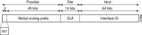
Global IPv6 addresses are defined by a global routing prefix, a subnet ID, and an interface ID. Figure 46-1 shows the structure of a global address.
Figure 46-1 Global Address Format
Addresses with a prefix of 2000::/3 (001) through E000::/3 (111) are required to have 64-bit interface identifiers in the extended universal identifier (EUI)-64 format. The Internet Assigned Numbers Authority (IANA) allocates the IPv6 address space in the range of 2000::/16 to regional registries.
The aggregatable global address typically consists of a 48-bit global routing prefix and a 16-bit subnet ID or Site-Level Aggregator (SLA). In the IPv6 aggregatable global unicast address format document (RFC 2374), the global routing prefix included two other hierarchically structured fields named Top-Level Aggregator (TLA) and Next-Level Aggregator (NLA).The IETF decided to remove the TLS and NLA fields from the RFCs because these fields are policy-based. Some existing IPv6 networks deployed before the change might still be using networks based on the older architecture.
A 16-bit subnet field called the subnet ID could be used by individual organizations to create their own local addressing hierarchy and to identify subnets. A subnet ID is similar to a subnet in IPv4, except that an organization with an IPv6 subnet ID can support up to 65,535 individual subnets.
An interface ID is used to identify interfaces on a link. The interface ID must be unique to the link. They may also be unique over a broader scope. In many cases, an interface ID will be the same as, or based on, the link-layer address of an interface, which results in a globally unique interface ID. Interface IDs used in aggregatable global unicast and other IPv6 address types must be 64 bits long and constructed in the modified EUI-64 format.
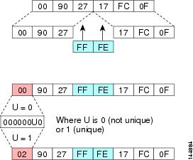
Cisco MDS SAN-OS supports IEEE 802 interface types (for example, Gigabit Ethernet interfaces). The first three octets (24 bits) are taken from the Organizationally Unique Identifier (OUI) of the 48-bit link-layer address (MAC address) of the interface, the fourth and fifth octets (16 bits) are a fixed hexadecimal value of FFFE, and the last three octets (24 bits) are taken from the last three octets of the MAC address. The construction of the interface ID is completed by setting the Universal/Local (U/L) bit—the seventh bit of the first octet—to a value of 0 or 1. A value of 0 indicates a locally administered identifier; a value of 1 indicates a globally unique IPv6 interface identifier (see Figure 46-2).
Figure 46-2 Interface Identifier Format
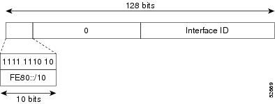
Link-Local Address
A link-local address is an IPv6 unicast address that is automatically configured on an interface using the link-local prefix FE80::/10 and the interface identifier in the modified EUI-64 format. Link-local addresses are used in the neighbor discovery protocol and the stateless autoconfiguration process. Nodes on a local link can use link-local addresses to communicate. Figure 46-3 shows the structure of a link-local address.
Figure 46-3 Link-Local Address Format
IPv6 Address Type: Multicast
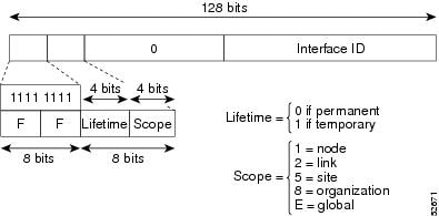
An IPv6 multicast address is an IPv6 address that has a prefix of FF00::/8 (1111 1111). An IPv6 multicast address is an identifier for a set of interfaces that typically belong to different nodes. A packet sent to a multicast address is delivered to all interfaces identified by the multicast address. The second octet following the prefix defines the lifetime and scope of the multicast address. A permanent multicast address has a lifetime parameter equal to 0; a temporary multicast address has a lifetime parameter equal to 1. A multicast address has the scope of a node, link, site, or organization, or a global scope has a scope parameter of 1, 2, 5, 8, or E, respectively. For example, a multicast address with the prefix FF02::/16 is a permanent multicast address with a link scope. Figure 46-4 shows the format of the IPv6 multicast address.
Figure 46-4 IPv6 Multicast Address Format
IPv6 hosts are required to join (receive packets destined for) the following multicast groups:
•
•
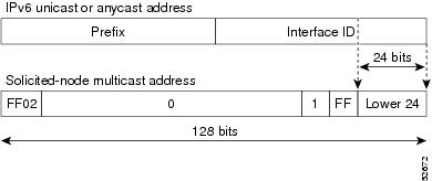
The solicited-node multicast address is a multicast group that corresponds to an IPv6 unicast address. IPv6 nodes must join the associated solicited-node multicast group for every unicast address to which it is assigned. The IPv6 solicited-node multicast address has the prefix FF02:0:0:0:0:1:FF00:0000/104 concatenated with the 24 low-order bits of a corresponding IPv6 unicast address. (See Figure 46-5.) For example, the solicited-node multicast address corresponding to the IPv6 address 2037::01:800:200E:8C6C is FF02::1:FF0E:8C6C. Solicited-node addresses are used in neighbor solicitation messages.
Figure 46-5 IPv6 Solicited-Node Multicast Address Format
Note
ICMP for IPv6
Internet Control Message Protocol (ICMP) in IPv6 functions the same as ICMP in IPv4—ICMP generates error messages such as ICMP destination unreachable messages, and informational messages such as ICMP echo request and reply messages. Additionally, ICMP packets in IPv6 are used in the IPv6 neighbor discovery process, path MTU discovery, and the Multicast Listener Discovery (MLD) protocol for IPv6. MLD is based on version 2 of the Internet Group Management Protocol (IGMP) for IPv4.
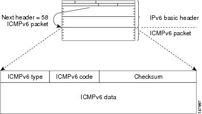
A value of 58 in the Next Header field of the basic IPv6 packet header identifies an IPv6 ICMP packet. ICMP packets in IPv6 resemble a transport-layer packet in the sense that the ICMP packet follows all the extension headers and is the last piece of information in the IPv6 packet. Within IPv6 ICMP packets, the ICMPv6 Type and ICMPv6 Code fields identify IPv6 ICMP packet specifics, such as the ICMP message type. The value in the Checksum field is derived (computed by the sender and checked by the receiver) from the fields in the IPv6 ICMP packet and the IPv6 pseudoheader. The ICMPv6 Data field contains error or diagnostic information relevant to IP packet processing. Figure 46-6 shows the IPv6 ICMP packet header format.
Figure 46-6 IPv6 ICMP Packet Header Format
Path MTU Discovery for IPv6
As in IPv4, path MTU discovery in IPv6 allows a host to dynamically discover and adjust to differences in the MTU size of every link along a given data path. In IPv6, however, fragmentation is handled by the source of a packet when the path MTU of one link along a given data path is not large enough to accommodate the size of the packets. Having IPv6 hosts handle packet fragmentation saves IPv6 router processing resources and helps IPv6 networks run more efficiently.
Note
In IPv6, the minimum link MTU is 1280 octets. We recommend using an maximum transmission unit (MTU) value of 1500 octets for IPv6 links.
IPv6 Neighbor Discovery
The IPv6 neighbor discovery process uses ICMP messages and solicited-node multicast addresses to determine the link-layer address of a neighbor on the same network (local link), verify the reachability of a neighbor, and keep track of neighboring routers.
IPv6 Neighbor Solicitation and Advertisement Messages
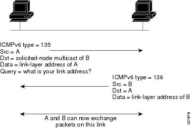
A value of 135 in the Type field of the ICMP packet header identifies a neighbor solicitation message. Neighbor solicitation messages are sent on the local link when a node wants to determine the link-layer address of another node on the same local link. (See Figure 46-7.) When a node wants to determine the link-layer address of another node, the source address in a neighbor solicitation message is the IPv6 address of the node sending the neighbor solicitation message. The destination address in the neighbor solicitation message is the solicited-node multicast address that corresponds to the IPv6 address of the destination node. The neighbor solicitation message also includes the link-layer address of the source node.
Figure 46-7 IPv6 Neighbor Discovery—Neighbor Solicitation Message
After receiving the neighbor solicitation message, the destination node replies by sending a neighbor advertisement message, which has a value of 136 in the Type field of the ICMP packet header, on the local link. The source address in the neighbor advertisement message is the IPv6 address of the node (more specifically, the IPv6 address of the node interface) sending the neighbor advertisement message. The destination address in the neighbor advertisement message is the IPv6 address of the node that sent the neighbor solicitation message. The data portion of the neighbor advertisement message includes the link-layer address of the node sending the neighbor advertisement message.
After the source node receives the neighbor advertisement, the source node and destination node can communicate.
Neighbor solicitation messages are also used to verify the reachability of a neighbor after the link-layer address of a neighbor is identified. When a node wants to verifying the reachability of a neighbor, the destination address in a neighbor solicitation message is the unicast address of the neighbor.
Neighbor advertisement messages are also sent when there is a change in the link-layer address of a node on a local link. When there is such a change, the destination address for the neighbor advertisement is the all-node multicast address.
Neighbor solicitation messages are also used to verify the reachability of a neighbor after the link-layer address of a neighbor is identified. Neighbor unreachability detection identifies the failure of a neighbor or the failure of the forward path to the neighbor, and is used for all paths between hosts and neighboring nodes (hosts or routers). Neighbor unreachability detection is performed for neighbors to which only unicast packets are being sent and is not performed for neighbors to which multicast packets are being sent.
A neighbor is considered reachable when the neighbor returns a positive acknowledgment indicating that it has received and processed packets previously sent to it. A positive acknowledgment could be from an upper-layer protocol such as TCP indicating that a connection is making forward progress (reaching its destination) or the receipt of a neighbor advertisement message in response to a neighbor solicitation message. If packets are reaching the peer, they are also reaching the next-hop neighbor of the source. Therefore, forward progress is also a confirmation that the next-hop neighbor is reachable.
For destinations that are not on the local link, forward progress implies that the first-hop router is reachable. When acknowledgments from an upper-layer protocol are not available, a node probes the neighbor using unicast neighbor solicitation messages to verify that the forward path is still working. The return of a solicited neighbor advertisement message from the neighbor is a positive acknowledgment that the forward path is still working (neighbor advertisement messages that have the solicited flag set to a value of 1 are sent only in response to a neighbor solicitation message). Unsolicited messages confirm only the one-way path from the source to the destination node; solicited neighbor advertisement messages indicate that a path is working in both directions.
Note
Neighbor solicitation messages are also used in the stateless autoconfiguration process to verify the uniqueness of unicast IPv6 addresses before the addresses are assigned to an interface. Duplicate address detection is performed first on a new, link-local IPv6 address before the address is assigned to an interface (the new address remains in a tentative state while duplicate address detection is performed). Specifically, a node sends a neighbor solicitation message with an unspecified source address and a tentative link-local address in the body of the message. If another node is already using that address, the node returns a neighbor advertisement message that contains the tentative link-local address. If another node is simultaneously verifying the uniqueness of the same address, that node also returns a neighbor solicitation message. If no neighbor advertisement messages are received in response to the neighbor solicitation message and no neighbor solicitation messages are received from other nodes that are attempting to verify the same tentative address, the node that sent the original neighbor solicitation message considers the tentative link-local address to be unique and assigns the address to the interface.
Every IPv6 unicast address (global or link-local) must be checked for uniqueness on the link; however, until the uniqueness of the link-local address is verified, duplicate address detection is not performed on any other IPv6 addresses associated with the link-local address.
Router Discovery
Router discovery performs both router solicitation and router advertisement. Router solicitations are sent by hosts to all-routers multicast addresses. Router advertisements are sent by routers in response to solicitations or unsolicited and contain default router information as well as additional parameters such as the MTU and hop limit.
IPv6 Stateless Autoconfiguration
All interfaces on IPv6 nodes must have a link-local address, which is automatically configured from the identifier for an interface and the link-local prefix FE80::/10. A link-local address enables a node to communicate with other nodes on the link and can be used to further configure the node.
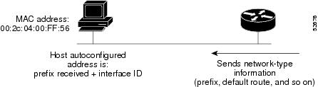
Nodes can connect to a network and automatically generate site-local and global IPv6 address without the need for manual configuration or help of a server, such as a DHCP server. With IPv6, a router on the link advertises in router advertisement (RA) messages any site-local and global prefixes, and its willingness to function as a default router for the link. RA messages are sent periodically and in response to router solicitation messages, which are sent by hosts at system startup. (See Figure 46-8.)
Figure 46-8 IPv6 Stateless Autoconfiguration
A node on the link can automatically configure site-local and global IPv6 addresses by appending its interface identifier (64 bits) to the prefixes (64 bits) included in the RA messages. The resulting 128-bit IPv6 addresses configured by the node are then subjected to duplicate address detection to ensure their uniqueness on the link. If the prefixes advertised in the RA messages are globally unique, then the IPv6 addresses configured by the node are also guaranteed to be globally unique. Router solicitation messages, which have a value of 133 in the Type field of the ICMP packet header, are sent by hosts at system startup so that the host can immediately autoconfigure without needing to wait for the next scheduled RA message.
Dual IPv4 and IPv6 Protocol Stacks
The dual IPv4 and IPv6 protocol stack technique is one technique for a transition to IPv6. It enables gradual, one-by-one upgrades to applications running on nodes. Applications running on nodes are upgraded to make use of the IPv6 protocol stack. Applications that are not upgraded—they support only the IPv4 protocol stack—can coexist with upgraded applications on the same node. New and upgraded applications simply make use of both the IPv4 and IPv6 protocol stacks. (See Figure 46-9.)
Figure 46-9 Dual IPv4 and IPv6 Protocol Stack Technique
A new API has been defined to support both IPv4 and IPv6 addresses and DNS requests. An application can be upgraded to the new API and still use only the IPv4 protocol stack. The Cisco MDS SAN-OS supports the dual IPv4 and IPv6 protocol stack technique. When an interface is configured with both an IPv4 and an IPv6 address, the interface will accept and process both IPv4 and IPv6 traffic.
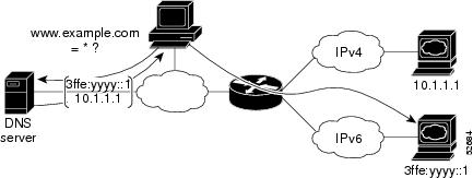
In Figure 46-10, an application that supports dual IPv4 and IPv6 protocol stacks requests all available addresses for the destination host name www.a.com from a DNS server. The DNS server replies with all available addresses (both IPv4 and IPv6 addresses) for www.a.com. The application chooses an address—in most cases, IPv6 addresses are the default choice—and connects the source node to the destination using the IPv6 protocol stack.
Figure 46-10 Dual IPv4 and IPv6 Protocol Stack Applications
Configuring Basic Connectivity for IPv6
The tasks in this section explain how to implement IPv6 basic connectivity. Each task in the list is identified as either required or optional. This section includes the following topics:
•
•
Configuring IPv6 Addressing and Enabling IPv6 Routing
This task explains how to assign IPv6 addresses to individual router interfaces and enable the processing of IPv6 traffic. By default, IPv6 addresses are not configured and IPv6 processing is disabled.
You can configure IPv6 addresses on the following interface types:
•
•
•
•
Note
The IPv6 prefixmust be in the form documented in RFC 2373, where the address is specified in hexadecimal using 16-bit values between colons.
The IPv6 prefix lengthis a decimal value that indicates how many of the high-order contiguous bits of the address comprise the prefix (the network portion of the address). A slash mark must precede the decimal value.Configuring a global IPv6 address on an interface automatically configures a link-local address and activates IPv6 for that interface. Additionally, the configured interface automatically joins the following required multicast groups for that link:
•
•
Note
Note
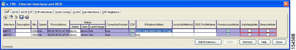
To configure an IPv6 address on an interface using Device Manager, follow these steps:
Step 1
You see the Gigabit Ethernet Configuration dialog box (see Figure 46-11).
Figure 46-11 Gigabit Ethernet Configuration in Device Manager
Step 2
You see the IP Address dialog box.
Step 3
Step 4
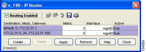
To enable IPv6 routing using Device Manager, follow these steps:
Step 1
Figure 46-12 IP Routing Configuration in Device Manager
Step 2
Step 3
Configuring IPv4 and IPv6 Protocol Addresses
When an interface in a Cisco networking device is configured with both an IPv4 and an IPv6 address, the interface can send and receive data on both IPv4 and IPv6 networks.
To configure an interface in a Cisco networking device to support both the IPv4 and IPv6 protocol stacks using Device Manager, follow these steps:
Step 1
You see the Gigabit Ethernet Configuration dialog box.
Step 2
You see the IP Address dialog box.
Step 3
Step 4
Configuring IPv6 Static Routes
Cisco MDS SAN-OS supports static routes for IPv6. This section includes the following topics:
•
Configuring a IPv6 Static Route
You must manually configure IPv6 static routes and define an explicit path between two networking devices. IPv6 static routes are not automatically updated and must be manually reconfigured if the network topology changes.
To configure a IPv6 static route using Device Manager, follow these steps:
Step 1
You see the IP Routing Configuration dialog box.
Step 2
You see the Create IP Route dialog box.
Step 3
Step 4
Step 5
Step 6
Step 7
Step 8
Gigabit Ethernet IPv6-ACL Guidelines
Tip
Follow these guidelines when configuring IPv6-ACLs for Gigabit Ethernet interfaces:
•
Note
•
•
–
–
–
See Chapter 33, "Configuring IPv4 and IPv6 Access Control Lists" for information on applying IPv6-ACLs to an interface.
Transitioning from IPv4 to IPv6
Cisco MDS SAN-OS does not support any transitioning mechanisms from IPv4 to IPv6. However, you can use the transitioning schemes in the Cisco router products for this purpose. For information on configuring Cisco routers to transition your network, refer to the Implementing Tunneling for IPv6 document in the Cisco IOS IPv6 Configuration Library.
Default Settings
Table 46-2 lists the default settings for IPv6 parameters.