
Contents
- Using MSDP to Interconnect Multiple PIM-SM Domains
- Finding Feature Information
- Prerequisites for Using MSDP to Interconnect Multiple PIM-SM Domains
- Information About Using MSDP to Interconnect Multiple PIM-SM Domains
- Benefits of Using MSDP to Interconnect Multiple PIM-SM Domains
- Use of MSDP to Interconnect Multiple PIM-SM Domains
- MSDP Message Types
- SA Messages
- SA Request Messages
- SA Response Messages
- Keepalive Messages
- SA Message Origination Receipt and Processing
- SA Message Origination
- SA Message Receipt
- How RPF Check Rules Are Applied to SA Messages
- How the Software Determines the Rule to Apply to RPF Checks
- Rule 1 of RPF Checking of SA Messages in MSDP
- Implications of Rule 1 of RPF Checking on MSDP
- Rule 2 of RPF Checking of SA Messages in MSDP
- Implications of Rule 2 of RPF Checking on MSDP
- Rule 3 of RPF Checking of SA Messages in MSDP
- SA Message Processing
- MSDP Peers
- MSDP MD5 Password Authentication
- How MSDP MD5 Password Authentication Works
- Benefits of MSDP MD5 Password Authentication
- SA Message Limits
- MSDP Keepalive and Hold-Time Intervals
- MSDP Connection-Retry Interval
- Default MSDP Peers
- MSDP Mesh Groups
- Benefits of MSDP Mesh Groups
- SA Origination Filters
- Use of Outgoing Filter Lists in MSDP
- Use of Incoming Filter Lists in MSDP
- TTL Thresholds in MSDP
- SA Request Messages
- SA Request Filters
- How to Use MSDP to Interconnect Multiple PIM-SM Domains
- Configuring an MSDP Peer
- Shutting Down an MSDP Peer
- Configuring MSDP MD5 Password Authentication Between MSDP Peers
- Troubleshooting Tips
- Preventing DoS Attacks by Limiting the Number of SA Messages Allowed in the SA Cache from Specified MSDP Peers
- Adjusting the MSDP Keepalive and Hold-Time Intervals
- Adjusting the MSDP Connection-Retry Interval
- Configuring a Default MSDP Peer
- Configuring an MSDP Mesh Group
- Controlling SA Messages Originated by an RP for Local Sources
- Controlling the Forwarding of SA Messages to MSDP Peers Using Outgoing Filter Lists
- Controlling the Receipt of SA Messages from MSDP Peers Using Incoming Filter Lists
- Using TTL Thresholds to Limit the Multicast Data Sent in SA Messages
- Requesting Source Information from MSDP Peers
- Controlling the Response to Outgoing SA Request Messages from MSDP Peers Using SA Request Filters
- Including a Bordering PIM Dense Mode Region in MSDP
- Configuring an Originating Address Other Than the RP Address
- Monitoring MSDP
- Clearing MSDP Connections Statistics and SA Cache Entries
- Enabling SNMP Monitoring of MSDP
- Troubleshooting Tips
- Configuration Examples for Using MSDP to Interconnect Multiple PIM-SM Domains
- Example: Configuring an MSDP Peer
- Example: Configuring MSDP MD5 Password Authentication
- Example: Configuring a Default MSDP Peer
- Example: Configuring MSDP Mesh Groups
- Additional References
- Feature Information for Mullticast Source Discovery Protocol
Using MSDP to Interconnect Multiple PIM-SM Domains
This module describes the tasks associated with using Multicast Source Discovery Protocol (MSDP) to interconnect multiple Protocol Independent Multicast (PIM) Sparse Mode (SM) domains. The tasks explain how to configure MSDP peers, mesh groups, and default peers, how to use filters to control and scope MSDP activity, and how to monitor and maintain MSDP. Using MSDP with PIM-SM greatly reduces the complexity of connecting multiple PIM-SM domains.
- Finding Feature Information
- Prerequisites for Using MSDP to Interconnect Multiple PIM-SM Domains
- Information About Using MSDP to Interconnect Multiple PIM-SM Domains
- How to Use MSDP to Interconnect Multiple PIM-SM Domains
- Configuration Examples for Using MSDP to Interconnect Multiple PIM-SM Domains
- Additional References
- Feature Information for Mullticast Source Discovery Protocol
Finding Feature Information
Your software release may not support all the features documented in this module. For the latest feature information and caveats, see the release notes for your platform and software release. To find information about the features documented in this module, and to see a list of the releases in which each feature is supported, see the Feature Information Table at the end of this document.
Use Cisco Feature Navigator to find information about platform support and Cisco software image support. To access Cisco Feature Navigator, go to www.cisco.com/go/cfn. An account on Cisco.com is not required.
Prerequisites for Using MSDP to Interconnect Multiple PIM-SM Domains
Before you configure MSDP, the addresses of all MSDP peers must be known in Border Gateway Protocol (BGP).
Information About Using MSDP to Interconnect Multiple PIM-SM Domains
- Benefits of Using MSDP to Interconnect Multiple PIM-SM Domains
- Use of MSDP to Interconnect Multiple PIM-SM Domains
- MSDP Message Types
- SA Message Origination Receipt and Processing
- MSDP Peers
- MSDP MD5 Password Authentication
- SA Message Limits
- MSDP Keepalive and Hold-Time Intervals
- MSDP Connection-Retry Interval
- Default MSDP Peers
- MSDP Mesh Groups
- SA Origination Filters
- Use of Outgoing Filter Lists in MSDP
- Use of Incoming Filter Lists in MSDP
- TTL Thresholds in MSDP
- SA Request Messages
- SA Request Filters
Benefits of Using MSDP to Interconnect Multiple PIM-SM Domains
- Allows a rendezvous point (RP) to dynamically discover active sources outside of its domain.
- Introduces a more manageable approach for building multicast distribution trees between multiple domains.
Use of MSDP to Interconnect Multiple PIM-SM Domains
MSDP is a mechanism to connect multiple PIM-SM domains. The purpose of MSDP is to discover multicast sources in other PIM domains. The main advantage of MSDP is that it reduces the complexity of interconnecting multiple PIM-SM domains by allowing PIM-SM domains to use an interdomain source tree (rather than a common shared tree). When MSDP is configured in a network, RPs exchange source information with RPs in other domains. An RP can join the interdomain source tree for sources that are sending to groups for which it has receivers. The RP can do that because it is the root of the shared tree within its domain, which has branches to all points in the domain where there are active receivers. When a last-hop device learns of a new source outside the PIM-SM domain (through the arrival of a multicast packet from the source down the shared tree), it then can send a join toward the source and join the interdomain source tree.
 Note |
If the RP either has no shared tree for a particular group or a shared tree whose outgoing interface list is null, it does not send a join to the source in another domain. |
When MSDP is enabled, an RP in a PIM-SM domain maintains MSDP peering relationships with MSDP-enabled devices in other domains. This peering relationship occurs over a TCP connection, where primarily a list of sources sending to multicast groups is exchanged. MSDP uses TCP (port 639) for its peering connections. As with BGP, using point-to-point TCP peering means that each peer must be explicitly configured. The TCP connections between RPs, moreover, are achieved by the underlying routing system. The receiving RP uses the source lists to establish a source path. If the multicast sources are of interest to a domain that has receivers, multicast data is delivered over the normal, source-tree building mechanism provided by PIM-SM. MSDP is also used to announce sources sending to a group. These announcements must originate at the RP of the domain.
Note |
MSDP depends on BGP or multiprotocol BGP (MBGP) for interdomain operation. We recommended that you run MSDP on RPs sending to global multicast groups. |
The figure illustrates MSDP operating between two MSDP peers. PIM uses MSDP as the standard mechanism to register a source with the RP of a domain.
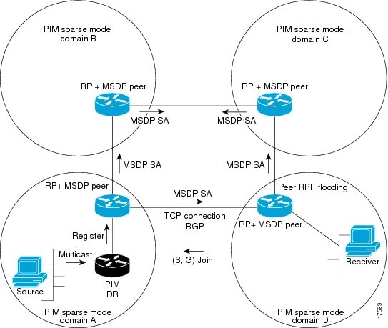
When MSDP is implemented, the following sequence of events occurs:
- When a PIM designated device (DR) registers a source with its RP as illustrated in the figure, the RP sends a Source-Active (SA) message to all of its MSDP peers.
Note |
The DR sends the encapsulated data to the RP only once per source (when the source goes active). If the source times out, this process happens again when it goes active again. This situation is different from the periodic SA message that contains all sources that are registered to the originating RP. Those SA messages are MSDP control packets, and, thus, do not contain encapsulated data from active sources. |
- The SA message identifies the source address, the group that the source is sending to, and the address or the originator ID of the RP, if configured.
- Each MSDP peer that receives the SA message floods the SA message to all of its peers downstream from the originator. In some cases (such as the case with the RPs in PIM-SM domains B and C in the figure), an RP may receive a copy of an SA message from more than one MSDP peer. To prevent looping, the RP consults the BGP next-hop database to determine the next hop toward the originator of the SA message. If both MBGP and unicast BGP are configured, MBGP is checked first, and then unicast BGP. That next-hop neighbor is the RPF-peer for the originator. SA messages that are received from the originator on any interface other than the interface to the RPF peer are dropped. The SA message flooding process, therefore, is referred to as peer-RPF flooding. Because of the peer-RPF flooding mechanism, BGP or MBGP must be running in conjunction with MSDP.
Note |
(M)BGP is not required in MSDP mesh group scenarios. For more information about MSDP mesh groups, see the Configuring an MSDP Mesh Group section. |
Note |
(M)BGP is not required in default MSDP peer scenarios or in scenarios where only one MSDP peer is configured. For more information, see the Configuring a Default MSDP Peer section. |
- When an RP receives an SA message, it checks to see whether there are any members of the advertised groups in its domain by checking to see whether there are interfaces on the group's (*, G) outgoing interface list. If there are no group members, the RP does nothing. If there are group members, the RP sends an (S, G) join toward the source. As a result, a branch of the interdomain source tree is constructed across autonomous system boundaries to the RP. As multicast packets arrive at the RP, they are then forwarded down its own shared tree to the group members in the RP's domain. The members' DRs then have the option of joining the rendezvous point tree (RPT) to the source using standard PIM-SM procedures.
- The originating RP continues to send periodic SA messages for the (S, G) state every 60 seconds for as long as the source is sending packets to the group. When an RP receives an SA message, it caches the SA message. Suppose, for example, that an RP receives an SA message for (172.16.5.4, 228.1.2.3) from originating RP 10.5.4.3. The RP consults its mroute table and finds that there are no active members for group 228.1.2.3, so it passes the SA message to its peers downstream of 10.5.4.3. If a host in the domain then sends a join to the RP for group 228.1.2.3, the RP adds the interface toward the host to the outgoing interface list of its (*, 224.1.2.3) entry. Because the RP caches SA messages, the device will have an entry for (172.16.5.4, 228.1.2.3) and can join the source tree as soon as a host requests a join.
Note |
In all current and supported software releases, caching of MSDP SA messages is mandatory and cannot be manually enabled or disabled. By default, when an MSDP peer is configured, the ip multicast cache-sa-state command will automatically be added to the running configuration. |
MSDP Message Types
There are four basic MSDP message types, each encoded in their own Type, Length, and Value (TLV) data format.
SA Messages
SA messages are used to advertise active sources in a domain. In addition, these SA messages may contain the initial multicast data packet that was sent by the source.
SA messages contain the IP address of the originating RP and one or more (S, G) pairs being advertised. In addition, the SA message may contain an encapsulated data packet.
Note |
For more information about SA messages, see the SA Message Origination Receipt and Processing section. |
SA Request Messages
SA request messages are used to request a list of active sources for a specific group. These messages are sent to an MSDP SA cache that maintains a list of active (S, G) pairs in its SA cache. Join latency can be reduced by using SA request messages to request the list of active sources for a group instead of having to wait up to 60 seconds for all active sources in the group to be readvertised by originating RPs.
Note |
For more information about SA request messages, see the Requesting Source Information from MSDP Peers section. |
SA Response Messages
SA response messages are sent by the MSDP peer in response to an SA request message. SA response messages contain the IP address of the originating RP and one or more (S, G) pairs of the active sources in the originating RP's domain that are stored in the cache.
Note |
For more information about SA response messages, see the Controlling the Response to Outgoing SA Request Messages from MSDP Peers Using SA Request Filters section. |
Keepalive Messages
Keepalive messages are sent every 60 seconds in order to keep the MSDP session active. If no keepalive messages or SA messages are received for 75 seconds, the MSDP session is reset.
Note |
For more information about keepalive messages, see the Adjusting the MSDP Keepalive and Hold-Time Intervals section. |
SA Message Origination Receipt and Processing
The section describes SA message origination, receipt, and processing in detail.
SA Message Origination
SA messages are triggered by an RP (assuming MSDP is configured) when any new source goes active within a local PIM-SM domain. A local source is a source that is directly connected to the RP or is the first-hop DR that has registered with it. An RP originates SA messages only for local sources in its PIM-SM domain; that is, for local sources that register with it.
Note |
A local source is denoted by the A flag being set in the (S, G) mroute entry on the RP (which can be viewed in the output of the show ip mroute command). This flag indicates that the source is a candidate for advertisement by the RP to other MSDP peers. |
When a source is in the local PIM-SM domain, it causes the creation of (S, G) state in the RP. New sources are detected by the RP either by the receipt of a register message or the arrival of the first (S, G) packet from a directly connected source. The initial multicast packet sent by the source (either encapsulated in the register message or received from a directly connected source) is encapsulated in the initial SA message.
SA Message Receipt
SA messages are only accepted from the MSDP RPF peer that is in the best path back toward the originator. The same SA message arriving from other MSDP peers must be ignored or SA loops can occur. Deterministically selecting the MSDP RPF peer for an arriving SA message requires knowledge of the MSDP topology. However, MSDP does not distribute topology information in the form of routing updates. MSDP infers this information by using (M)BGP routing data as the best approximation of the MSDP topology for the SA RPF check mechanism. An MSDP topology, therefore, must follow the same general topology as the BGP peer topology. Besides a few exceptions (such as default MSDP peers and MSDP peers in MSDP mesh groups), MSDP peers, in general should also be (M)BGP peers.
- How RPF Check Rules Are Applied to SA Messages
- How the Software Determines the Rule to Apply to RPF Checks
- Rule 1 of RPF Checking of SA Messages in MSDP
- Implications of Rule 1 of RPF Checking on MSDP
- Rule 2 of RPF Checking of SA Messages in MSDP
- Implications of Rule 2 of RPF Checking on MSDP
- Rule 3 of RPF Checking of SA Messages in MSDP
How RPF Check Rules Are Applied to SA Messages
The rules that apply to RPF checks for SA messages are dependent on the BGP peerings between the MSDP peers:
- Rule 1: Applied when the sending MSDP peer is also an interior (M)BGP peer.
- Rule 2: Applied when the sending MSDP peer is also an exterior (M)BGP peer.
- Rule 3: Applied when the sending MSDP peer is not an (M)BGP peer.
RPF checks are not performed in the following cases:
- If the sending MSDP peer is the only MSDP peer, which would be the case if only a single MSDP peer or a default MSDP peer is configured.
- If the sending MSDP peer is a member of a mesh group.
- If the sending MSDP peer address is the RP address contained in the SA message.
How the Software Determines the Rule to Apply to RPF Checks
The software uses the following logic to determine which RPF rule to apply to RPF checks:
The implication of the RPF check rule selection is as follows: The IP address used to configure an MSDP peer on a device must match the IP address used to configure the (M)BGP peer on the same device.
Rule 1 of RPF Checking of SA Messages in MSDP
Rule 1 of RPF checking in MSDP is applied when the sending MSDP peer is also an i(M)BGP peer. When Rule 1 is applied, the RPF check proceeds as follows:
- The peer searches the BGP Multicast Routing Information Base (MRIB) for the best path to the RP that originated the SA message. If a path is not found in the MRIB, the peer then searches the Unicast Routing Information Base (URIB). If a path is still not found, the RPF check fails.
- If the previous search succeeds (that is, the best path is found), the peer then determines the address of the BGP neighbor for this best path, which will be the address of the BGP neighbor that sent the peer the path in BGP update messages.
Note |
The BGP neighbor address is not the same as the next-hop address in the path. Because i(M)BGP peers do not update the next-hop attribute of a path, the next-hop address usually is not the same as the address of the BGP peer that sent us the path. |
Note |
The BGP neighbor address is not necessarily the same as the BGP ID of the peer that sent the peer the path. |
Implications of Rule 1 of RPF Checking on MSDP
The MSDP topology must mirror the (M)BGP topology. In general, wherever there is an i(M)BGP peer connection between two devices, an MSDP peer connection should be configured. More specifically, the IP address of the far-end MSDP peer connection must be the same as the far-end i(M)BGP peer connection. The addresses must be the same because the BGP topology between i(M)BGP peers inside an autonomous system is not described by the AS path. If it were always the case that i(M)BGP peers updated the next-hop address in the path when sending an update to another i(M)BGP peer, then the peer could rely on the next-hop address to describe the i(M)BGP topology (and hence the MSDP topology). However, because the default behavior for i(M)BGP peers is to not update the next-hop address, the peer cannot rely on the next-hop address to describe the (M)BGP topology (MSDP topology). Instead, the i(M)BGP peer uses the address of the i(M)BGP peer that sent the path to describe the i(M)BGP topology (MSDP topology) inside the autonomous system.
 Tip |
Care should be taken when configuring the MSDP peer addresses to make sure that the same address is used for both i(M)BGP and MSDP peer addresses. |
Rule 2 of RPF Checking of SA Messages in MSDP
Rule 2 of RPF checking in MSDP is applied when the sending MSDP peer is also an e(M)BGP peer. When Rule 2 is applied, the RPF check proceeds as follows:
- The peer searches the BGP MRIB for the best path to the RP that originated the SA message. If a path is not found in the MRIB, the peer then searches the URIB. If a path is still not found, the RPF check fails.
- If the previous search succeeds (that is, the best path is found), the peer then examines the path. If the first autonomous system in the best path to the RP is the same as the autonomous system of the e(M)BGP peer (which is also the sending MSDP peer), then the RPF check succeeds; otherwise it fails.
Implications of Rule 2 of RPF Checking on MSDP
The MSDP topology must mirror the (M)BGP topology. In general, wherever there is an e(M)BGP peer connection between two devices, an MSDP peer connection should be configured. As opposed to Rule 1, the IP address of the far-end MSDP peer connection does not have to be the same as the far-end e(M)BGP peer connection.The reason that the addresses do not have to be identical is that BGP topology between two e(M)BGP peers is not described by the AS path.
Rule 3 of RPF Checking of SA Messages in MSDP
Rule 3 of RPF checking is applied when the sending MSDP peer is not a (M)BGP peer at all. When Rule 3 is applied, the RPF check proceeds as follows:
- The peer searches the BGP MRIB for the best path to the RP that originated the SA message. If a path is not found in the MRIB, the peer then searches the URIB. If a path is still not found, the RPF check fails.
- If the previous search succeeds (that is, the best path to the RP that originated the SA message is found), the peer then searches the BGP MRIB for the best path to the MSDP peer that sent the SA message. If a path is not found in the MRIB, the peer then searches the URIB. If a path is still not found, the RPF check fails.
Note |
The autonomous system of the MSDP peer that sent the SA is the origin autonomous system, which is the last autonomous system in the AS path to the MSDP peer. |
- If the first autonomous system in the best path to the RP is the same as the autonomous system of the sending MSDP peer, then the RPF check succeeds; otherwise it fails.
SA Message Processing
The following steps are taken by an MSDP peer whenever it processes an SA message:
- Using the group address G of the (S, G) pair in the SA message, the peer locates the associated (*, G) entry in the mroute table. If the (*, G) entry is found and its outgoing interface list is not null, then there are active receivers in the PIM-SM domain for the source advertised in the SA message.
- The MSDP peer then creates an (S, G) entry for the advertised source.
- If the (S, G) entry did not already exist, the MSDP peer immediately triggers an (S, G) join toward the source in order to join the source tree.
- The peer then floods the SA message to all other MSDP peers with the exception of:
Note |
SA messages are stored locally in the device's SA cache. |
MSDP Peers
Like BGP, MSDP establishes neighbor relationships with other MSDP peers. MSDP peers connect using TCP port 639. The lower IP address peer takes the active role of opening the TCP connection. The higher IP address peer waits in LISTEN state for the other to make the connection. MSDP peers send keepalive messages every 60 seconds. The arrival of data performs the same function as the keepalive message and keeps the session from timing out. If no keepalive messages or data is received for 75 seconds, the TCP connection is reset.
MSDP MD5 Password Authentication
The MSDP MD5 password authentication feature is an enhancement to support Message Digest 5 (MD5) signature protection on a TCP connection between two MSDP peers. This feature provides added security by protecting MSDP against the threat of spoofed TCP segments being introduced into the TCP connection stream.
How MSDP MD5 Password Authentication Works
Developed in accordance with RFC 2385, the MSDP MD5 password authentication feature is used to verify each segment sent on the TCP connection between MSDP peers. The ip msdp password peer command is used to enable MD5 authentication for TCP connections between two MSDP peers. When MD5 authentication is enabled between two MSDP peers, each segment sent on the TCP connection between the peers is verified. MD5 authentication must be configured with the same password on both MSDP peers; otherwise, the connection between them will not be made. Configuring MD5 authentication causes the Cisco IOS software to generate and verify the MD5 digest of every segment sent on the TCP connection.
SA Message Limits
The ip msdp sa-limit command is used to limit the overall number of SA messages that a device can accept from specified MSDP peers. When the ip msdp sa-limit command is configured, the device maintains a per-peer count of SA messages stored in the SA cache and will ignore new messages from a peer if the configured SA message limit for that peer has been reached.
The ip msdp sa-limit command was introduced as a means to protect an MSDP-enabled device from denial of service (DoS) attacks. We recommended that you configure SA message limits for all MSDP peerings on the device. An appropriately low SA limit should be configured on peerings with a stub MSDP region (for example, a peer that may have some further downstream peers but that will not act as a transit for SA messages across the rest of the Internet). A high SA limit should be configured for all MSDP peerings that act as transits for SA messages across the Internet.
MSDP Keepalive and Hold-Time Intervals
The ip msdp keepalive command is used to adjust the interval at which an MSDP peer will send keepalive messages and the interval at which the MSDP peer will wait for keepalive messages from other peers before declaring them down.
Once an MSDP peering session is established, each side of the connection sends a keepalive message and sets a keepalive timer. If the keepalive timer expires, the local MSDP peer sends a keepalive message and restarts its keepalive timer; this interval is referred to as the keepalive interval. The keepalive-intervalargument is used to adjust the interval for which keepalive messages will be sent. The keepalive timer is set to the value specified for the keepalive-intervalargument when the peer comes up. The keepalive timer is reset to the value of the keepalive-interval argument whenever an MSDP keepalive message is sent to the peer and reset when the timer expires. The keepalive timer is deleted when an MSDP peering session is closed. By default, the keepalive timer is set to 60 seconds.
Note |
The value specified for the keepalive-interval argument must be less than the value specified for the holdtime-intervalargument and must be at least one second. |
The hold-time timer is initialized to the value of the hold-time-interval argument whenever an MSDP peering connection is established, and is reset to the value of the hold-time-intervalargument whenever an MSDP keepalive message is received. The hold-time timer is deleted whenever an MSDP peering connection is closed. By default, the hold-time interval is set to 75 seconds.
Use the hold-time-interval argument to adjust the interval at which the MSDP peer will wait for keepalive messages from other peers before declaring them down.
MSDP Connection-Retry Interval
You can adjust the interval at which all MSDP peers will wait after peering sessions are reset before attempting to reestablish the peering sessions. This interval is referred to as the connection-retry interval. By default, MSDP peers will wait 30 seconds after the session is reset before attempting to reestablish sessions with other peers. The modified configured connection-retry interval applies to all MSDP peering sessions on the device.
Default MSDP Peers
In most scenarios, an MSDP peer is also a BGP peer. If an autonomous system is a stub or nontransit autonomous system, and particularly if the autonomous system is not multihomed, there is little or no reason to run BGP to its transit autonomous system. A static default route at the stub autonomous system, and a static route pointing to the stub prefixes at the transit autonomous system, is generally sufficient. But if the stub autonomous system is also a multicast domain and its RP must peer with an RP in the neighboring domain, MSDP depends on the BGP next-hop database for its peer-RPF checks. You can disable this dependency on BGP by defining a default peer from which to accept all SA messages without performing the peer-RPF check. A default MSDP peer must be a previously configured MSDP peer.
A stub autonomous system also might want to have MSDP peerings with more than one RP for the sake of redundancy. For example, SA messages cannot just be accepted from multiple default peers, because there is no RPF check mechanism. Instead, SA messages are accepted from only one peer. If that peer fails, SA messages are then accepted from the other peer. The underlying assumption here, of course, is that both default peers are sending the same SA messages.
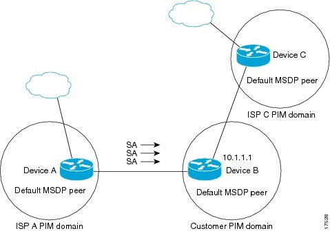
The figure illustrates a scenario where default MSDP peers might be used. In the figure, a customer that owns Device B is connected to the Internet through two Internet service providers (ISPs), one that owns Device A and the other that owns Device C. They are not running BGP or MBGP between them. In order for the customer to learn about sources in the ISP domain or in other domains, Device B identifies Device A as its default MSDP peer. Device B advertises SA messages to both Device A and Device C, but accepts SA messages either from Device A only or Device C only. If Device A is the first default peer in the configuration, it will be used if it is up and running. Only if Device A is not running will Device B accept SA messages from Device C.
The ISP will also likely use a prefix list to define which prefixes it will accept from the customer device. The customer will define multiple default peers, each having one or more prefixes associated with it.
The customer has two ISPs to use. The customer defines both ISPs as default peers. As long as the first default peer identified in the configuration is up and running, it will be the default peer and the customer will accept all SA messages it receives from that peer.
Device B advertises SAs to Device A and Device C, but uses only Device A or Device C to accept SA messages. If Device A is first in the configuration, it will be used if it is up and running. Only when Device A is not running will Device B accept SAs from Device C. This is the behavior without a prefix list.
If you specify a prefix list, the peer will be a default peer only for the prefixes in the list. You can have multiple active default peers when you have a prefix list associated with each. When you do not have any prefix lists, you can configure multiple default peers, but only the first one is the active default peer as long as the device has connectivity to this peer and the peer is alive. If the first configured peer goes down or the connectivity to this peer goes down, the second configured peer becomes the active default, and so on.
MSDP Mesh Groups
An MSDP mesh group is a group of MSDP speakers that have fully meshed MSDP connectivity between one another. In other words, each of the MSDP peers in the group must have an MSDP peering relationship (MSDP connection) to every other MSDP peer in the group. When an MSDP mesh group is configured between a group of MSDP peers, SA message flooding is reduced. Because when an MSDP peer in the group receives an SA message from another MSDP peer in the group, it assumes that this SA message was sent to all the other MSDP peers in the group. As a result, it is not necessary for the receiving MSDP peer to flood the SA message to the other MSDP peers in the group.
Benefits of MSDP Mesh Groups
- Optimizes SA flooding--MSDP mesh groups are particularly useful for optimizing SA flooding when two or more peers are in a group.
- Reduces the amount of SA traffic across the Internet--When MSDP mesh groups are used, SA messages are not flooded to other mesh group peers.
- Eliminates RPF checks on arriving SA messages--When an MSDP mesh group is configured, SA messages are always accepted from mesh group peers.
SA Origination Filters
By default, an RP that is configured to run MSDP will originate SA messages for all local sources for which it is the RP. Local sources that register with an RP, therefore, will be advertised in SA messages, which in some cases is not desirable. For example, if sources inside a PIM-SM domain are using private addresses (for example, network 10.0.0.0/8), you should configure an SA origination filter to restrict those addresses from being advertised to other MSDP peers across the Internet.
To control what sources are advertised in SA messages, you can configure SA origination filters on an RP. By creating SA origination filters, you can control the sources advertised in SA messages as follows:
- You can configure an RP to prevent the device from advertising local sources in SA messages. The device will still forward SA messages from other MSDP peers in the normal fashion; it will just not originate any SA messages for local sources.
- You can configure the device to only originate SA messages for local sources sending to specific groups that match (S, G) pairs defined in the extended access list. All other local sources will not be advertised in SA messages.
- You can configure the device to only originate SA messages for local sources sending to specific groups that the match AS paths defined in an AS-path access list. All other local sources will not be advertised in SA messages.
- You can configure the device to only originate SA messages for local sources that match the criteria defined in the route map. All other local sources will not be advertised in SA messages.
- You configure an SA origination filter that includes an extended access list, an AS-path access list, and route map, or a combination thereof. In this case, all conditions must be true before any local sources are advertised in SA messages.
Use of Outgoing Filter Lists in MSDP
By default, an MSDP-enabled device forwards all SA messages it receives to all of its MSDP peers. However, you can prevent SA messages from being forwarded to MSDP peers by creating outgoing filter lists. Outgoing filter lists apply to all SA messages, whether locally originated or received from another MSDP peer, whereas SA origination filters apply only to locally originated SA messages. For more information about enabling a filter for MSDP SA messages originated by the local device, see the Controlling SA Messages Originated by an RP for Local Sources section.
By creating an outgoing filter list, you can control the SA messages that a device forwards to a peer as follows:
- You can filter all outgoing SA messages forwarded to a specified MSDP peer by configuring the device to stop forwarding its SA messages to the MSDP peer.
- You can filter a subset of outgoing SA messages forwarded to a specified MSDP peer based on (S, G) pairs defined in an extended access list by configuring the device to only forward SA messages to the MSDP peer that match the (S, G) pairs permitted in an extended access list. The forwarding of all other SA messages to the MSDP peer will be stopped.
- You can filter a subset of outgoing SA messages forwarded to a specified MSDP peer based on match criteria defined in a route map by configuring the device to only forward SA messages that match the criteria defined in the route map. The forwarding of all other SA messages to the MSDP peer will be stopped.
- You can filter a subset of outgoing SA messages from a specified peer based on the announcing RP address contained in the SA message by configuring the device to filter outgoing SA messages based on their origin, even after an SA message has been transmitted across one or more MSDP peers. The forwarding of all other SA messages to the MSDP peer will be stopped.
- You can configure an outgoing filter list that includes an extended access list, a route map, and either an RP access list or an RP route map. In this case, all conditions must be true for the MSDP peer to forward the outgoing SA message.
 Caution |
Arbitrary filtering of SA messages can result in downstream MSDP peers being starved of SA messages for legitimate active sources. Care, therefore, should be taken when using these sorts of filters. Normally, outgoing filter lists are used only to reject undesirable sources, such as sources using private addresses. |
Use of Incoming Filter Lists in MSDP
By default, an MSDP-enabled device receives all SA messages sent to it from its MSDP peers. However, you can control the source information that a device receives from its MSDP peers by creating incoming filter lists.
By creating incoming filter lists, you can control the incoming SA messages that a device receives from its peers as follows:
- You can filter all incoming SA messages from a specified MSDP peer by configuring the device to ignore all SA messages sent to it from the specified MSDP peer.
- You can filter a subset of incoming SA messages from a specified peer based on (S, G) pairs defined in an extended access list by configuring the device to only receive SA messages from the MSDP peer that match the (S, G) pairs defined in the extended access list. All other incoming SA messages from the MSDP peer will be ignored.
- You can filter a subset of incoming SA request messages from a specified peer based on match criteria defined in a route map by configuring the device to only receive SA messages that match the criteria defined in the route map. All other incoming SA messages from the MSDP peer will be ignored.
- You can filter a subset of incoming SA messages from a specified peer based on both (S, G) pairs defined in an extended access list and on match criteria defined in a route map by configuring the device to only receive incoming SA messages that both match the (S, G) pairs defined in the extended access list and match the criteria defined in the route map. All other incoming SA messages from the MSDP peer will be ignored.
- You can filter a subset of incoming SA messages from a specified peer based on the announcing RP address contained in the SA message by configuring the device to filter incoming SA messages based on their origin, even after the SA message may have already been transmitted across one or more MSDP peers.
- You can configure an incoming filter list that includes an extended access list, a route map, and either an RP access list or an RP route map. In this case, all conditions must be true for the MSDP peer to receive the incoming SA message.
Caution |
Arbitrary filtering of SA messages can result in downstream MSDP peers being starved of SA messages for legitimate active sources. Care, therefore, should be taken when using these sorts of filters. Normally, incoming filter lists are used only to reject undesirable sources, such as sources using private addresses. |
TTL Thresholds in MSDP
The time-to-live (TTL) value provides a means to limit the number of hops a packet can take before being dropped. The ip multicast ttl-threshold command is used to specify a TTL for data-encapsulated SA messages sent to specified MSDP peers. By default, multicast data packets in SA messages are sent to an MSDP peer, provided the TTL value of the packet is greater than 0, which is standard TTL behavior.
In general, a TTL-threshold problem can be introduced by the encapsulation of a source's initial multicast packet in an SA message. Because the multicast packet is encapsulated inside of the unicast SA message (whose TTL is 255), its TTL is not decremented as the SA message travels to the MSDP peer. Furthermore, the total number of hops that the SA message traverses can be drastically different than a normal multicast packet because multicast and unicast traffic may follow completely different paths to the MSDP peer and hence the remote PIM-SM domain. As a result, encapsulated packets can end up violating TTL thresholds. The solution to this problem is to configure a TTL threshold that is associated with any multicast packet that is encapsulated in an SA message sent to a particular MSDP peer using the ip multicast ttl-threshold command. The ip msdp ttl-threshold command prevents any multicast packet whose TTL in the IP header is less than the TTL value specified for the ttl-valueargument from being encapsulated in SA messages sent to that peer.
SA Request Messages
You can configure a noncaching device to send SA request messages to one or more specified MSDP peers.
If an noncaching RP has an MSDP peer that is caching SAs, you can reduce the join latency for a noncaching peer by enabling the noncaching peer to send SA request messages. When a host requests a join to a particular group, the noncaching RP sends an SA request message to its caching peers. If a peer has cached source information for the group in question, it sends the information to the requesting RP with an SA response message. The requesting RP uses the information in the SA response but does not forward the message to any other peers. If a noncaching RP receives an SA request, it sends an error message back to the requestor.
Note |
In all current and supported software releases, caching of MSDP SA messages is mandatory and cannot be manually enabled or disabled. By default, when an MSDP peer is configured, the configured commands are automatically added to the running configuration. |
SA Request Filters
By default, a device honors all outgoing SA request messages from its MSDP peers; that is, it sends cached source information to requesting MSDP peers in SA response messages. You can control the outgoing SA request messages that a device will honor from specified peers by creating an SA request filter. An SA request filter controls the outgoing SA requests that the device will honor from MSDP peers as follows:
- You can filter all SA request messages from a specified peer by configuring the device to ignore all SA requests from the specified MSDP peer.
- You can filter a subset of SA request messages from a specified peer based on groups defined in a standard access list by configuring the device to honor only SA request messages from the MSDP peer that match the groups defined in a standard access list. SA request messages from the specified peer for other groups will be ignored.
How to Use MSDP to Interconnect Multiple PIM-SM Domains
The first task is required; all other tasks are optional.
- Configuring an MSDP Peer
- Shutting Down an MSDP Peer
- Configuring MSDP MD5 Password Authentication Between MSDP Peers
- Preventing DoS Attacks by Limiting the Number of SA Messages Allowed in the SA Cache from Specified MSDP Peers
- Adjusting the MSDP Keepalive and Hold-Time Intervals
- Adjusting the MSDP Connection-Retry Interval
- Configuring a Default MSDP Peer
- Configuring an MSDP Mesh Group
- Controlling SA Messages Originated by an RP for Local Sources
- Controlling the Forwarding of SA Messages to MSDP Peers Using Outgoing Filter Lists
- Controlling the Receipt of SA Messages from MSDP Peers Using Incoming Filter Lists
- Using TTL Thresholds to Limit the Multicast Data Sent in SA Messages
- Requesting Source Information from MSDP Peers
- Controlling the Response to Outgoing SA Request Messages from MSDP Peers Using SA Request Filters
- Including a Bordering PIM Dense Mode Region in MSDP
- Configuring an Originating Address Other Than the RP Address
- Monitoring MSDP
- Clearing MSDP Connections Statistics and SA Cache Entries
- Enabling SNMP Monitoring of MSDP
Configuring an MSDP Peer
- IP multicast routing must be enabled and PIM-SM must be configured.
- With the exception of a single MSDP peer, default MSDP peer, and MSDP mesh group scenarios, all MSDP peers must be configured to run BGP prior to being configured for MSDP.
DETAILED STEPS
| Command or Action | Purpose | |||
|---|---|---|---|---|
|
Step 1
|
enable
Example: Device> enable |
Enables privileged EXEC mode. |
||
|
Step 2
|
configure terminal
Example: Device# configure terminal |
Enters global configuration mode. |
||
|
Step 3
|
ip msdp peer {peer-name| peer-address} [connect-source type number] [remote-as as-number]
Example: Device(config)# ip msdp peer 192.168.1.2 connect-source loopback0 |
Enables MSDP and configures an MSDP peer as specified by the DNS name or IP address.
|
||
|
Step 4
|
ip msdp description {peer-name| peer-address} text
Example: Device(config)# ip msdp description 192.168.1.2 router at customer a |
(Optional) Configures a description for a specified peer to make it easier to identify in a configuration or in show command output. |
||
|
Step 5
|
end
Example: Device(config)# end |
Exits global configuration mode and returns to privileged EXEC mode. |
Shutting Down an MSDP Peer
Perform this optional task to shut down an MSDP peer.
If you are configuring several MSDP peers and you do not want any of the peers to go active until you have finished configuring all of them, you can shut down each peer, configure each peer, and later bring each peer up. You might also want to shut down an MSDP session without losing the configuration for that MSDP peer.
Note |
When an MSDP peer is shut down, the TCP connection is terminated and not restarted until the peer is brought back up using the no ip msdp shutdown command (for the specified peer). |
DETAILED STEPS
Configuring MSDP MD5 Password Authentication Between MSDP Peers
DETAILED STEPS
Troubleshooting Tips
If a device has a password configured for an MSDP peer but the MSDP peer does not, a message such as the following will appear on the console while the devices attempt to establish an MSDP session between them:
%TCP-6-BADAUTH: No MD5 digest from [peer's IP address]:11003 to [local router's
IP address]:179
Similarly, if the two devices have different passwords configured, a message such as the following will appear on the console:
%TCP-6-BADAUTH: Invalid MD5 digest from [peer's IP address]:11004 to [local router's
IP address]:179
The debug ip tcp transactions command is used to display information on significant TCP transactions such as state changes, retransmissions, and duplicate packets. In the context of monitoring or troubleshooting MSDP MD5 password authentication, use the debug ip tcp transactions command to verify that the MD5 password is enabled and that the keepalive message is received by the MSDP peer.
Preventing DoS Attacks by Limiting the Number of SA Messages Allowed in the SA Cache from Specified MSDP Peers
Perform this optional (but highly recommended) task to limit the overall number of SA messages that the device can accept from specified MSDP peers. Performing this task protects an MSDP-enabled device from distributed denial-of-service (DoS) attacks.
Note |
We recommend that you perform this task for all MSDP peerings on the device. |
DETAILED STEPS
| Command or Action | Purpose | |||
|---|---|---|---|---|
|
Step 1
|
enable
Example: Device> enable |
Enables privileged EXEC mode. |
||
|
Step 2
|
configure terminal
Example: Device# configure terminal |
Enters global configuration mode. |
||
|
Step 3
|
ip msdp sa-limit {peer-address | peer-name} sa-limit
Example: Device(config)# ip msdp sa-limit 192.168.10.1 100 |
Limits the number of SA messages allowed in the SA cache from the specified MSDP. |
||
|
Step 4
|
Repeat Step 3 to configure SA limits for additional MSDP peers.
|
-- |
||
|
Step 5
|
exit
Example: Device(config)# exit |
Exits global configuration mode and returns to privileged EXEC mode. |
||
|
Step 6
|
show ip msdp count [as-number]
Example: Device# show ip msdp count |
(Optional) Displays the number of sources and groups originated in MSDP SA messages and the number of SA messages from an MSDP peer in the SA cache. |
||
|
Step 7
|
show ip msdp peer [peer-address | peer-name]
Example: Device# show ip msdp peer |
(Optional) Displays detailed information about MSDP peers.
|
||
|
Step 8
|
show ip msdp summary
Example: Device# show ip msdp summary |
(Optional) Displays MSDP peer status.
|
Adjusting the MSDP Keepalive and Hold-Time Intervals
Perform this optional task to adjust the interval at which an MSDP peer will send keepalive messages and the interval at which the MSDP peer will wait for keepalive messages from other peers before declaring them down. By default, it may take as long as 75 seconds for an MSDP peer to detect that a peering session with another MSDP peer has gone down. In network environments with redundant MSDP peers, decreasing the hold-time interval can expedite the reconvergence time of MSDP peers in the event that an MSDP peer fails.
Note |
We recommend that you do not change the command defaults for the ip msdp keepalive command, because the command defaults are in accordance with RFC 3618, Multicast Source Discovery Protocol. If your network environment requires that you modify the defaults, you must configure the same time values for the keepalive-interval and hold-time-interval arguments on both ends of the MSDP peering session. |
DETAILED STEPS
| Command or Action | Purpose | |
|---|---|---|
|
Step 1
|
enable
Example: Device> enable |
Enables privileged EXEC mode. |
|
Step 2
|
configure terminal
Example: Device# configure terminal |
Enters global configuration mode. |
|
Step 3
|
ip msdp keepalive {peer-address | peer-name} keepalive-interval hold-time-interval
Example: Device(config)# ip msdp keepalive 10.1.1.3 40 55 |
Configures the interval at which an MSDP peer will send keepalive messages and the interval at which the MSDP peer will wait for keepalive messages from other peers before declaring them down. |
|
Step 4
|
Repeat Step 3 to adjust the keepalive message interval for additional MSDP peers.
|
-- |
|
Step 5
|
exit
Example: Device(config)# exit |
Exits global configuration mode and returns to privileged EXEC mode. |
Adjusting the MSDP Connection-Retry Interval
Perform this optional task to adjust the interval at which MSDP peers will wait after peering sessions are reset before attempting to reestablish the peering sessions. In network environments where fast recovery of SA messages is required, such as in trading floor network environments, you may want to decrease the connection-retry interval to a time value less than the default value of 30 seconds.
DETAILED STEPS
| Command or Action | Purpose | |
|---|---|---|
|
Step 1
|
enable
Example: Device> enable |
Enables privileged EXEC mode. |
|
Step 2
|
configure terminal
Example: Device# configure terminal |
Enters global configuration mode. |
|
Step 3
|
ip msdp timer connection-retry-interval
Example: Device# ip msdp timer 45 |
Configures the interval at which MSDP peers will wait after peering sessions are reset before attempting to reestablish the peering sessions. |
|
Step 4
|
exit
Example: Device(config)# exit |
Exits global configuration mode and returns to privileged EXEC mode. |
Configuring a Default MSDP Peer
An MSDP default peer must be a previously configured MSDP peer. Before configuring a default MSDP peer, you must first configure an MSDP peer.
DETAILED STEPS
| Command or Action | Purpose | |
|---|---|---|
|
Step 1
|
enable
Example: Device> enable |
Enables privileged EXEC mode. |
|
Step 2
|
configure terminal
Example: Device# configure terminal |
Enters global configuration mode. |
|
Step 3
|
ip msdp default-peer {peer-address | peer-name} [prefix-list list]
Example: Device(config)# ip msdp default-peer 192.168.1.3 |
Configures a default peer from which to accept all MSDP SA messages |
|
Step 4
|
exit
Example: Device(config)# exit |
Exits global configuration mode and returns to privileged EXEC mode. |
Configuring an MSDP Mesh Group
Perform this optional task to configure an MSDP mesh group.
Note |
You can configure multiple mesh groups per device. |
DETAILED STEPS
| Command or Action | Purpose | |||
|---|---|---|---|---|
|
Step 1
|
enable
Example: Device> enable |
Enables privileged EXEC mode. |
||
|
Step 2
|
configure terminal
Example: Device# configure terminal |
Enters global configuration mode. |
||
|
Step 3
|
ip msdp mesh-group mesh-name {peer-address | peer-name}
Example: Device(config)# ip msdp mesh-group peermesh |
Configures an MSDP mesh group and indicates that an MSDP peer belongs to that mesh group.
|
||
|
Step 4
|
Repeat Step 3 to add MSDP peers as members of the mesh group.
|
-- |
||
|
Step 5
|
exit
Example: Device(config)# exit |
Exits global configuration mode and returns to privileged EXEC mode. |
Controlling SA Messages Originated by an RP for Local Sources
Perform this task to control SA messages originated by an RP by enabling a filter to restrict which registered sources are advertised in SA messages.
Note |
For best practice information related to configuring MSDP SA message filters, see the Multicast Source Discovery Protocol SA Filter Recommendations tech note. |
DETAILED STEPS
| Command or Action | Purpose | |||
|---|---|---|---|---|
|
Step 1
|
enable
Example: Device> enable |
Enables privileged EXEC mode. |
||
|
Step 2
|
configure terminal
Example: Device# configure terminal |
Enters global configuration mode. |
||
|
Step 3
|
ip msdp redistribute [list access-list] [asn as-access-list] [route-map map-name]
Example: Device(config)# ip msdp redistribute route-map customer-sources |
Enables a filter for MSDP SA messages originated by the local device.
|
||
|
Step 4
|
exit
Example: Device(config)# exit |
Exits global configuration mode and returns to privileged EXEC mode. |
Controlling the Forwarding of SA Messages to MSDP Peers Using Outgoing Filter Lists
Perform this optional task to control the forwarding of SA messages to MSDP peers by configuring outgoing filter lists.
Note |
For best practice information related to configuring MSDP SA message filters, see the Multicast Source Discovery Protocol SA Filter Recommendations tech note. |
DETAILED STEPS
| Command or Action | Purpose | |
|---|---|---|
|
Step 1
|
enable
Example: Device> enable |
Enables privileged EXEC mode. |
|
Step 2
|
configure terminal
Example: Device# configure terminal |
Enters global configuration mode. |
|
Step 3
|
ip msdp sa-filter out {peer-address | peer-name} [list access-list] [route-map map-name] [rp-list access-list | rp-route-map map-name]
Example: Device(config)# ip msdp sa-filter out 192.168.1.5 peerone |
Enables a filter for outgoing MSDP messages. |
|
Step 4
|
Repeat Step 3 to configure outgoing filter lists for additional MSDP peers.
|
-- |
|
Step 5
|
exit
Example: Device(config)# exit |
Exits global configuration mode and returns to privileged EXEC mode. |
Controlling the Receipt of SA Messages from MSDP Peers Using Incoming Filter Lists
Perform this optional task to control the receipt of incoming SA messages from MSDP peers.
Note |
For best practice information related to configuring MSDP SA message filters, see the Multicast Source Discovery Protocol SA Filter Recommendations tech note. |
DETAILED STEPS
| Command or Action | Purpose | |
|---|---|---|
|
Step 1
|
enable
Example: Device> enable |
Enables privileged EXEC mode. |
|
Step 2
|
configure terminal
Example: Device# configure terminal |
Enters global configuration mode. |
|
Step 3
|
ip msdp sa-filter in {peer-address | peer-name} [list access-list] [route-map map-name] [rp-list access-list | rp-route-map map-name]
Example: Device(config)# ip msdp sa-filter in 192.168.1.3 |
Enables a filter for incoming MSDP SA messages. |
|
Step 4
|
Repeat Step 3 to configure incoming filter lists for additional MSDP peers.
|
-- |
|
Step 5
|
exit
Example: Device(config)# exit |
Exits global configuration mode and returns to privileged EXEC mode. |
Using TTL Thresholds to Limit the Multicast Data Sent in SA Messages
Perform this optional task to establish a time to live (TTL) threshold to limit the multicast data sent in SA messages.
DETAILED STEPS
| Command or Action | Purpose | |
|---|---|---|
|
Step 1
|
enable
Example: Device> enable |
Enables privileged EXEC mode. |
|
Step 2
|
configure terminal
Example: Device# configure terminal |
Enters global configuration mode. |
|
Step 3
|
ip msdp ttl-threshold {peer-address | peer-name} ttl-value
Example:
Example: Device(config)# ip msdp ttl-threshold 192.168.1.5 8 |
Sets a TTL value for MSDP messages originated by the local device. |
|
Step 4
|
exit
Example: Device(config)# exit |
Exits global configuration mode and returns to privileged EXEC mode. |
Requesting Source Information from MSDP Peers
Perform this optional task to enable a device to request source information from MSDP peers.
Note |
Because SA caching is enabled by default and cannot be explicitly enabled or disabled in earlier Cisco software releases, performing this task is seldom needed. |
DETAILED STEPS
| Command or Action | Purpose | |
|---|---|---|
|
Step 1
|
enable
Example: Device> enable |
Enables privileged EXEC mode. |
|
Step 2
|
configure terminal
Example: Device# configure terminal |
Enters global configuration mode. |
|
Step 3
|
ip msdp sa-request {peer-address | peer-name}
Example: Device(config)# ip msdp sa-request 192.168.10.1 |
Specifies that the device send SA request messages to the specified MSDP peer. |
|
Step 4
|
Repeat Step 3 to specify that the device send SA request messages to additional MSDP caching peers.
|
-- |
|
Step 5
|
exit
Example: Device(config)# exit |
Exits global configuration mode and returns to privileged EXEC mode. |
Controlling the Response to Outgoing SA Request Messages from MSDP Peers Using SA Request Filters
Perform this optional task to control the outgoing SA request messages that the device will honor from MSDP peers.
DETAILED STEPS
| Command or Action | Purpose | |||
|---|---|---|---|---|
|
Step 1
|
enable
Example: Device> enable |
Enables privileged EXEC mode. |
||
|
Step 2
|
configure terminal
Example: Device# configure terminal |
Enters global configuration mode. |
||
|
Step 3
|
ip msdp filter-sa-request {peer-address | peer-name} [list access-list]
Example: Device(config)# ip msdp filter sa-request 172.31.2.2 list 1 |
Enables a filter for outgoing SA request messages.
|
||
|
Step 4
|
Repeat Step 3 to configure SA request filters for additional MSDP peers.
|
-- |
||
|
Step 5
|
exit
Example: Device(config)# exit |
Exits global configuration mode and returns to privileged EXEC mode. |
Including a Bordering PIM Dense Mode Region in MSDP
Perform this optional task to configure a border device to send SA messages for sources active in a PIM dense mode (PIM-DM) region.
You can have a device that borders a PIM-SM region and a PIM-DM region. By default, sources in the PIM-DM domain are not included in MSDP. You can configure this border device to send SA messages for sources active in the PIM-DM domain. If you do so, it is very important to also configure the ip msdp redistribute command to control what local sources from the PIM-DM domain are advertised. Not configuring this command can result in the (S, G) state remaining long after a source in the PIM-DM domain has stopped sending. For configuration information, see the Controlling SA Messages Originated by an RP for Local Sources section.
DETAILED STEPS
| Command or Action | Purpose | |
|---|---|---|
|
Step 1
|
enable
Example: Device> enable |
Enables privileged EXEC mode. |
|
Step 2
|
configure terminal
Example: Device# configure terminal |
Enters global configuration mode. |
|
Step 3
|
ip msdp border sa-address type number
Example: Device(config)# ip msdp border sa-address gigabitethernet0/0/0 |
Configures the device on the border between a PIM-SM and PIM-DM domain to originate SA messages for active sources in the PIM-DM domain. |
|
Step 4
|
exit
Example: Device(config)# exit |
Exits global configuration mode and returns to privileged EXEC mode. |
Configuring an Originating Address Other Than the RP Address
Perform this optional task to allow an MSDP speaker that originates an SA message to use the IP address of its interface as the RP address in the SA message.
- If you configure multiple devices in an MSDP mesh group for Anycast RP.
- If you have a device that borders a PIM-SM domain and a PIM-DM domain. If a device borders a PIM-SM domain and a PIM-DM domain and you want to advertise active sources within the PIM-DM domain, configure the RP address in SA messages to be the address of the originating device's interface.
MSDP is enabled and the MSDP peers are configured. For more information about configuring MSDP peers, see the Configuring an MSDP Peer section.
DETAILED STEPS
| Command or Action | Purpose | |
|---|---|---|
|
Step 1
|
enable
Example: Device> enable |
Enables privileged EXEC mode. |
|
Step 2
|
configure terminal
Example: Device# configure terminal |
Enters global configuration mode. |
|
Step 3
|
ip msdp originator-id type number
Example: Device(config)# ip msdp originator-id ethernet 1 |
Configures the RP address in SA messages to be the address of the originating device's interface. |
|
Step 4
|
exit
Example: Device(config)# exit |
Exits global configuration mode and returns to privileged EXEC mode. |
Monitoring MSDP
DETAILED STEPS
| Step 1 |
enable Example:
Device# enable
Enables privileged EXEC mode. |
| Step 2 |
debug ip msdp [peer-address | peer-name] [detail] [routes] Use this command to debug MSDP activity. Use the optional peer-address or peer-name argument to specify for which peer debug events are logged. The following is sample output from the debug ip msdp command: Example:
Device# debug ip msdp
MSDP debugging is on
Device#
MSDP: 224.150.44.254: Received 1388-byte message from peer
MSDP: 224.150.44.254: SA TLV, len: 1388, ec: 115, RP: 172.31.3.92
MSDP: 224.150.44.254: Peer RPF check passed for 172.31.3.92, used EMBGP peer
MSDP: 224.150.44.250: Forward 1388-byte SA to peer
MSDP: 224.150.44.254: Received 1028-byte message from peer
MSDP: 224.150.44.254: SA TLV, len: 1028, ec: 85, RP: 172.31.3.92
MSDP: 224.150.44.254: Peer RPF check passed for 172.31.3.92, used EMBGP peer
MSDP: 224.150.44.250: Forward 1028-byte SA to peer
MSDP: 224.150.44.254: Received 1388-byte message from peer
MSDP: 224.150.44.254: SA TLV, len: 1388, ec: 115, RP: 172.31.3.111
MSDP: 224.150.44.254: Peer RPF check passed for 172.31.3.111, used EMBGP peer
MSDP: 224.150.44.250: Forward 1388-byte SA to peer
MSDP: 224.150.44.250: Received 56-byte message from peer
MSDP: 224.150.44.250: SA TLV, len: 56, ec: 4, RP: 192.168.76.241
MSDP: 224.150.44.250: Peer RPF check passed for 192.168.76.241, used EMBGP peer
MSDP: 224.150.44.254: Forward 56-byte SA to peer
MSDP: 224.150.44.254: Received 116-byte message from peer
MSDP: 224.150.44.254: SA TLV, len: 116, ec: 9, RP: 172.31.3.111
MSDP: 224.150.44.254: Peer RPF check passed for 172.31.3.111, used EMBGP peer
MSDP: 224.150.44.250: Forward 116-byte SA to peer
MSDP: 224.150.44.254: Received 32-byte message from peer
MSDP: 224.150.44.254: SA TLV, len: 32, ec: 2, RP: 172.31.3.78
MSDP: 224.150.44.254: Peer RPF check passed for 172.31.3.78, used EMBGP peer
MSDP: 224.150.44.250: Forward 32-byte SA to peer
|
| Step 3 |
debug ip msdp resets Use this command to debug MSDP peer reset reasons. Example:
Device# debug ip msdp resets
|
| Step 4 |
show ip msdp count [as-number] Use this command to display the number of sources and groups originated in MSDP SA messages and the number of SA messages from an MSDP peer in the SA cache. The ip msdp cache-sa-state command must be configured for this command to produce any output. The following is sample output from the show ip msdp countcommand: Example:
Device# show ip msdp count
SA State per Peer Counters, <Peer>: <# SA learned>
    192.168.4.4: 8
SA State per ASN Counters, <asn>: <# sources>/<# groups>
    Total entries: 8
    ?: 8/8
|
| Step 5 |
show ip msdp peer [peer-address | peer-name] Use this command to display detailed information about MSDP peers. Use the optional peer-address or peer-name argument to display information about a particular peer. The following is sample output from the show ip msdp peercommand: Example:
Device# show ip msdp peer 192.168.4.4
MSDP Peer 192.168.4.4 (?), AS 64512 (configured AS)
  Connection status:
    State: Up, Resets: 0, Connection source: Loopback0 (2.2.2.2)
    Uptime(Downtime): 00:07:55, Messages sent/received: 8/18
    Output messages discarded: 0
    Connection and counters cleared 00:08:55 ago
  SA Filtering:
    Input (S,G) filter: none, route-map: none
    Input RP filter: none, route-map: none
    Output (S,G) filter: none, route-map: none
    Output RP filter: none, route-map: none
  SA-Requests:
    Input filter: none
  Peer ttl threshold: 0
  SAs learned from this peer: 8
  Input queue size: 0, Output queue size: 0
  MD5 signature protection on MSDP TCP connection: not enabled
|
| Step 6 |
show ip msdp sa-cache [group-address | source-address | group-name | source-name] [as-number] Use this command to display the (S, G) state learned from MSDP peers. The following is sample output from the show ip msdp sa-cachecommand: Example:
Device# show ip msdp sa-cache
MSDP Source-Active Cache - 8 entries
(10.44.44.5, 239.232.1.0), RP 192.168.4.4, BGP/AS 64512, 00:01:20/00:05:32, Peer 192.168.4.4
(10.44.44.5, 239.232.1.1), RP 192.168.4.4, BGP/AS 64512, 00:01:20/00:05:32, Peer 192.168.4.4
(10.44.44.5, 239.232.1.2), RP 192.168.4.4, BGP/AS 64512, 00:01:19/00:05:32, Peer 192.168.4.4
(10.44.44.5, 239.232.1.3), RP 192.168.4.4, BGP/AS 64512, 00:01:19/00:05:32, Peer 192.168.4.4
(10.44.44.5, 239.232.1.4), RP 192.168.4.4, BGP/AS 64512, 00:01:19/00:05:32, Peer 192.168.4.4
(10.44.44.5, 239.232.1.5), RP 192.168.4.4, BGP/AS 64512, 00:01:19/00:05:32, Peer 192.168.4.4
(10.44.44.5, 239.232.1.6), RP 192.168.4.4, BGP/AS 64512, 00:01:19/00:05:32, Peer 192.168.4.4
(10.44.44.5, 239.232.1.7), RP 192.168.4.4, BGP/AS 64512, 00:01:19/00:05:32, Peer 192.168.4.4
|
| Step 7 |
show ip msdp summary Use this command to display MSDP peer status. The following is sample output from the show ip msdp summary command: Example:
Device# show ip msdp summary
MSDP Peer Status Summary
Peer Address     AS    State    Uptime/  Reset SA    Peer Name
                                Downtime Count Count
192.168.4.4 4 Up 00:08:05 0 8 ? |
Clearing MSDP Connections Statistics and SA Cache Entries
DETAILED STEPS
| Command or Action | Purpose | |
|---|---|---|
|
Step 1
|
enable
Example: Device> enable |
Enables privileged EXEC mode. |
|
Step 2
|
clear ip msdp peer [peer-address | peer-name]
Example: Device# clear ip msdp peer |
Clears the TCP connection to the specified MSDP peer and resets all MSDP message counters. |
|
Step 3
|
clear ip msdp statistics [peer-address | peer-name]
Example: Device# clear ip msdp statistics |
Clears the statistics counters for the specified MSDP peer and resets all MSDP message counters. |
|
Step 4
|
clear ip msdp sa-cache [group-address]
Example: Device# clear ip msdp sa-cache |
Clears SA cache entries. |
Enabling SNMP Monitoring of MSDP
- SNMP and MSDP is configured on your devices.
- In each PIM-SM domain there should be a device that is configured as the MSDP speaker. This device must have SNMP and the MSDP MIB enabled.
Note |
|
DETAILED STEPS
| Command or Action | Purpose | |||
|---|---|---|---|---|
|
Step 1
|
enable
Example: Device> enable |
Enables privileged EXEC mode. |
||
|
Step 2
|
snmp-server enable traps msdp
Example: Device# snmp-server enable traps msdp |
Enables the sending of MSDP notifications for use with SNMP.
|
||
|
Step 3
|
snmp-server host host [traps | informs] [version {1 | 2c | 3 [auth| priv | noauth]}] community-string [udp-port port-number] msdp
Example: Device# snmp-server host examplehost msdp |
Specifies the recipient (host) for MSDP traps or informs. |
||
|
Step 4
|
exit
Example: Device(config)# exit |
Exits global configuration mode and returns to privileged EXEC mode. |
Troubleshooting Tips
You can compare the results of MSDP MIB notifications to the output from the software by using the show ip msdp summary and show ip msdp peer commands on the appropriate device. You can also compare the results of these commands to the results from SNMP Get operations. You can verify SA cache table entries using the show ip msdp sa-cache command. Additional troubleshooting information, such as the local address of the connection, the local port, and the remote port, can be obtained using the output from the debug ip msdp command.
Configuration Examples for Using MSDP to Interconnect Multiple PIM-SM Domains
- Example: Configuring an MSDP Peer
- Example: Configuring MSDP MD5 Password Authentication
- Example: Configuring a Default MSDP Peer
- Example: Configuring MSDP Mesh Groups
Example: Configuring an MSDP Peer
Device A
!
interface Loopback 0
 ip address 10.220.8.1 255.255.255.255
!
ip msdp peer 10.220.16.1 connect-source Loopback0
ip msdp peer 10.220.32.1 connect-source Loopback0
!
Example: Configuring MSDP MD5 Password Authentication
Example: Configuring a Default MSDP Peer
The figure illustrates a scenario where default MSDP peers might be used. In the figure, a customer that owns Device B is connected to the internet through two ISPs, one that owns Device A and the other that owns Device C. They are not running (M)BGP between them. In order for the customer to learn about sources in the ISP domain or in other domains, Device B identifies Device A as its default MSDP peer. Device B advertises SA messages to both Device A and Device C, but accepts SA messages either from Device A only or Device C only. If Device A is the first default peer in the configuration, it will be used if it is up and running. Only if Device A is not running will Device B accept SA messages from Device C.
The ISP will also likely use a prefix list to define which prefixes it will accept from the customer device. The customer will define multiple default peers, each having one or more prefixes associated with it.
The customer has two ISPs to use. The customer defines both ISPs as default peers. As long as the first default peer identified in the configuration is up and running, it will be the default peer and the customer will accept all SA messages it receives from that peer.
Device B advertises SAs to Device A and Device C, but uses only Device A or Device C to accept SA messages. If Device A is first in the configuration file, it will be used if it is up and running. Only when Device A is not running will Device B accept SAs from Device C. This is the behavior without a prefix list.
If you specify a prefix list, the peer will be a default peer only for the prefixes in the list. You can have multiple active default peers when you have a prefix list associated with each. When you do not have any prefix lists, you can configure multiple default peers, but only the first one is the active default peer as long as the device has connectivity to this peer and the peer is alive. If the first configured peer goes down or the connectivity to this peer goes down, the second configured peer becomes the active default, and so on.
The following example shows a partial configuration of Device A and Device C in the figure. Each of these ISPs may have more than one customer using default peering, like the customer in the figure. In that case, they may have similar configurations. That is, they will only accept SAs from a default peer if the SA is permitted by the corresponding prefix list.
Example: Configuring MSDP Mesh Groups
The following example shows how to configure three devices to be fully meshed members of an MSDP mesh group:
Device A Configuration
ip msdp peer 10.2.2.2
ip msdp peer 10.3.3.3
ip msdp mesh-group test-mesh-group 10.2.2.2
ip msdp mesh-group test-mesh-group 10.3.3.3
Additional References
Related Documents
| Related Topic |
Document Title |
|---|---|
| Cisco IOS commands |
Cisco IOS Master Commands List, All Releases |
| IP multicast commands |
Cisco IOS IP Multicast Command Reference |
MIBs
Technical Assistance
| Description |
Link |
|---|---|
| The Cisco Support and Documentation website provides online resources to download documentation, software, and tools. Use these resources to install and configure the software and to troubleshoot and resolve technical issues with Cisco products and technologies. Access to most tools on the Cisco Support and Documentation website requires a Cisco.com user ID and password. |
Feature Information for Mullticast Source Discovery Protocol
The following table provides release information about the feature or features described in this module. This table lists only the software release that introduced support for a given feature in a given software release train. Unless noted otherwise, subsequent releases of that software release train also support that feature.
Use Cisco Feature Navigator to find information about platform support and Cisco software image support. To access Cisco Feature Navigator, go to www.cisco.com/go/cfn. An account on Cisco.com is not required.
| Table 1 | Feature Information for Multicast Source Discovery Process |
| Feature Name | Releases | Feature Information |
|---|---|---|
| MSDP MD5 Password Authentication |
12.4(2)T 12.2(33)SXH 12.2(33)SRE 15.0(1)S 15.1(1)SG Cisco IOS XE Release 3.3SG |
The MSDP MD5 password authentication feature is an enhancement to support MD5 signature protection on a TCP connection between two MSDP peers. This feature provides added security by protecting MSDP against the threat of spoofed TCP segments being introduced into the TCP connection stream. The following commands were introduced or modified: ip msdp password peer, show ip msdp peer. |
Cisco and the Cisco logo are trademarks or registered trademarks of Cisco and/or its affiliates in the U.S. and other countries. To view a list of Cisco trademarks, go to this URL: www.cisco.com/go/trademarks. Third-party trademarks mentioned are the property of their respective owners. The use of the word partner does not imply a partnership relationship between Cisco and any other company. (1110R)
Any Internet Protocol (IP) addresses and phone numbers used in this document are not intended to be actual addresses and phone numbers. Any examples, command display output, network topology diagrams, and other figures included in the document are shown for illustrative purposes only. Any use of actual IP addresses or phone numbers in illustrative content is unintentional and coincidental.