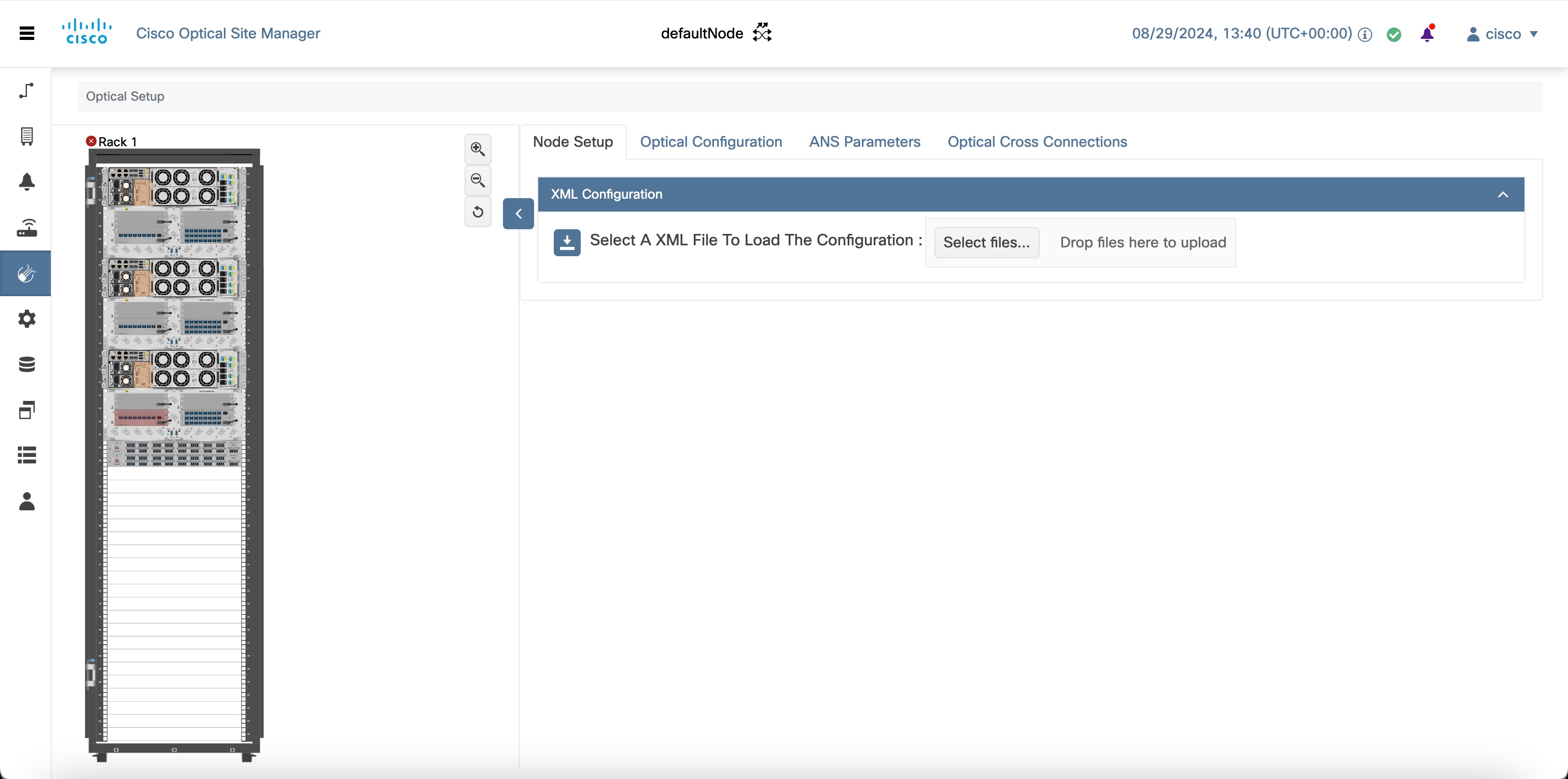
Import a Cisco Optical Network Planner configuration file
Use this task to import a Cisco Optical Network Planner NETCONF file (.xml) into Cisco Optical Site Manager to configure device parameters automatically.
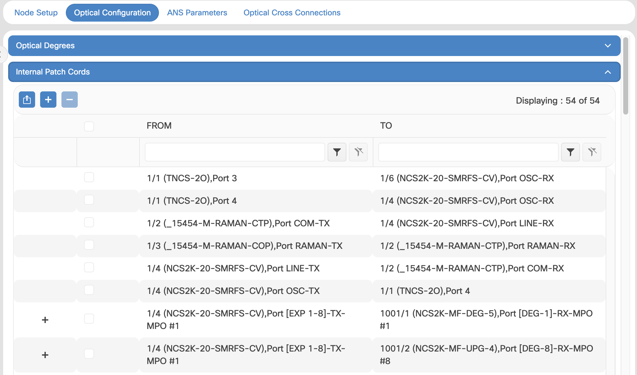
If you have a NETCONF file (.xml) exported from Cisco Optical Network Planner (Cisco ONP), you can import it to Cisco Optical Site Manager. This file includes:
-
Node, shelf, card type, and port information, including wavelength
-
Pluggable Port Module (PPM), OTN, and FEC parameters
-
Degree, IPC, and link-related information
-
Fiber attributes and other network parameters
 Note |
While you will typically upload a Cisco ONP-generated file, there are cases where you must upload the 'golden XML' file provided to you. |

Before you begin
Ensure that:-
The NETCONF file (.xml) contains these parameters available on Cisco Optical Site Manager:
-
device name
-
uid
-
rack id
-
chassis/passive unit id
-
-
Ensure the Cisco Optical Site Manager site name (in the CONP XML file or any other location) does not contain the string IP. If this string appears in the site name, network discovery in Cisco Optical Network Controller does not work correctly.
-
Cisco Optical Site Manager is newly activated with no devices added to it.
-
The Cisco Optical Network Planner configuration file does not include any Optical Cross-Connects.
Procedure
|
Step 1 |
Click Optical Setup in the left panel. |
||
|
Step 2 |
Click the Node Setup tab. |
||
|
Step 3 |
In the Upload Configuration section, click Select a configuration file. |
||
|
Step 4 |
Verify these configuration before adding a device:
|
||
|
Step 5 |
(Optional) To download the device configuration details in an XML file, follow one of these steps:
|
||
|
Step 6 |
Create an authorization group for the device added through the imported XML. For details, see Create or edit an authorization group |
||
|
Step 7 |
Edit the device details: |


 Feedback