In this chapter, "RAMAN-CTP" refers to the 15454-M-RAMAN-CTP card and "RAMAN-COP" refers
to the 15454-M-RAMAN-COP card.
The single-slot RAMAN-CTP and RAMAN-COP cards
support counter and co-propagating Raman amplification on long unregenerated spans.
The cards manage up to 96 ITU-T 50 GHz spaced
channels over the C-band of the optical spectrum (wavelengths from 1528.77 to
1566.72 nm). The counter-propagating RAMAN-CTP card is the primary unit. The
co-propagating RAMAN-COP card is the secondary unit and can be used only when the
counter-propagating unit is present. The OSC pluggable used with the cards is
ONS-SC-OSC-18.0=.
The RAMAN-CTP card can be calibrated either manually or automatically from the
Maintenance tab in the Cisco Optical Site Manager web interface. When the RAMAN-COP
card is used, the RAMAN-CTP card can be calibrated only using the manual option.
The features of the RAMAN-CTP and RAMAN-COP
cards include:
-
Raman section: 1000-mW total pump
power for four pumps and two wavelengths.
-
Embedded distributed feedback
(DFB) laser at 1568.77 nm to be used for optical safety and link continuity (in
RAMAN-CTP card only).
-
Photodiodes to enable monitoring
of Raman pump power.
-
Photodiodes to enable monitoring
of the DFB laser and signal power (in RAMAN-CTP card only).
-
Automatic laser shutdown (ALS) for
optical laser safety.
-
Hardware output signals for loss
of signal (LOS) monitoring at input photodiodes.
-
Raman pump back reflection
detector to check for excessive back reflection.
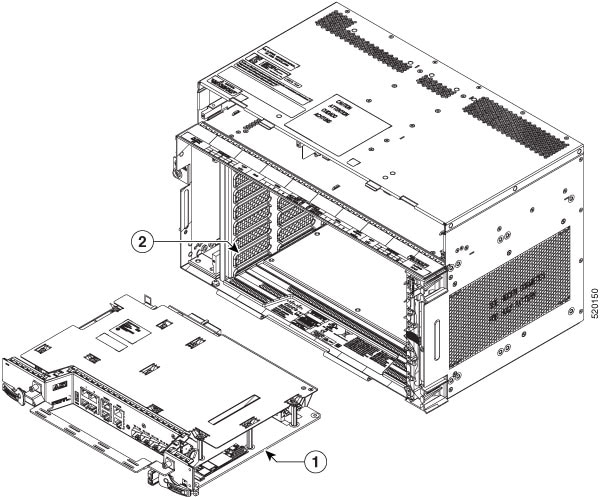
When the node has either RAMAN-CTP or RAMAN-COP card, you can install the card in the
following slots.
-
Slots 2–7 in NCS 2006
-
Slots 2–16 in NCS 2015
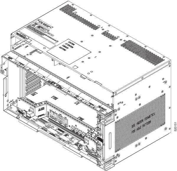
When the node has both RAMAN-CTP or RAMAN-COP cards, you can install the cards in the
following slots.
-
If the RAMAN-CTP card is installed in an even slot, the RAMAN-COP card must be
installed in the next odd slot.
-
If the RAMAN-COP is installed in an even slot, the RAMAN-CTP card must be
installed in the next odd slot.


 Feedback