Cisco NCS 1001 Overview
Cisco NCS 1001 (NCS1001-K9) is 1 RU chassis that addresses the growing bandwidth needs of data center DWDM applications. It provides a DWDM line system that is optimized for data center environments and is optimized for point-to-point applications at maximum capacity. NCS 1001 supports up to three optical modules. The modules can be amplifiers or protection switching modules.
NCS 1001 has the following components:
-
Removable control card
-
Four removable fans
-
Two removable 600W AC/DC or DC/DC power supply modules (PSU)
-
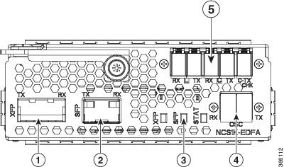
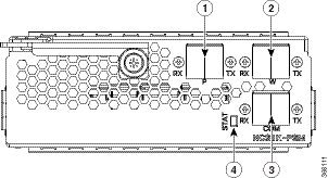
Three slots for optical modules. Two Optical Amplifier Modules ( NCS1K-EDFA) and a Protection Switching Module (NCS1K-PSM) can be inserted in these slots.
The optical modules can be inserted in slots 1 to 3 as shown in the following figure. The optical modules can be inserted and removed from the slots while the system is operational. In amplified configuration, the Optical Amplifier module can be inserted in any slot. In (section) protected configuration, the protect Optical Amplifier module is inserted in slot 1, Protection Switching Module in slot 2, and working Optical Amplifier module in slot 3.
 Caution |
Each optical module must be inserted in a slot only when the module in the adjacent slot is completely inserted and seated or the adjacent slot is empty. If an optical module is inserted in a slot without seating the adjacent module, the ejector might interfere with the adjacent module. |
Caution |
The empty slots must be inserted with the filler optical modules or filler PSUs as appropriate to guarantee safety and system cooling compliance. See Cisco NCS 1001 Front View and Cisco NCS 1001 Rear View to identify the slots for optical modules and PSUs respectively. |
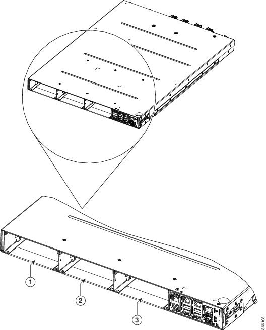
|
1 |
Optical Module Slot 1 |
|
2 |
Optical Module Slot 2 |
|
3 |
Optical Module Slot 3 |
The slot numbers are also specified on the front panel label.
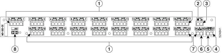
|
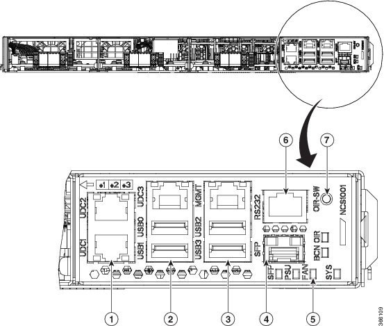
1 |
UDC (user data channel) for optical modules 1 and 2 |
|
2 |
Two USB 2.0 ports and one UDC for optical module 3 |
|
3 |
Two USB 2.0 ports and one 10/100/1000 LAN electrical management interface |
|
4 |
10/100/1000 LAN management interface (optical) |
|
5 |
Status LED (SFP link, Power supply, Fan, System, Beacon, OIR) |
|
6 |
RS232 console port of the control card |
|
7 |
OIR switch |
|
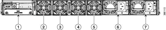
1 |
Control card and SSD (Solid State Disk) |
|
2 |
Fan 3 |
|
3 |
Fan 2 |
|
4 |
Fan 1 |
|
5 |
Fan 0 |
|
6 |
600W AC/DC or DC/DC redundant power supply module (PSU 1) |
|
7 |
600W AC/DC or DC/DC redundant power supply module (PSU 0) |
Both the power supply modules shall be AC/DC or DC/DC. Mixed configuration is not allowed.
Benefits
NCS 1001 provides the following benefits.
-
Up to 23dBm output power to allow for +3dBm per channel fiber launch power and maximum optical performance for high baud rate and higher order modulation format transponders.
-
Switchable gain pre-amplifier up to 34db.
-
Embedded Optical Channel Monitoring (OCM) module to monitor per channel power at all the input and output ports.
-
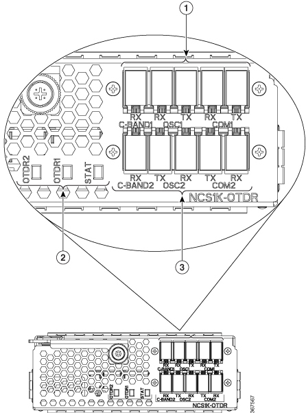
Integrated pluggable optics based OSC and OTDR support.
-
OSC supports user data channel transport as well as remote node management.
-
Supports 96 channels of C-Band in 1 RU.
-
Supports flex grid on OCM module.
Physical Characteristics
-
Width: 17.44” (442.9 mm)
-
Depth: 23.64” (600.5 mm)
-
Height: 1 RU
-
Weight without power supply unit: 8.2 kg
-
Weight with two power supply units: 10.5 kg
-
Weight of AC PSU: 1.162 kg
-
Weight of Fan: 78 gms
-
Weight of control card: 1.5 kg
For information about NCS 1001, see the data sheet.


 Feedback