Cisco Network Convergence System 1001 Data Sheet
Available Languages
Bias-Free Language
The documentation set for this product strives to use bias-free language. For the purposes of this documentation set, bias-free is defined as language that does not imply discrimination based on age, disability, gender, racial identity, ethnic identity, sexual orientation, socioeconomic status, and intersectionality. Exceptions may be present in the documentation due to language that is hardcoded in the user interfaces of the product software, language used based on RFP documentation, or language that is used by a referenced third-party product. Learn more about how Cisco is using Inclusive Language.
Rapid capacity growth in the data center and between data centers has driven the need for cloud-scale networking solutions that allow for quick and simple turn-up with enhanced monitoring, deliver performance optimization for capacity scale through modulation and baud-rate innovations, and effectively support multiple vendors’ transponder solutions. The Cisco® Network Convergence System 1001 (NCS 1001) delivers all this and more. The Cisco NCS 1001 is a dense wavelength-division multiplexing (DWDM) line system that is mechanically optimized for data center environments; is performance optimized for maximum capacity; and provides complete automation of installation and configuration with real-time and fine-grained monitoring.
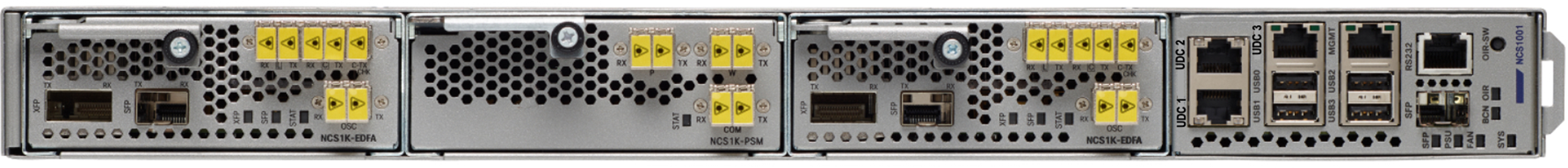
The Cisco NCS 1001 (Figure 1) is a 1RU system that is capable of supporting up to three pluggable modules. The modules can be amplifiers or protection switch modules along with the OTDR. A 96/64/32-channel unprotected point-to-point or a protected point-to-DWDM line system can be implemented with one NCS 1001.
The system operates on a Linux kernel with the carrier-class 64-bit Cisco IOS® XR Software in a Linux container (LxC) and XR system admin plane in a separate LxC. It encompasses a wide variety of features as well as a range of machine-to-machine APIs based on YANG models for ease of configuration and a telemetry agent for a pub-sub model of device monitoring and also provides an infrastructure for third-party applications.
Cisco NCS 1001
The Cisco NCS 1001 system provides the following hardware benefits (also see Figure 2):
● Up to 23dBm output power to allow for +3dBm per channel fiber launch power and maximum optical performance for high–baud rate and higher order modulation format transponders
● Switchable gain preamplifier up to 34dB
● Embedded Optical Channel Monitoring (OCM) module to monitor per channel power at all the input and output ports
● Integrated pluggable optics-based OSC
● OSC support for user data channel transport as well as remote node management
● Unmatched scale and density: line system for 96/64/32 channels of C-band in 1RU
● Flex-grid support on OCM module
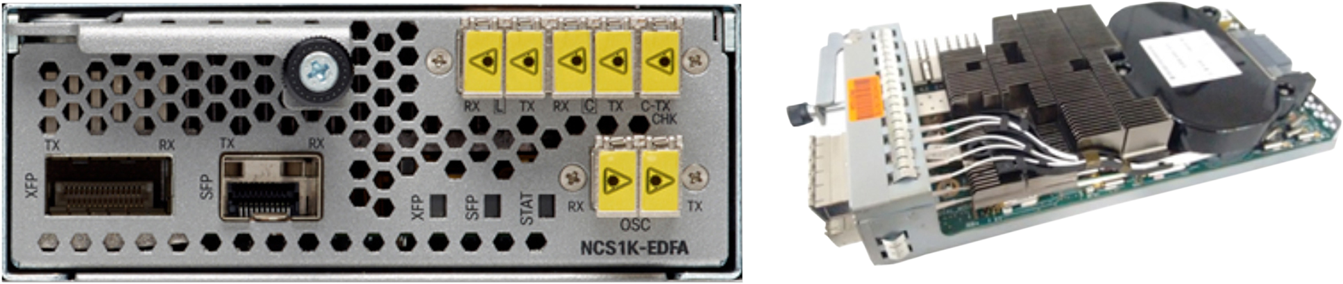
NCS1K-EDFA Module
The amplifier module provides the following ports:
● OSC SFP slot
● LINE-TX and RX ports
● COM-TX and RX ports
● COM-TX check port
Figure 3 is a functional block diagram of the amplifier module.
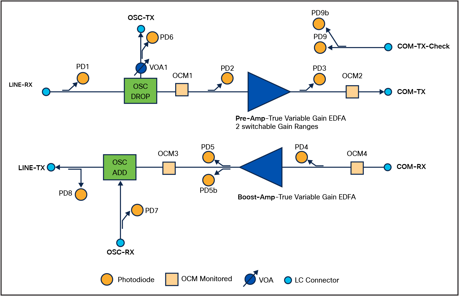
NCS1K-EDFA Functional Block Diagram
The NCS 1K-EDFA module, which can be used as both the Terminal as well as the ILA, provides the following functionality:
● Preamplifier (LINE-RX to COM-TX)
◦ Single preamplifier variant, with switchable gain ranges, according to link loss:
◦ Range 1 – Normal : 0 to 24dB gain, with tilt control; 24 to 27dB gain, with tilt uncontrolled
◦ Range 2 – Extended : 20 to 34dB gain, with tilt control; 34 to 37dB gain, with tilt uncontrolled
◦ Total 23dBm output power at COM-TX port
● Booster (COM-RX to LINE-TX)
◦ A true variable gain booster amplifier
◦ Gain range: 1 to 20; 20 to 25 uncontrolled tilt.
◦ Total 23dBm output power at LINE-TX port
● Add/drop OSC channel support both 1510nm and 1610nm +/–10nm and are the following:
◦ ONS-SE-155-1510
◦ CWDM-SFP-A610
◦ CWDM-SFP-1510
◦ ONS-SC-Z3-1610
◦ ONS-SC-Z3-1510
● OCM assesses channel presence and gain regulation and per channel power monitoring
Various Amplifier modes supported
Users can configure the amplifiers in the following manner.
The amplifier module can be set to manual or autoconfiguration mode. The default mode is manual.
In manual mode, the user sets gain and tilt on the amplifier. In this mode, the OCM data is not reported on the CLI, but the raw data can be exported. If the user selects auto mode, the user needs to configure the grid (50Ghz/75GHz/100Ghz/flex) and the per channel power (default +1dBm). OCM data will be reported on the CLI as per grid definition.
Auto mode allows a user with a basic understanding of the optical performance of the link to set up the DWDM system with minimum clicks/effort.
The Cisco NCS 1001 OTDR Line Card (Figure 4) occupies one slot in the 1RU NCS 1001 Line System platform. The module provides two bidirectional OTDRs and corresponding filters to combine the OTDR signals with the OSC and C-Band channels.
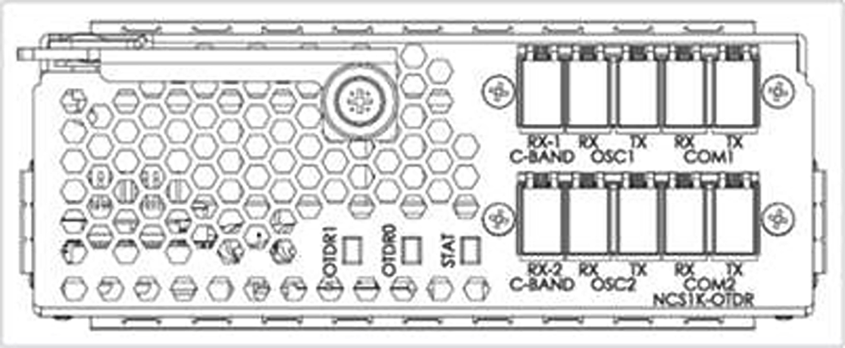
Cisco NCS 1001 OTDR Line Card front view
The Cisco NCS 1001 OTDR Line Card provides the following benefits:
● Bidirectional OTDR up to 100 km. The OTDR operates inline and in real time with no interruption to traffic.
● Embedded filter for combining OTDR with OSC and C-Band channels.
● Multiple deployment models can be supported—terminal, ILA, and standalone.
● Compact one-third of an RU. Up to 6x OTDRs in one RU.
● Auto-mode and expert modes available depending on what the user requires.
The NCS1K-PSM module (Figure 4) provides the following ports:
● COM-TX and RX ports
● W-TX and RX ports
● P-TX and RX ports

NCS1K-PSM Module
Figure 6 is a functional block diagram of a protection switch module.
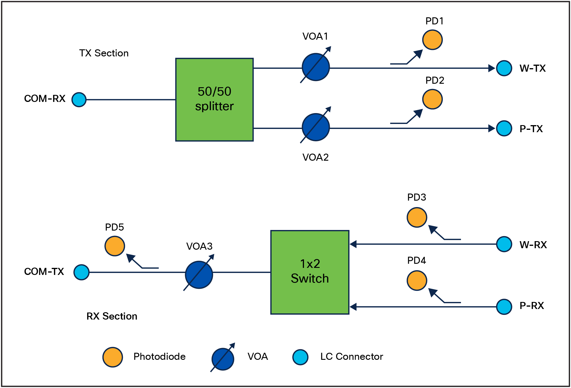
NCS1K-PSM Functional Block Diagram
The PSM module provides the following features:
● In TX section:
◦ Splits input optical channels to both working and protection lines.
● In RX section:
◦ Selects the signals from working or protection line. Each line is monitored through a Photo Diode.
◦ Balance the two line losses by changing the VOA attenuation value at the same time as the switch change of state.
● The PSM can be operated in bidirectional switching mode or unidirectional switching mode. In unidirectional switching mode, the following behavior is to be expected:
◦ Splitter on the PSM is bypassed.
◦ Selector on receiver decides what signal to use. If switchover is initiated, PSM does not signal to remote end.
A typical 96-channel 50Ghz spaced point-to-point DWDM system would include 12x NCS 1004 units, 1x MD48-ODDE filter, 1x MD48-EVENE filter, 1x MD48-CME coupler, and 1x NCS 1001. Upto 28Tbps of capacity would consume only 29RU of rack space. Similarly, with MD64 channel spaced 75GHz point-to-point DWDM system would include 8x NCS 1004 units, 1x MD32-ODDE filter, 1x MD32-EVENE filter, 1x MD32-CME coupler, and 1x NCS 1001. Upto 38Tbps of capacity would consume only 19RU of rack space and the MD32 channel spaced 150GHz point-to-point DWDM system would include 4x NCS 1004 units, 1x MD32-EVENE filter, and 1x NCS 1001. Upto 38Tbps of capacity would consume only 10RU of rack space.
The two primary configurations supported with the NCS 1001 are the unprotected point-to-point system and the protected point-to-point system. As illustrated in Figure 7, the unprotected configuration requires one amplifier module (NCS1K-EDFA) plugged into the NCS1001-K9 box. OSC add-drop and bidirectional amplification is performed by this module.
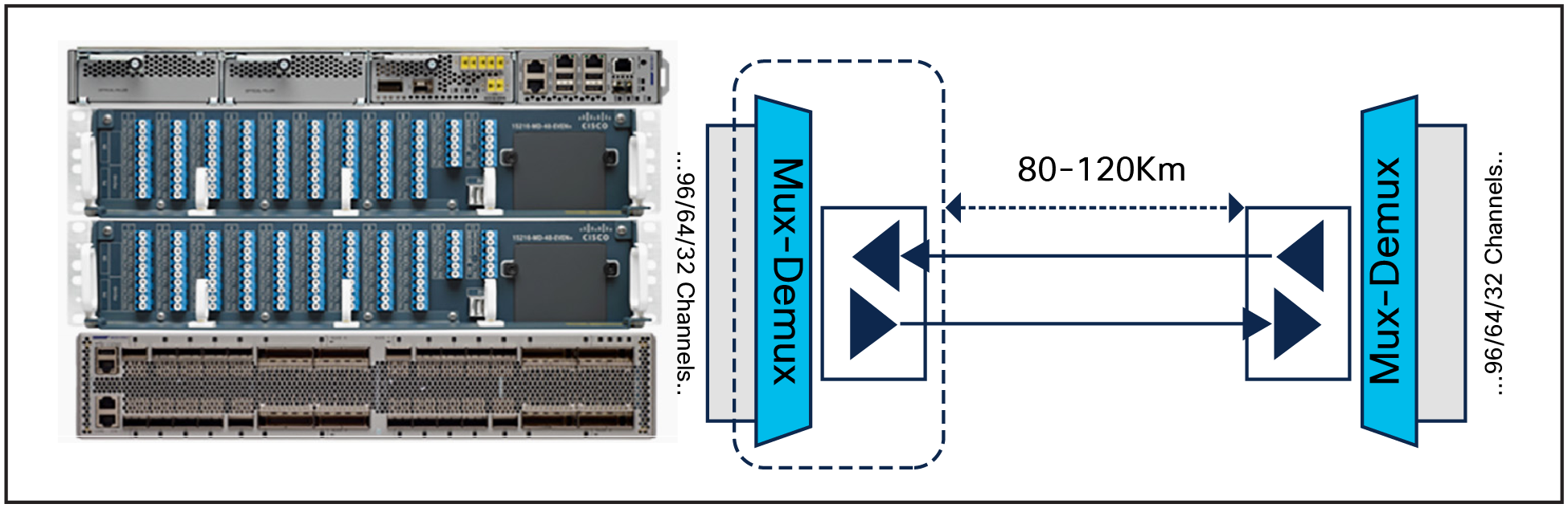
Unprotected Point-to-Point DWDM Line System with NCS 1001
In a protected system, one protection switch module (NCS1K-PSM) and two amplifier modules (NCS1K-EDFA) need to be plugged into an NCS1001-K9 box. The PSM module splits the traffic onto fiber paths, and the far end selects better signal based on optical receive power, thereby providing optical power-based section protection. (See Figure 8.)
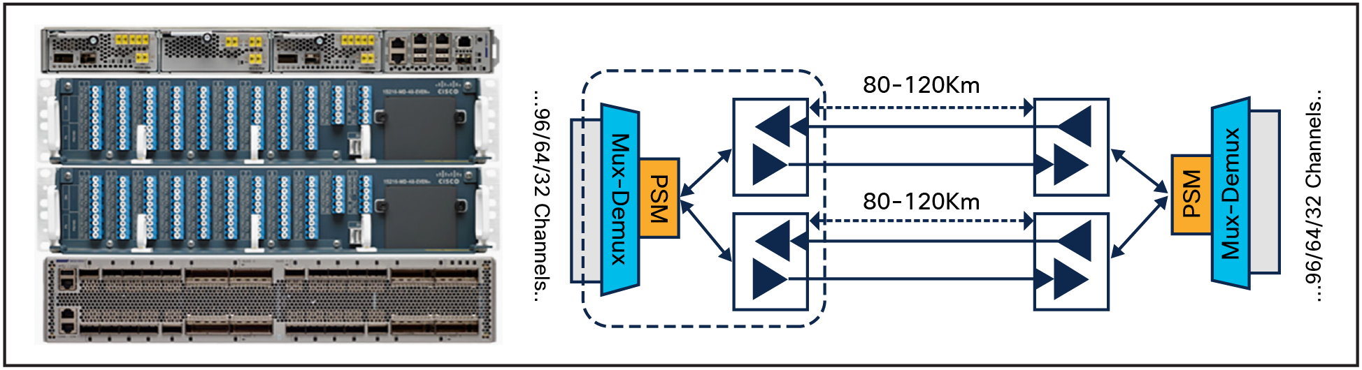
Protected Point-to-Point DWDM Line System with NCS 1001
The Cisco NCS 1001 provides comprehensive management capabilities to support operations, administration, maintenance, and provisioning (OAM&P) capabilities through Cisco IOS XR Software CLI, SNMP, Syslog, and XML. In addition, iPXE for automated software download and zero-touch provisioning (ZTP) for automated configuration download are available for simplified installation. For machine-to-machine configuration and management of NCS 1000, different YANG based transport options are available – NETCONF and gRPC. These can be used over JSON, XML or GPB encoding. The NCS 1000 provides a set of native YANG models as well as the ability to map into any industry-standard or customer-defined YANG models. For monitoring, NCS 1000 provides a streaming telemetry feature that relies on a push mechanism to disseminate user-selected Performance Monitoring and status information at user-specified frequencies at granular 30-second intervals. This improves monitoring speed and scale compared to traditional pull-based mechanisms such as SNMP. Today, the NCS1001 COSM and CONC is supported through the NCS1014 management interface and this feature is enabled from 24.3. However, the native COWSM/CONC support on NCS1001 will be made available soon.
The Cisco NCS 1001 supports both transparent and nontransparent signal transport performance monitoring. Calculation and accumulation of the performance-monitoring data are supported in 15-minute and 24-hour intervals as per G.7710.
Each port incorporates LEDs to provide a quick visual check of the operational status of the card.
The headless operation allows for the NCS 1001 data plane to operate errorless during software upgrades and when the controller card is either physically absent or in a failed state. All line card statistics will be accumulated and will be available to the user after the controller is up.
Table 1 summarizes the features of the NCS 1001.
| Feature |
Description |
| Software compatibility |
● Cisco IOS XR Software 6.2.1 or later
|
| Optical feature summary |
● +23dBm output power
● Up to 34dB of preamplifier gain
● Switchable preamplifier gain range
● OCM module for per channel power monitoring at COM and line ports
● Tx and Rx power monitoring
● Line protection
● OSC and OTDR support
● Embedded SSDs (both in chassis and controller)
|
| Availability |
● Online insertion and removal of the controller
● Headless mode of operation
|
| Network management |
● iPXE and ZTP
● Cisco IOS XR Software CLI
● SNMP
● Streaming telemetry
● NETCONF, gRPC with YANG data-models incl. Open Config.
|
| Physical dimensions (NCS1001-K9) |
● Occupies 1RU and fits into 2- or 4-post 19-inch, 21-inch, and 23-inch racks
● Weight: 20 Pounds / ~9Kgs
|
| Power |
● <200W
|
| Physical summary |
● Front-to-back straight-through airflow
● 600W DC PSU
● 600W 100/127VAC 200/240VAC 10A AC PSU
● 1+1 FRU AC and DC power
● 3+1 FRU fans
● FRU controller
● 1 console
● 1 RJ45 and 1 GE SFP management port
● 3 USB2.0 3A
● 3 RJ45 UDC (user data channel) ports
● System, trunk, client, fan PSU, locator beacon LEDs
|
| Environmental conditions |
● Operating temperature: –5 to 55°C
|
Table 2 lists regulatory compliance information for the trunk card. Note that all compliance documentation might not be completed at the time of product release. Check with your Cisco sales representative for countries other than Canada, the United States, and the European Union.
Table 2. Regulatory Compliance
| ANSI System |
ETSI System |
| Countries and Regions Supported |
|
|
● Canada
● United States
● Korea
● Japan
● European Union
|
● European Union
● Africa
● CSI
● Australia
● New Zealand
● China
● Korea
● India
● Saudi Arabia
● South America
|
| EMC Emissions |
|
|
● ICES-003 Class A
● AS/NZS CISPR 22 Class A
● CISPR 22 Class A
● EN55022 Class A
● FCC 47CFR15 Class A
|
● VCCI Class A
● K32 Class A
● CNS 13438 Class A
● EN61000-3-2 Power Line Harmonics
● EN61000-3-3 Voltage Changes, Fluctuations, and Flicker
|
| Safety |
|
|
● CSA C22.2 #60950-1 - Edition 7, March 2007
● UL 60950-1 - Edition 2, December 2011
|
● IEC 60950-1 Information technology equipment Safety Part 1: General requirements - Edition 2, 2005 + Amendment 1 2009
● EN 60950-1: Edition 2 (2006) Information technology equipment - Safety - Part 1: General requirements + A11:2009 + A1:2010 + A12:2011
● 62368-1
● CE Safety Directive: 2006/95/EC
|
| EMC Immunity |
|
|
● ICES-003 Class IEC/EN61000-4-2 Electrostatic Discharge Immunity
● IEC/EN61000-4-3 Radiated Immunity
● IEC/EN61000-4-4 EFT-B Immunity
● IEC/EN61000-4-5 Surge
|
● IEC/EN61000-4-6 Immunity to Conducted Disturbances
● IEC/EN61000-4-11 Voltage Dips, Short Interruptions, and Voltage Variations
● K35
|
| ETSI/EN |
|
|
● EN 300 386 Telecommunications Network Equipment (EMC)
● EN55022 Information Technology Equipment (Emissions)
|
● EN55024/CISPR 24 Information Technology Equipment (Immunity)
● EN61000-6-1 Generic Immunity Standard
|
| Laser |
|
|
● 21CFR1040 (2008/04) (Accession Letter and CDRH Report) Guidance for Industry and FDA Staff (Laser Notice No. 50), June 2007
|
● IEC 60825-1: 2007 Ed. 2.0 Safety of laser products Part 1: Equipment classification, requirements and users guide
● IEC60825-2 Ed.3.2 (2010) Safety of laser products Part 2: Safety of optical fibre communication systems
|
| Optical |
|
|
● ITU-T G.691
|
● ITU-T G.975
|
| Quality |
|
|
● TR-NWT-000332, Issue 4, Method 1 calculation for 20-year Mean Time Between Failure (MTBF)
|
|
Table 3 provides NCS 1001 specifications, and Table 4 provides ordering information.
Table 3. NCS 1001 Specifications
| Management |
||
| Beacon LED |
Blue |
|
| Client and DWDM port LEDs
● No alarms
● Minor alarms
● Critical and major alarms
|
Green Amber Red |
|
| Fan LED
● All 4 fans are present and running
● One or more fans are absent or failed
|
Green Red |
|
| PSU LED
● At least 1 PSU present and operational
● 2 PSUs are present, but one has no power
|
Green Red |
|
| Status LED
● No active system alarms
● Presence of major or minor alarms
● Presence of critical alarms
|
Green Amber Red |
|
| Power fully loaded (including pluggable) |
Protection Configuration |
Unprotected Configuration |
|
● Typical
● Maximum
|
250W 300W |
200W 250W |
| Physical |
||
| Dimensions |
NCS1001-K9: 17.5” wide x 23.6” deep x 1.73” tall NCS1K-EDFA: 4.2” wide x 9.4” deep x 1.5” tall NCS1K-PSM: 4.2” wide x 9.4” deep x 1.5” tall NCS1K-2KW-DC: 2.9”wide x 10.4” deep x 1.5” tall NCS1K-2KW-AC2: 2.9”wide x 10.4” deep x 1.5” tall NCS1K1-FAN: 1.57” wide x 4.13” deep x 1.57” tall NCS1K-CNTLR2: 6.4” wide x 11” deep x 1.1” tall |
|
| Weight |
NCS1001-K9: 8.2 Kg / ~18 Pounds (including fans, SSD, and CNTLR) NCS1K-EDFA: 0.84Kg / ~1.85 Pounds NCS1K-PSM: 0.42Kg / ~0.92 Pounds NCS1K-2KW-DC: 1.2Kg / ~2.64 Pounds NCS1K-2KW-AC2: 1.2Kg / ~2.64 Pounds NCS1K1-FAN: 0.08Kg / ~0.17 Pounds NCS1K-CNTLR2: 1.5Kg / ~3.3 Pounds |
|
| Storage temperature |
-28°C to 70°C (–20°F to 158°F) |
|
| Operating temperature: normal |
-5°C to 55°C (23°F to 131°F) |
|
| Relative humidity
● Normal
● Short-term
1
|
5% to 85%, noncondensing 5% to 90% but not to exceed 0.024kg water/kg of dry air |
|
| Part Number |
Description |
| XR-NCS1K-621K9 |
NCS 1000 Cisco IOS XR Software Release 6.2.1 RTU - USB key |
| NCS1001-K9= |
Network Convergence System 1001 line system 3 slots |
| NCS1K-2KW-DC= |
Network Convergence System 1001 2KW DC PSU |
| NCS1K-2KW-DC-CBL= |
NCS1K DC cable with connector |
| NCS1k-2KW-AC2= |
Network Convergence System 1001 2KW AC PSU 2 |
| NCS1K-2KW-AC-CBL= |
NCS1K AC IEC C15 to NEMA L6-20P cable |
| CAB-TA-NA= |
North America AC Type A Power Cable |
| NCS1K1-FAN= |
Network Convergence System 1001 line system fan |
| NCS1K-CNTLR2= |
Network Convergence System 1001 controller 2 |
| NCS1K-PSM= |
Network Convergence System 1001 protection module |
| NCS1K-EDFA= |
Network Convergence System 1001 amplifier module |
Flexible payment solutions to help you achieve your objectives
Cisco Capital makes it easier to get the right technology to achieve your objectives, enable business transformation and help you stay competitive. We can help you reduce the total cost of ownership, conserve capital, and accelerate growth. In more than 100 countries, our flexible payment solutions can help you acquire hardware, software, services and complementary third-party equipment in easy, predictable payments. Learn more.
| New or Revised Topic |
Described In |
Date |
| Remove pointers to Restconf support |
April 13, 2026 |
|
| Updated Figure 3 NCS1K-EDFA Functional Block Diagram with no tilt in Pre-Amp |
April 28, 2025 |
|
| Inserted OTDR Section |
April 28, 2025 |
|
| Included the MD64 and MD32 solutions along with MD96 |
April 28, 2025 |
|
| Updated Table 1 Physical summary section |
April 28, 2025 |
|
| Inclusion of North America power cable |
April 28, 2025 |