The documentation set for this product strives to use bias-free language. For the purposes of this documentation set, bias-free is defined as language that does not imply discrimination based on age, disability, gender, racial identity, ethnic identity, sexual orientation, socioeconomic status, and intersectionality. Exceptions may be present in the documentation due to language that is hardcoded in the user interfaces of the product software, language used based on RFP documentation, or language that is used by a referenced third-party product. Learn more about how Cisco is using Inclusive Language.
CPC allows service providers to create policies that are customized to their particular business requirements through the
use of the CPC Policy Builder, a web-based tool with a graphical user interface (GUI) that allows for rapid development of
innovative new services.
The Policy Builder GUI supports both configuration of the overall CPC cluster of virtual machines (VMs) as well as the configuration
of services and advanced policy rules. These sections introduces the main aspects of the PB GUI as laid out in three tabs
on the upper right of the interface: Reference Data, Services and Policies.
Reference data
A reference data item is a system configuration element that
provides access for configuring various aspects of the system to prepare it for operation
supplies settings and parameters referenced by policy rules across multiple services, and
enables reuse of configuration options such as account balances and notifications by different services as needed.
Reference data configuration options
The Reference Data tab contains static system, network, and template definitions. It is not directly related to policy, services,
or use cases, but defines the reference points for the following types of information:
Systems, cluster, and instance data
Jdbc query string definitions
Balance and quota definitions
Diameter configuration, and CPC (Rest API - 5G) configuration
Query strings
Custom reference data tables (custom look up tables such as apn names)
Notification addresses and text templates
Policy reporting criteria
Subscriber data repositories
Services
The creation of a new service begins with creating a Use Case Template (UCT) for the service. UCTs consist of Service Configurations
that are specific to the service being created. For example, a Service Configuration might set up a Gx Rule or Basic QoS.
The UCT is also used to configure Use Case Initiators (UCI), which are instructions describing when a specific Service Configuration
should be in effect. An example of a UCI is only send this Gx Rule when the account balance is depleted. Multiple UCIs can
be configured for each Service Configuration. This enables complex logic that determines when the configuration is active
or inactive.
Once a UCT and associated UCIs are defined, it becomes the basis for Service Options, which are specific instances of the
UCT that are populated with data specific to the service. Multiple Service Options can be created from a single UCT; for example,
a UCT that provides for passing QoS parameters can be reused with different QoS values for different customers. Multiple Service
Options can be layered to create the end Service.
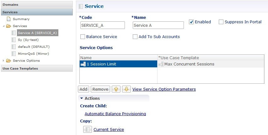
Figure 1. Services tab
The Domains panel within the Services tab handles the initial interaction of the client device with the policy engine, and
covers tasks including client authentication, default provisioning of unknown clients and qualifying a client for particular
system defaults and services.
Policies
Within the various Extension Points are Policies that define Conditions (events and data from the policy flow and external
systems) that can then trigger Actions (manipulation of data and communication back to external systems).
Note that the configuration of services for most deployments will be handled through use of the Reference Data and Services
tabs; advanced policies as defined on the Policies tab and discussed above are only required for complex deployments. It is
recommended that only experienced users access the Policies tab as errors in custom policies can have negative impact on the
operation of the system. Detailed discussion of custom policies is outside of the scope of this document.
By default, the Policies and Blueprint tabs are disabled.
Important
The Policy Builder offers the Blueprint section under Policies tab to enable Cisco recommended changes to the Policy Engine. Changes made without Cisco guidance are not supported and can
result in poor performance, platform instability, or reduced capacity.
Enabling Policies tab
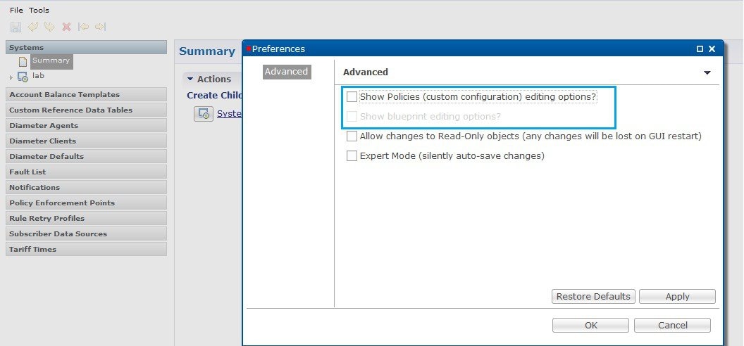
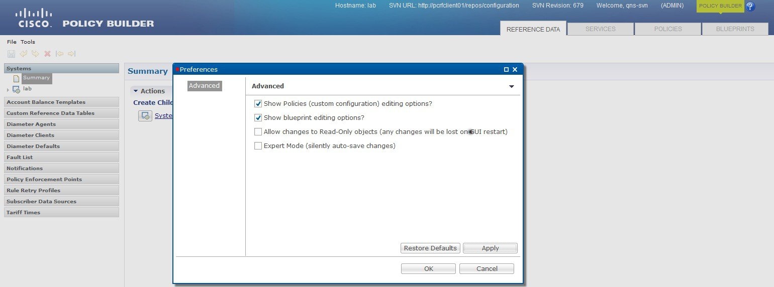
In Policy Builder, Tools > Preferences to open Preferences pop-up window.
Figure 2. Preferences - Policies
Select Show Policies (custom configuration) editing options? and click Apply.
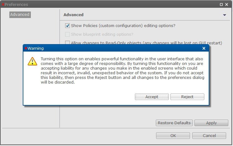
Warning pop-up dialog box opens up.
Figure 3. Warning
Click Accept so that POLICIES tab is visible in Policy Builder.
Enabling BLUEPRINTS tab
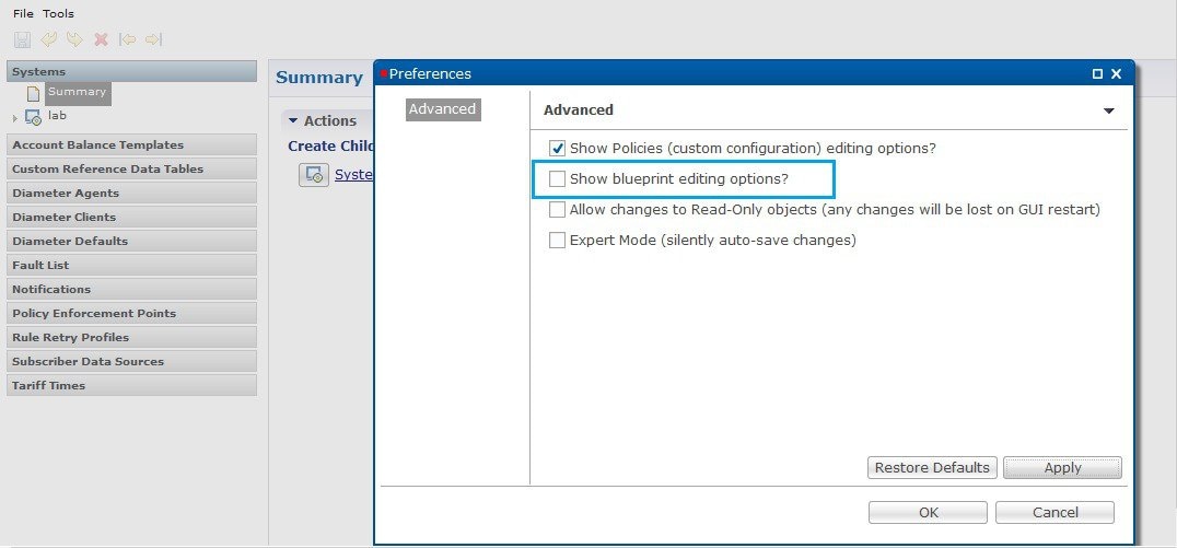
For BLUEPRINTS tab to be visible in Policy Builder, Show Policies (custom configuration) editing options? must be checked.
Select Show blueprint editing options? and click Apply.
Click Accept so that BLUEPRINTS tab is visible in Policy Builder.
Note
In case the POLICIES checkbox is unchecked while BLUEPRINTS checkbox is checked, the BLUEPRINTS checkbox is unchecked forcefully and the BLUEPRINTS tab is not visible.
Summary of Policy tab capabilities
This reference provides an overview of the Policy tab capabilities, focusing on conditional rules, action triggers, and session
data evaluation for policy decisions and service data return.
Conditional rules within specified Extension Points (Condition/Action)
Trigger specific actions from an extensive catalog of Use Case Initiators
Evaluate and manipulate session data as part of making policy decisions and returning services data to downstream systems
Advantages
Allows for handling complex policy situations without writing custom code.
Support for custom or unusual business rules,
Considerations for building custom policies
Building custom policies requires a deep understanding of the call flow and underlying CPC platform.
Due to the flexibility of the Policy Builder, it is possible to create conflicting policies that can have a negative impact
on system performance.
Accessing the Policy Builder
The Policy Builder is the web-based client interface for the configuration of policies to the Converged Policy and Charging.
Initial accounts are created during the software installation with the default CPC install username as qns-svn and password as cisco123.
URL to access Policy Builder Interface:
For HA: https://<lbvip01>:7443/pb
CPC enables users to be aware of its current privileges while accessing Policy Builder as described below:
If a user has read-write privilege then ADMIN is displayed adjacent to user name in the GUI.
If a user has read-only privilege then READONLY is displayed adjacent to user name in the GUI.
The hostname is displayed in the login dialog box and system banner to differentiate between open windows while performing
any operation of the CPC system. It indicates which system is being modified and prevents any errors or misconfigurations.
The hostname is displayed when the parameter -Dhostname=lab is configured in pb/qns.conf files. If it is not configured in the qns.conf file, it is displayed as a result of the command "hostname" on the server.
The hostname is displayed in the login panel only when the following argument is set to true:
-DshowSitenameLogin
Enable TACACS+ authentication for Policy Builder by enabling PAM authentication (set -DdisablePAMAuthentication to false)
and enabling TACACS+ along with tacacs_on_ui flag set to true in Configuration.csv file.
Policy Builder Field Value Validation
When you start the Policy Builder, the last recorded valid value defined in the eCore is set as the default value. If the
value is not set in the eCore, the valid value is taken based on the eCore data type. For numeric data types, the Policy Builder
displays 0 as a default value. For string data types, the Policy Builder displays null (empty) as a default value.
The Policy Builder validates the value that is configured in the field.
When you enter a value in the field and the value passes validation, the newly entered value is recorded as the last valid
value. If the validation fails, the last recorded valid value is reverted.
Tarrif of the day
Feature description
Table 1. Feature description
Feature Name
Release Information
Description
Tariff of the day
2026.03.0
The Tariff of the Day feature allows service providers to define and apply variable billing rates and different data rules
for specific time intervals. This feature supports dynamic quota management and precise cost control. Service providers benefit
from automated, time-based rate switching, which ensures subscribers are billed accurately based on pre-defined tariff periods.
Tariff Times
Tariff Times refers to the PCF terminology that defines rate structures and their applicable time periods. To determine the
current TariffSwitchTime, Balance uses the current time, based on the time zone specified in the tariff time reference data
configuration. It then checks each switch time from top to bottom to determine whether the current time matches a TariffSwitchTime.
The Policy Control uses the first tariff switch time that matches, including any associated valid dates or a holiday date.
The tariff switch time marks the end of the current tariff period. The system calculates the next tariff switch time by adding
one second to the end of the current tariff switch time and then searching each tariff switch time from top to bottom to find
the next match.
Rates
Rates allow service providers to change how quota is billed to customers. Typically, there is a one-to-one relationship: if
a customer uses 1 MB, they are charged $1 for that usage. Service providers can modify the rate to alter the cost subscribers
pay for their quota usage. For example, with a rate of 0.25, the quota is billed at 1 MB for every 4 MB used. With a rate
of 2, quota usage is billed at 2 MB for every 1 MB the customer uses.
The rate is specified when the system makes a reservation. The default rate is 1.
Tariff Times configuration- Rate specific usecase
This section explains how to set up rates for components that use Autowire Balance. Autowire Balance is the default blueprint
for Balance. You must configure it in the Policy Builder for use in the base system setup. Autowire Balance extends the main
system blueprint.
Complete these steps to configure tariff times and balance rates in the Policy Builder:
Procedure
Step 1
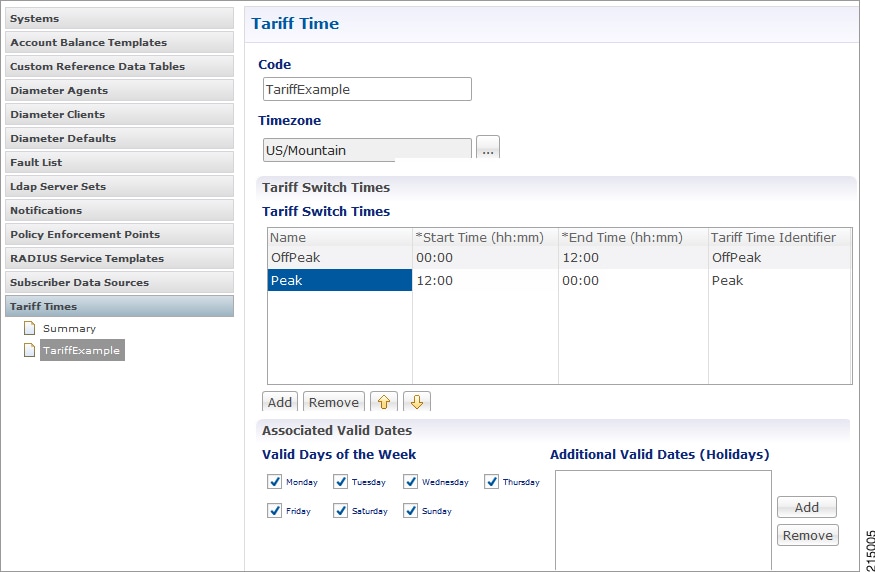
Configure tariff times:
Navigate to Reference Data > Tariff Times.
Create a new child entry and set the time zone if required.
Define rows that cover a full 24-hour period.
Note
A start time of 00:00 (midnight) is inclusive, while an end time of 00:00 is exclusive. Using 00:00 as the end time ensures
the system accounts for all 86,400 seconds (24 hours) in a day.
Figure 6. Tarrif Time
Step 2
Configure balance rate settings:
Navigate to Service > Use Case Templates.
Click Add in Service Configuration and select BalanceRateConfiguration.
Choose an Account Balance Template.
Step 3
Configure rate parameters:
In the Rates List, select a Tariff Switch Time (Key).
Modify the rate as needed.
Click Add Child to add additional rate options.
Step 4
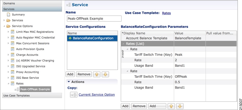
Configure service options:
Navigate to Services > Service Options > Rates.
Click Create Child Service Option.
Click Add in Service Configuration and select BalanceRateConfiguration.
Figure 7. Service Option
Step 5
Choose File > Publish to Runtime.
Tariff Times configuration - TimeOfDay (ToD) usecase
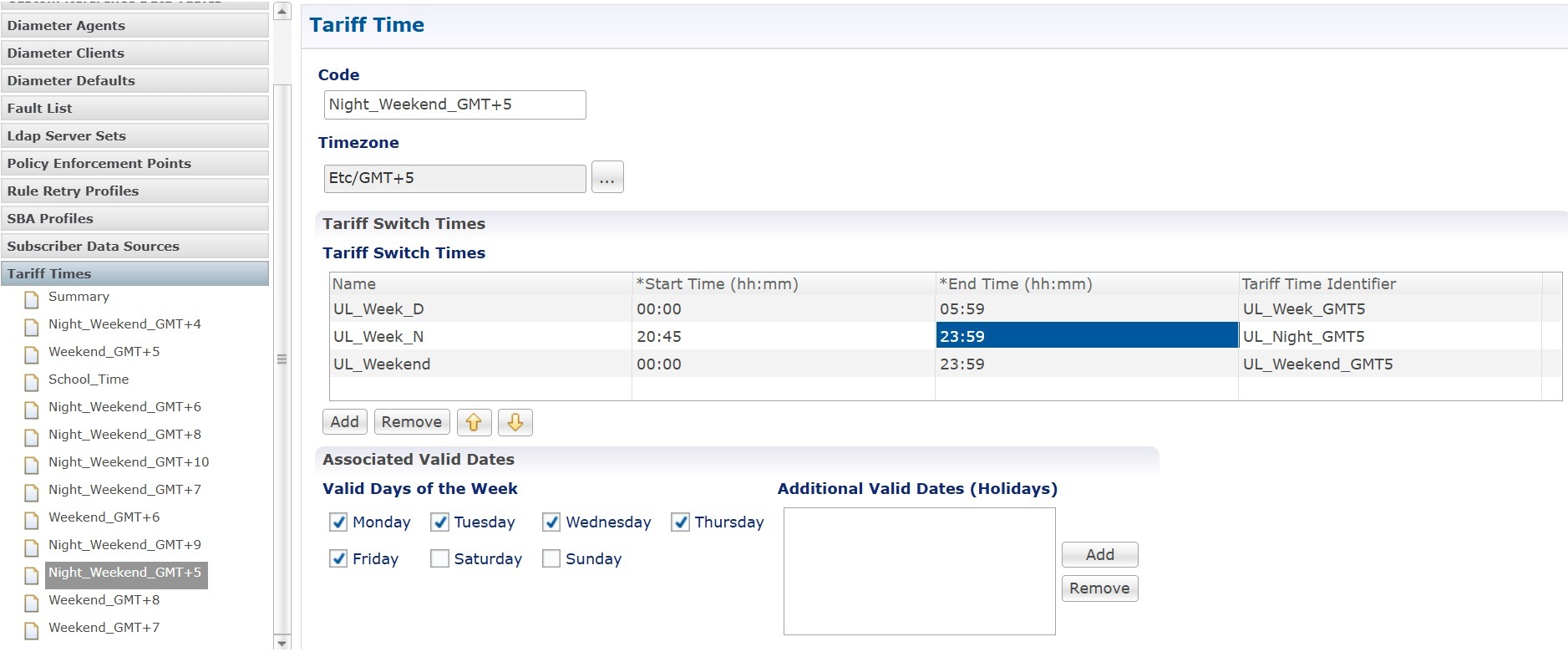
By using Tariff Time configs, CPC also can install/uninstall the TimeOfDay Rules for the subscriber [ex. Unlimited Data Usage
Rules during night or weekend ] using Tariff Switch Times configuration. Sample configuration given below.
Complete these steps to configure tariff times and TimeofDay in the Policy Builder:
Procedure
Step 1
Configure tariff times:
Navigate to Reference Data > Tariff Times.
Create a new child entry and set the time zone if required.
Define rows that cover a full 24-hour period.
Note
A start time of 00:00 (midnight) is inclusive, while an end time of 00:00 is exclusive. Using 00:00 as the end time ensures
the system accounts for all 86,400 seconds (24 hours) in a day.
Figure 8. Tarrif Time
Step 2
Configure TimeofDay rate settings:
Navigate to Service > Use Case Templates.
Click Add in Service Configuration and select TimeofDay.
Step 3
Select a Tariff Switch Time (Key).
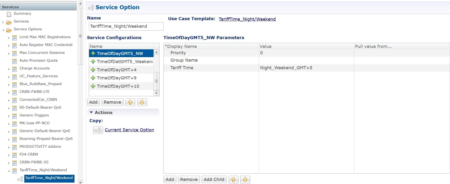
Navigate to Services > Service Options > TimeofDay, click Create Child Service Option, and select TimeofDay in the Service Configuration.
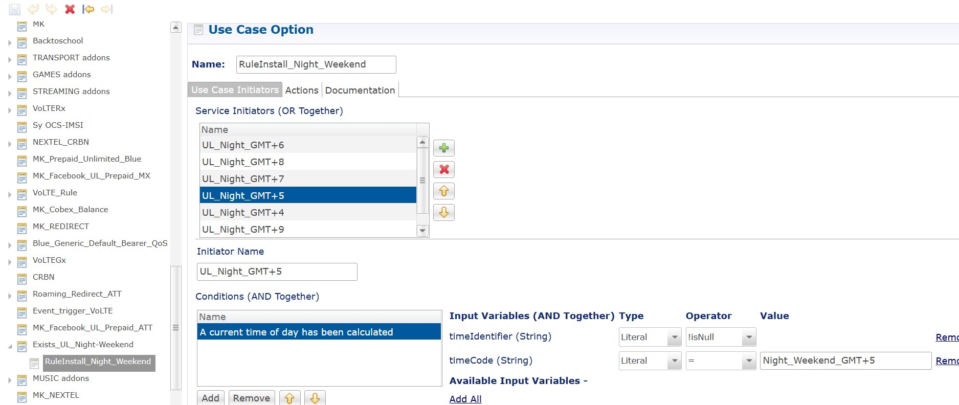
Click Add Child to add one more Use Case Template to install Rule based on condition.
Add condition to match Tariff Time Codewhich is mentioned in the Tariff Times Reference Data.
Step 4
Configure service options:
Navigate to Services > Service Options > TarrifTime Service option.
Click Create Child Service Option.
Click Add in Service Configuration and select TimeofDay Configuration.
Figure 9. Service Option
Figure 10. Use Case Option
Step 5
Choose File > Publish to Runtime.
Edge cases
It is strongly recommended that Tariff Switch Times cover all times during a 24 hour period and do not have gaps. Some customers
use a default Tariff Switch Time entry that covers all the other times that have not been specifically defined.
Tariff Times are not allowed to cross over the midnight boundary for a given day. In practice, this means that often 2 or
more tariff switch times must be created to cover a single logical period. For Example:
Edge case examples
Table 2. Edge case examples
Name
Start Time
End Time
Tariff Time Identifier
Nights Before Midnight
17:00
00:00
NIGHT
Nights After Midnight
00:00
07:00
NIGHT
Days
07:00
17:00
DAY
If a Tariff Switch occurs during a daylight savings time forward switch (i.e. between 2:00am and 3:00am during 'Spring Forward'
in March), an error will occur in processing during that time since that hour is lost. Therefore, it is recommended that switch
times NOT occur during these times on those days.
Gx based quota management
Overview
CPC supports Usage-Monitoring over Diameter Gx interface with different Balance Code, Dosage and monitoring level. Usage monitoring
key Identifies the usage monitoring control instance.
Policy Builder configuration
Procedure
Step 1
Login to CPC Policy Builder.
Step 2
Configure the Account Balance Templates in the Reference Data tab. For more information, see Account Balance Templates.
Step 3
Select the Services tab, and then click Use Case Templates > Summary.
Step 4
Click Use Case Template link from the right side under Create Child to create a use case template.
Enter the name for use case template. For example, name the new template as UsageMonitoringKey.
Click Add under Service Configurations.
Select Service Configuration dialog box opens, and all of the service configuration objects that are available are listed.
Scroll down to the gx area in the list of service configuration objects, and select the required usage monitoring object. For example, UsageMonitoringKey.
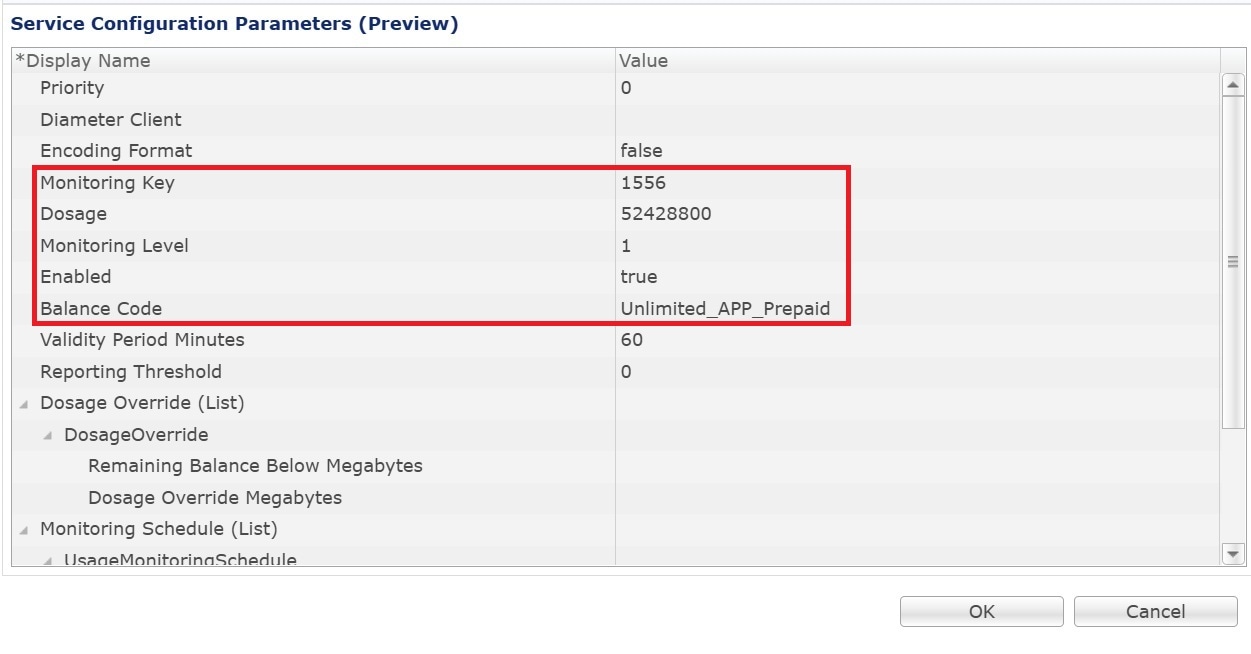
Select Balance Code in the UsageMonitoringKey parameter. Add other parametes as per the reference image. Map this Balance Code to the previously
created Account Balance Template.
Figure 11. Usage monitoring schedule
Step 5
In the left pane of the Services tab, click Services > Service Options to create a service option and add the UsageMonitoringKey use case template.
Step 6
In the left pane of the Services tab, click Services > Services to create a service and add the configured UsageMonitoringKey use case template.

 Feedback