Advanced Service Configurations

Overview

In CPC, reference data is considered information that is needed to operate the policy engine, but not used for evaluating policies. For example, in the Reference Data tab in CPC, are the forms used to define systems, clusters, and instances, and to set times and dates used for tariff switching. The policy engine needs to refer to this data only to process policies correctly. However, the data does not define the policy itself.

CPC provides core plug-ins for customizing and optimizing your installation.

  • Configurations set at the system level are system-wide except as noted in the bullet items below.

  • Configurations set at the cluster level apply to that cluster and the instances in it. A value set here overrides the same value set at the system level.

  • Configurations set at the instance level apply to the instance only and override the same value set at the cluster or system level.

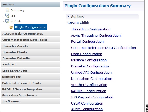
Select the Create Child action in a Plug-in Configuration node in the Systems tree to define them. You can change any of the variables from the default, or choose not to use a plug-in, as necessary.

When you create a system from the example, the following configuration stubs appear at the cluster and instance level:

Figure 1. Create Child Action

You are notified when a new policy is applied that overrides the existing configuration.

The notification is displayed as a warning icon above the configuration heading. When you hover over the warning icon, it displays the notification message as a tooltip. When there is an error and warning in the plugin configuration, then the error is overridden by a warning message.

A warning message is displayed under the following conditions:

  • At the System level, if the selected plugin configuration is overridden by cluster or Instance plugin configuration.

  • At the Cluster level, if the selected plugin configuration overrides the same plugin configuration at the system level or is overridden by the same plugin configuration at an Instance level.

  • At the Instance level, if the selected plugin configuration overrides the same plugin configuration at system or cluster level.

Threading Configuration

A threading configuration utility is provided for advanced users.

Click Threading Configuration in the right pane to add the threading configuration to the system. This is a performance tuning parameter and can be changed in case of a performance issue according to the call model and hardware. For further information, contact your Cisco Account representative.

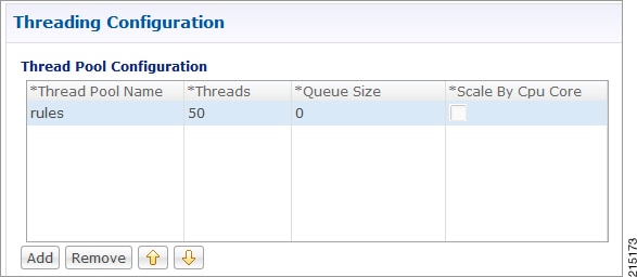
The Threading Plug-in is for Mobility. The only value to set is rules. It controls the total number of threads in the Policy Engine (QNS) that are executing at any given time. The default value is 50.

It is recommended not to configure the value below 50. It can be set higher to help increase performance in certain situations where the queue full issue or performance issue is being observed. The value also depends on call model, hardware type.

A configuration example is shown below:

Figure 2. Thread Pool Configuration

The following parameters can be configured under Threading Configuration:

Table 1. Threading Configuration Parameters

Parameter

Description

Thread Pool Name

Name of the Cisco thread pool i.e., rules.

Threads

Specify the threads to set in the thread pool. You can set rules thread ranging from 50 to 100 depending on the call flow (based on number of lookup operations).

  • rules = 50; Queue Size = 0; Scale By Cpu Core = unchecked

  • rules = 100; Queue Size = 0 (If TPS is > 2000 per Policy Server (QNS) depending on call model used; Scale By Cpu core = unchecked

The threads are driven based upon average response time of the message. The response time is call model dependent.

Queue Size

Specify the size of the queue before the threads are rejected.

If value is greater than 50, performance may degrade because it holds the number of tasks in queue waiting for threads to be executed when TPS is high.

If the value is lower than 50, the requests start dropping when all worker threads are busy in executing actions.

The queue belongs to each Policy Server (QNS) process, and it holds incoming messages from Policy Directors (LB), but also internal events/messages (for example, an internal time change that triggers a policy evaluation).

This is a performance tuning parameter and can be changed in case of a performance issue according to the call model and hardware.

Default value is 0.

Note


In most of the setups, keep the queue size value default.

Scale By Cpu Core

Select this check box to enable the processor cores to scale the maximum number of threads.

By default, this check box is unchecked.

Diameter Configuration

The Diameter Configuration section allows for the configuration of the diameter plug-in. It is recommended to configure the diameter plug-in at system level.

In order to define a Diameter Configuration at system level, perform these steps:

  1. Login into Policy Builder.

  2. Select Reference Data tab.

  3. From the left pane, select Systems.

  4. Select and expand your system name.

  5. Select Plugin Configurations.

  6. Select Diameter Configuration.

At Cluster Level

In order to define a Diameter Configuration at cluster level perform these steps:

  1. Log in into Policy Builder.

  2. Select Reference Data tab.

  3. From the left pane, select Systems.

  4. Select and expand your system name.

  5. Select and expand your cluster name. If no cluster has been created, create one by selecting the Cluster action.

  6. Select Plugin Configurations.

  7. Select Diameter Configuration.

These parameters can be configured under Diameter Configuration.

Table 2. Diameter Configuration Parameters

Parameter

Description

Default Gx Stale Session Timer Minutes

This timer is armed every time a message is received or sent for any given Gx session. When the timer expires (or more precisely within the next minute after the timer expires) a Gx RAR having the Re-Auth-Request-Type AVP set to AUTHORIZE_ONLY (0) message is triggered for that Gx session. If a Gx RAA is received having Result-Code AVP value set to DIAMETER_UNKNOWN_SESSION_ID (5002) or DIAMETER_UNABLE_TO_COMPLY (5012) the Gx session is deemed as stale and removed from the PCRF internal database. On any activity over Gx interface (RAR/CCR) the timer is reset.

Default value is 180 minutes.

Note

 
  • This timer unit is minute.

  • Stale Gx session removal triggers the PCRF session termination procedure for any other diameter sessions that were bound to the Gx session.

Use V9 Event Trigger Mapping

This option allows for a different set of list of valid values and their interpretation to be used for the Event-Trigger enumerated AVP in order to accommodate the change that occurred in the Gx specification between 3GPP TS 29.212 v9.5 (and prior) and 3GPP TS 29.212 v9.7 (and following including v10 v11 and v12). Default value is checked.

Note

 
  • The Event-Trigger AVP list of valid values and their interpretation defined in 3GPP TS 29.212 v9.6 is not supported.

  • Use V9 Event Trigger Mapping checked uses 3GPP TS 29.212 v9.5 as a reference while 3GPP TS 29.212 v110.10 is used as a reference when not checked.

Rel8 Usage Monitoring Supported

This option allows for the Gx usage monitoring feature to be supported even when the PCEF advertises support for Rel8 feature under Supported-Features AVP in Gx CCR-i.

Default value is checked.

Rel15 Ext Bw Nr Supported

When checked, it enables the support for 3GPP Rel-15 Extended BW-NR feature. PCRF sends response to AF/PCEF with Rel-15 Extended BW-NR feature bit set when the feature is enabled and AF/PCEF has also set the bit in the request message. PCRF sends extended QoS AVPs only if the configuration is enabled.

When unchecked, it disabled the support for 3GPP Rel-15 Extended BW-NR feature.

Default value is unchecked (disabled).

Stale Session Configuration

When a new row is added in “Stale Session Configuration” table the default value for the GX_TGPP SD_V11 and SY_V11 Stale session timer is 180 minutes.

Note


The maximum value allowed for the Stale Session Timer parameter is 35000 minutes.

If GX_TGPP Stale Session Timer value is not configured in this table, then the value is selected from the retained/old variable “Default Gx Stale Session Timer Minutes”.

If there are multiple values configured against any interface then the lowest among all would be considered as the stale session timer.

DRMP Prioritization

When enabled allows you to configure different message processing priorities based on the DRMP value received in the incoming request.

  • Default Inbound Priority - The default inbound priority value.

  • Inbound DRMP Prioritization

    • DRMP - DRMP AVP value in the incoming request.

    • Priority - Priority value assigned to the incoming message. Based on this value the message processing is prioritized. Higher Priority messages are be processed first compared to lower priority messages.


Note


If Gx stale session timer is set for both “Default Gx Stale Session timer Minutes” and “Stale Session Configuration” then the value configured Under “Stale Session Configuration” would take the precedence.


Table 3. Use V9 Event Trigger Mapping Valid Values

Interpretation - Use V9 Event Trigger Mapping is checked

Value

Interpretation - Use V9 Event Trigger Mapping is not checked

SGSN_CHANGE

0

SGSN_CHANGE

QOS_CHANGE

1

QOS_CHANGE

RAT_CHANGE

2

RAT_CHANGE

TFT_CHANGE

3

TFT_CHANGE

PLMN_CHANGE

4

PLMN_CHANGE

LOSS_OF_BEARER

5

LOSS_OF_BEARER

RECOVERY_OF_BEARER

6

RECOVERY_OF_BEARER

IP_CAN_CHANGE

7

IP_CAN_CHANGE

QOS_CHANGE_EXCEEDING

_AUTHORIZATION

11

QOS_CHANGE_EXCEEDING

_AUTHORIZATION

RAI_CHANGE

12

RAI_CHANGE

USER_LOCATION_CHANGE

13

USER_LOCATION_CHANGE

NO_EVENT_TRIGGERS

14

NO_EVENT_TRIGGERS

OUT_OF_CREDIT

15

OUT_OF_CREDIT

REALLOCATION_OF_CREDIT

16

REALLOCATION_OF_CREDIT

REVALIDATION_TIMEOUT

17

REVALIDATION_TIMEOUT

UE_IP_ADDRESS_ALLOCATE

18

UE_IP_ADDRESS_ALLOCATE

UE_IP_ADDRESS_RELEASE

19

UE_IP_ADDRESS_RELEASE

DEFAULT_EPS_BEARER

_QOS_CHANGE

20

DEFAULT_EPS_BEARER

_QOS_CHANGE

AN_GW_CHANGE

21

AN_GW_CHANGE

SUCCESSFUL_RESOURCE

_ALLOCATION

22

SUCCESSFUL_RESOURCE

_ALLOCATION

RESOURCE_MODIFICATION

_REQUEST

23

RESOURCE_MODIFICATION

_REQUEST

PGW_TRACE_CONTROL

24

PGW_TRACE_CONTROL

UE_TIME_ZONE_CHANGE

25

UE_TIME_ZONE_CHANGE

USAGE_REPORT

26

TAI_CHANGE

TAI_CHANGE

27

ECGI_CHANGE

ECGI_CHANGE

28

CHARGING_CORRELATION

_EXCHANGE

CHARGING_CORRELATION

_EXCHANGE

29

APN_AMBR_MODIFICATION

_FAILURE

USER_CSG_INFORMATION

_CHANGE

30

USER_CSG_INFORMATION

_CHANGE

DEFAULT_EPS_BEARER

_QOS_MODIFICATION_FAILURE

31

NA

NA

33

USAGE_REPORT

34

DEFAULT_EPS_BEARER

_QOS_MODIFICATION_FAILURE

35

USER_CSG_HYBRID

_SUBSCRIBED_INFORMATION

_CHANGE

36

USER_CSG_HYBRID

_UNSUBSCRIBED

_INFORMATION_CHANGE

37

ROUTING_RULE_CHANGE

39

APPLICATION_START

40

APPLICATION_STOP

42

CS_TO_PS_HANDOVER

43

UE_LOCAL_IP_

ADDRESS_CHANGE

44

HENB_LOCAL_IP_

ADDRESS_CHANGE

45

ACCESS_NETWORK_

INFO_REPORT

Next Hop routing

While selecting the peer that is used to deliver the request (with or without using the Next Hop Routes table) load balancing across the peers having the same rating is done. Load balancing starts from the peers having highest rating and covers all the peers in a round robin manner. If none is UP load balancing is tried with the peers having the second highest rating and again covers all the peers in a round robin manner and so on.


Note


Next Hop Routes table is used only for PCRF initiated requests. The response messages for any incoming request is always delivered on the same connection where the request was received or not delivered at all. This is in order to avoid asymmetric routes.


The DRA should explicitly advertise support for a Diameter application other than Relay. The Relay application having Application Identifier 0xffffffff is not supported.

These parameters can be configured under Next Hop routing table:

Table 4. Next Hop Routing Parameters

Parameter

Description

Next Hop Realm

DRA realm name as received in Origin-Realm AVP in CER or CEA message.

Note


All the next hop realms (Next Hop Realm) should match the Origin-Realm AVP value in the incoming CER/CEA message.

Next Hop Hosts

DRA hosts name list as received in Origin-Host AVP in CER or CEA message.

Note


All the next hop host names (Next Hop Hosts) should match the Origin-Host AVP value value in the incoming CER/CEA message.

Application Id

Diameter application id advertised as being supported by the DRA. It contains information that identifies the particular service that the service session belongs to.

Destination Realms Pattern

Actual destination realm name pattern as received in Origin-Realm AVP in AAR message. The pattern needs to follow the standard Java regular expression syntax described here.

Destination Host Pattern

Actual destination host name pattern as received in Origin-Host AVP in AAR message. The pattern needs to follow standard Java pattern conventions. The pattern needs to follow the standard Java regular expression syntax described here.

While populating the Next Hop Routes table, we recommend that you create only one entry for each Next Hop Realm value - Application Id value pair while all the DRA host names are provided as a list under Next Hop Hosts field. This is not a requirement though.


Note


The order in which the DRA hosts are provisioned in the Next Hop Hosts field for any given next hop route is not relevant. The DRA host having the highest rating (priority) value is used. In case multiple hosts have the same rating one is randomly selected. Outbound realm rating of next hop is not considered except for SY_PRIME.


CPC supports grouping of realms and application identifiers using wildcarding and assigns it to a group of next hop peers. CPC routes outgoing messages by selecting the peer with highest priority.

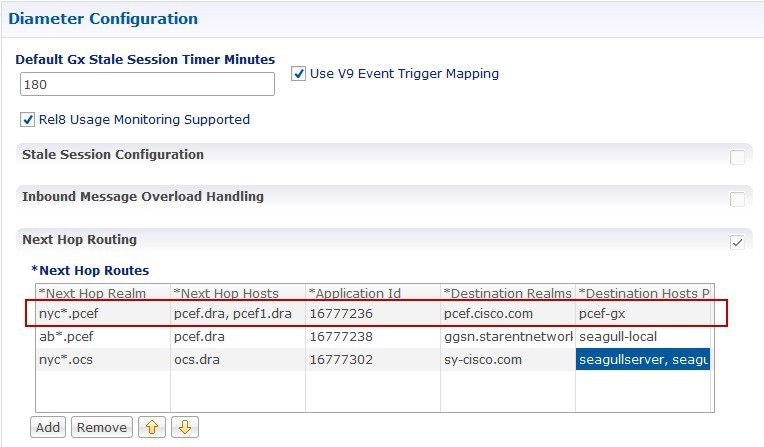
An example configuration for Grouping and Wildcarding in the Next Hop Routing table is shown below:

Figure 3. Grouping and Wildcarding in the Next Hop Routing Table

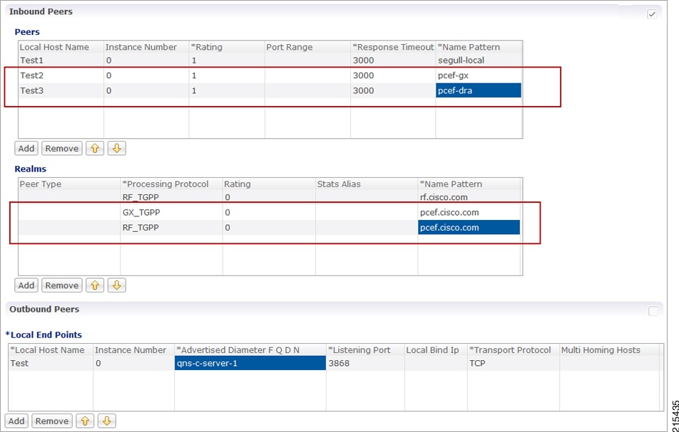
Destination Realm and Destination Hosts are used to map with the Peer configuration as defined in the Diameter Stack. The figure given below shows the mapping of the message containing the Realm from a peer to a protocol or interface.

Figure 4. Rating

Diameter Stack Configuration

You can enable the Diameter endpoint to dynamically create pods on a designated node or host. This feature might be a requirement when you want to ensure that the nodes are meeting specific security and regulatory parameters, or the node is closer to the data-center in terms of geographical proximity. The node affinity determines the node where CPC creates the Diameter endpoint pods, which are based on the affinity towards a node or group of nodes. Node affinity is a set of rules that allows you to define the custom labels on nodes and specify the label selectors within the pods. Based on these rules, the scheduler determines the location where the pod can be placed.


Note


If you do not specify a node, then the Kubernetes scheduler determines the node where the Diameter endpoint creates a pod.


CPC supports both IPv4 and IPv6 connectivity on its external interfaces/endpoints (inbound and outbound).

Configuring the Node for the Diameter Endpoint Pod

This section describes how to specify the node or host where the Diameter endpoint must spawn the pod.


Note


Configuration changes to the diameter endpoint cause the endpoint to restart automatically. Cisco recommends making such changes only within the maintenance window.


To specify the node where you want Diameter endpoint to spawn the pod, use this configuration:

config 
   diameter group diameter_group_name 
   mode server server_name 
   stack stack_name 
     application application_name 
     bind-ip ipv4 host_address 
     bind-ipv6 ipv6 host_address 
     bind-port port_number 
     fqdn fqdn_address 
     realm realm_address 
     node-host node_host_address 
     end 

Note


  • diameter group diameter_group_name —Specify the Diameter group name.

  • mode server server_name —Specify the server name that operates as the mode server.

  • stack stack_name —Specify the stack name.

  • application application_name —Specify the application name.

  • bind-ip host_address —Specify the host address IPv4 to bind the stack.

  • bind-ipv6 host_address —Specify the host address IPv6 to bind the stack.

  • bind-port port_number —Specify the port number to bind the stack.

  • fqdn fqdn_address —Specify the FQDN address.

  • realm realm_address —Specify the realm address.

  • node-host node_host_address —Specify the host IP address of the node.


Sample Configuration

This is a sample configuration of the node configuration.

mode server 
  stack cicdsite 
  application rx 
  bind-ip 192.0.2.18 
  realm cisco.com 
  node-host for-node-2a-worker39e1587354h 
  exit 

Settings

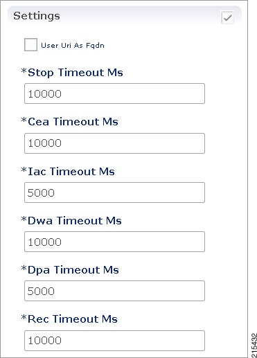
You can provision different timers that are available at the diameter stack level.

Figure 5. Settings


These parameters can be configured under Settings:

Table 5. Settings Parameters

Parameter

Description

User Uri As Fqdn

Sets the Origin-Host AVP value in CER/CEA to the user URI value instead of FQDn value.

Default value is not set.

Stop Timeout Ms

Sets the timeout duration for a stack to wait till all the resources stop. The delay is in milliseconds.

Default value is 10000.

Cea Timeout Ms

Sets the CER or CEA exchange timeout duration in case of no response. The delay is in milliseconds.

Default value is 10000.

Iac Timeout Ms

Sets the timeout duration for a waiting stack before retrying the communication with a peer that has stopped answering DWR messages. The delay is in milliseconds.

Default value is 5000.

Dwa Timeout Ms

Sets the DWR or DWA exchange timeout duration in case of no response. The delay is in milliseconds.

Default value is 10000.

Dpa Timeout Ms

Sets the DPR or DPA exchange timeout duration in case of no response. The delay is in milliseconds.

Default value is 5000.

Rec Timeout Ms

Sets the timeout duration for reconnection procedure. The delay is in milliseconds.

Default value is 10000.

Dynamic ARP Functionality for PC and PV

CPC supports the dynamic ARP feature to send the same Priority-Level value in the dedicated bearers as that of the default bearer.

The dynamic ARP functionality is extended to Preemption Capability (PC) and Preemption Vulnerability (PV).

The PC parameter defines whether a bearer with a lower priority level can be dropped to free up the required resources.

The PV parameter defines whether a bearer is applicable for such dropping by a preemption capable bearer with a higher priority value.

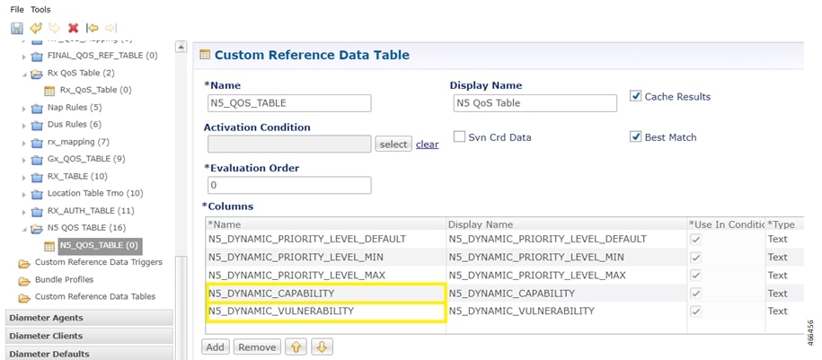
To support this functionality for Rx interface, add two new columns, Rx_Dynamic_Vulnerability and Rx_Dynamic_Capability to the Rx_QoS_Table and for N5 interface, add two new columns, N5_Dynamic_Vulnerability and N5_Dynamic_Capability to the N5_QoS_Table.

How Dynamic ARP Works

This section describes how this feature works.

For a WPS user, the default bearer ARP value includes a Priority-Level value with PC set to enabled and PV set to disabled.

In case, when a non-WPS user calls a WPS user in Rx interface, the dynamic ARP attribute in the Rx_QoS_Table initiates the CPC to set the Priority-Level value in the dedicated bearer rules to match that of the default bearer value. But the PVI/PCI values sent in the dedicated bearer rules use the enforced values from the Rx_QoS_Table (typically PVI enabled, PCI disabled).

In case, when a non-WPS user calls a WPS user in N5 interface, the dynamic ARP attribute in the N5_QoS_Table initiates the CPC to set the Priority-Level value in the dedicated bearer rules to match that of the default bearer value. But the PVI/PCI values sent in the dedicated bearer rules use the enforced values from the N5_QoS_Table (typically PVI enabled, PCI disabled).

For WPS user, if dynamic ARP attribute for PVI and PCI is set to "D", then the PVI and PCI values will be mirrored from the default bearer instead using the configured Rx QoS Table values in Rx interface and configured N5 QoS Table values in N5 interface.

Configure CRD table and RxSTG configuration AVP

Configuring CRD table and RxSTG configuration AVP involves these steps:

Adding Rx Dynamic capability and Rx Dynamic vulnerability

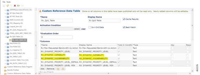
To add Rx_Dynamic_Capability and Rx_Dynamic_Vulnerability columns to the Rx_QoS CRD table, use these steps:

  1. Log in to Policy Builder.

  2. Click the Reference Data tab, and from the left pane click Custom Reference Data Tables to view the options.

  3. On the left pane, expand the Search Table Groups folder.

  4. Expand the Rx_QoS_Table sub folder of Search Table Groups and click the.Rx_QoS_Table

  5. Go to the *Columns field and click the Add.

  6. Add the column Name and Display Name as RX_DYNAMIC_CAPABILITY and RX_DYNAMIC_VULNERABILITY.

Figure 6. Adding Rx_Dynamic_Capability and Rx_Dynamic_Vulnerability

Configuring RxSTGConfiguration AVP

This section describes the parameters that can be configured for RxSTGConfiguration.

The RxSTGConfiguration service configuration supports the following output AVPs that allow the dynamic value expression.

Before setting the service parameters, ensure that you create a use case template and add a service for this configuration.

The following table describes the RxSTGConfiguration service parameter.

Table 6. RxSTGConfiguration ParameterD
Parameters Description

Dynamic-QoS-ARP-Pre-Emption-Capability

If the value is configured as "D" then the feature is enabled for PC. If the value is configured with any other value except "D" or is empty then the feature is disabled for PC.

Dynamic-QoS-ARP-Pre-Emption-Vulnerability

If the value is configured as "D" then the feature is enabled for PV. If the value is configured with any other value except "D" or is empty then the feature is disabled for PV.

Configuring CRD Table and N5STGConfiguration AVP

Configuring CRD table and N5STGConfiguration AVP involves these steps:

Adding N5_Dynamic_Capability and N5_Dynamic_Vulnerability

To add N5_Dynamic_Capability and N5_Dynamic_Vulnerability columns to the N5_QoS CRD table, use these steps:

  1. Log in to Policy Builder.

  2. Click the Reference Data tab, and from the left pane click Custom Reference Data Tables to view the options.

  3. On the left pane, expand the Search Table Groups folder.

  4. Expand the N5_QoS_Table sub folder of Search Table Groups and click the N5_QoS_Table.

  5. Go to the *Columns field and click the Add.

  6. Add the column Name and Display Name as N5_DYNAMIC_CAPABILITY and N5_DYNAMIC_VULNERABILITY.

Figure 7. Adding N5_Dynamic_Capability and N5_Dynamic_Vulnerability

Configuring N5STGConfiguration AVP

This section describes the parameters that can be configured for N5STGConfiguration.

The N5STGConfiguration service configuration supports the following output AVPs that allow the dynamic value expression.

Before setting the service parameters, ensure that you create a use case template and add a service for this configuration.

The following table describes the N5STGConfiguration service parameter.

Table 7. N5STGConfiguration ParameterD
Parameters Description

Dynamic-QoS-ARP-Pre-Emption-Capability

If the value is configured as "D" then the feature is enabled for PC. If the value is configured with any other value except "D" or is empty then the feature is disabled for PC.

Dynamic-QoS-ARP-Pre-Emption-Vulnerability

If the value is configured as "D" then the feature is enabled for PV. If the value is configured with any other value except "D" or is empty then the feature is disabled for PV.

OAM Support

This section describes operations, administration, and maintenance support for this feature

Bulk Statistics Support

These statistics are supported for the dynamic ARP functionality for PC and PV feature.


Note


These values apply to all the statistics:

  • Unit - Int64

  • Type - Counter

  • Nodes - Service


  • qos_rule_pc_total - Indicates the number of N5/N7/Rx rule installs (per qci/Media Type) provisioned with dynamic QoS PCI.

    The following labels are defined for this metric:

    • Interface

      • N5

      • N7

      • Rx

    • type

      • default_qos_pc

      • dynamic_qos_pc

    • identifier

      • qci

      • media-type

    • arp_pc

  • qos_rule_pv_total - Indicates the number of N5/N7/Rx rule installs (per qci/Media Type) provisioned with dynamic QoS PVI.

    These labels are defined for this metric:

    • Interface

      • N5

      • N7

      • Rx

    • type

      • default_qos_pv

      • dynamic_qos_pv

    • identifier

      • qci

      • media-type

    • arp_pv

Modified Stats

Table 8. Modified Stats

Old Stats

New Stats

Description

qos_rule_total

qos_rule_pl_total

Indicates the number of N5/N7/Rx rule installs (per qci/Media Type) provisioned with dynamic QoS PL.

These labels are defined for this metric:

  • Interface

    • N5

    • N7

    • Rx

  • type

    • default_qos_pl

    • dynamic_qos_pl

  • identifier

    • qci

    • media-type

  • arp_pl

Feature Description

CPC supports Diameter application KPI’s and Alerts support in parity with PCRF application.

How It Works

This section describes how this feature works.

Statistics

node[x].messages.e2e __[realm_] Gx_CCR-I_2001. qns_stat.success

Description: Success message Policy Director count for return code 2001

node[x].messages.e2e __[realm_] Gx_CCR-I_2001. qns_stat.total _time_in_ms

Description: Total milliseconds Policy Director of successful messages with return code matching 2001

node[x].messages.e2e __[realm_] Gx_CCR-I_3xxx. qns_stat.success

Description: Success count of Policy Director messages with return code matching 3XXX

node[x].messages. e2e__ [realm_] Gx_CCR-I_4xxx. qns_stat.success

Description: Success count of Policy Director messages with return code matching 4XXX

node[x].messages. e2e__ [realm_] Gx_CCR-I_5xxx. qns_stat.success

Description: Success count of Policy Director messages with return code matching 5XXX

node1.counters. [realm_] Gx_CCR-I.qns_count

Description: Count of messages Policy Server (qns) successful sent to the policy engine

node[x].messages. e2e__ [realm_] Gx_CCR-U_2001. qns_stat.success

Description: Success message count for return code 2001

node[x].messages. e2e__ [realm_] Gx_CCR-U_2001. qns_stat.total_ time_in_ms

Description: Total milliseconds of successful messages with return code matching 2001

node[x].messages. e2e__ [realm_] Gx_CCR-U_3xxx. qns_stat.success

Description: Success count of messages with return code matching 3XXX

node[x].messages. e2e__ [realm_] Gx_CCR-U_4xxx. qns_stat.success

Description: Success count of messages with return code matching 4XXX

node[x].messages. e2e__ [realm_] Gx_CCR-U_5xxx. qns_stat.success

Description: Success count of messages with return code matching 5XXX

node1.counters. [realm_] Gx_CCR-U. qns_count

Description: Count of messages Policy Server (qns) successful sent to the policy engine

node[x].messages. e2e__ [realm_] Gx_CCR-U_2001. qns_stat.success

Description: Success message count for return code 2001

node[x].messages. e2e__ [realm_] Gx_CCR-U_2001. qns_stat. total_time_in_ms

Description: Total milliseconds of successful messages with return code matching 2001

node[x].messages. e2e__ [realm_] Gx_CCR-U_3xxx. qns_stat.success

Description: Success count of messages with return code matching 3XXX

node[x].messages. e2e__ [realm_] Gx_CCR-U_4xxx. qns_stat.success

Description: Success count of messages with return code matching 4XXX

node[x].messages. e2e__ [realm_] Gx_CCR-U_5xxx. qns_stat.success

Description: Success count of messages with return code matching 5XXX

node1.counters. [realm_] Gx_CCR-U. qns_count

Description: Count of messages successful sent to the policy engine

node1.counters. [realm_] Gx_CCR-T. qns_count

Description: Success message count for return code 2001

node[x].messages. e2e__ [realm_] Gx_CCR-T_2001. qns_stat.success

Description: Total milliseconds of successful messages with return code matching 2001

node[x].messages.e2e_<domain>_[realm_]Gx_CCR-T_3xxx.qns_stat.success

Description: Success count of messages with return code matching 3XXX

node[x].messages. e2e__ [realm_] Gx_CCR-T_4xxx. qns_stat.success

Description: Success count of messages with return code matching 4XXX

node[x].messages. e2e__ [realm_] Gx_CCR-T_5xxx. qns_stat.success

Description: Success count of messages with return code matching 5XXX

node1.counters. [realm_] Gx_CCR-T.qns_count

Description: Count of messages successful sent to the policy engine

node1.counters. [realm_] Gx_RAR-T. qns_count

Description: Success message count for return code 2001

node[x].messages. e2e__ [realm_] Gx_RAR-T_2001. qns_stat.success

Description: Total milliseconds of successful messages with return code matching 2001

node[x].messages.e2e_<domain>_[realm_]Gx_RAR-T_3xxx.qns_stat.success

Description: Success count of messages with return code matching 3XXX

node[x].messages. e2e__ [realm_] Gx_RAR-T_4xxx. qns_stat.success

Description: Success count of messages with return code matching 4XXX

node[x].messages. e2e__ [realm_] Gx_RAR-T_5xxx. qns_stat.success

Description: Success count of messages with return code matching 5XXX

node[x].messages. e2e__ [realm_] Gx_RAR_timeout. qns_stat.success

Description: Success timeout Policy Director count for RAR message

node1.counters. [realm_] Gx_RAA.qns_count

Description: Count of all messages sent to the policy engine

node1.messages. in_q_Gx_RAA. qns_stat.error

Description: Count of messages failed to be sent to the policy engine

node1.messages. in_q_Gx_RAA. qns_stat.success

Description: Count of messages successful sent to the policy engine

node1.counters. [realm_] Gx_RAR.qns_count

Description: Count of messages successful sent to the Policy Director (LB)

node[x].messages. e2e__ [realm_] Rx_AAR_2001. qns_stat.success

Description: Success message count for return code 2001

node[x].messages. e2e__ [realm_] Rx_AAR_2001. qns_stat.total_ time_in_ms

Description: Total milliseconds of successful messages with return code matching 2001

node[x].messages. e2e__ [realm_] Rx_AAR_3xxx. qns_stat.success

Description: Success count of Policy Director messages with return code matching 3XXX

node[x].messages. e2e__ [realm_] Rx_AAR_4xxx. qns_stat.success

Description: Success count of Policy Director messages with return code matching 4XXX

node[x].messages. e2e__ [realm_] Rx_AAR_5xxx. qns_stat.success

Description: Success count of Policy Director messages with return code matching 5XXX

node1.counters. [realm_] Rx_RAA.qns_count

Description: Count of messages successful sent to the Policy Director (LB)

node1.counters. [realm_] Rx_AAR_drop. qns_count

Description: Count of messages dropped due to exceeding SLA

node1.counters. [realm_] Rx_AAA_2001. qns_count

Description: Count of AAA messages with result-code = 2001 sent successfully to the Policy Director (LB)

node[x].messages. e2e__ [realm_] Rx_ASR_2001. qns_stat.success

Description: Success message count for return code 2001

node[x].messages. e2e__ [realm_] Rx_ASR_2001. qns_stat.total_ time_in_ms

Description: Total milliseconds of successful messages with return code matching 2001

node[x].messages. e2e__ [realm_] Rx_ASR_3xxx. qns_stat.success

Description: Success count of Policy Director messages with return code matching 3XXX

node[x].messages. e2e__ [realm_] Rx_ASR_5xxx. qns_stat.success

Description: Success count of Policy Director messages with return code matching 5XXX

node1.counters. [realm_] Rx_ASA_bypass. qns_count

Description: Count of message that do not require processing by the policy engine

node1.counters. [realm_]Rx_ASA. qns_count

Description: Count of messages successful sent to the policy engine

node1.counters. [realm_] Rx_ASA_drop. qns_count

Description: Count of messages dropped due to exceeding SLA

node[x].messages. e2e__ [realm_] Rx_RAR_2001. qns_stat.success

Description: Success message count for return code 2001

node[x].messages. e2e__ [realm_] Rx_RAR_2001. qns_stat.total_ time_in_ms

Description: Total milliseconds of successful messages with return code matching 2001

node[x].messages. e2e_<domain>_[realm_] Gx_RAR-T_3xxx. qns_stat.success

Description: Success count of messages with return code matching 3XXX

node[x].messages. e2e__ [realm_] Gx_RAR-T_4xxx. qns_stat.success

Description: Success count of messages with return code matching 4XXX

node[x].messages. e2e__ [realm_] Gx_RAR-T_5xxx. qns_stat.success

Description: Success count of messages with return code matching 5XXX

node1.counters. [realm_] Rx_RAA_bypass. qns_count

Description: Count of messagethat do not require processing by the policy engine

node1.counters. [realm_] Rx_RAA.qns_count

Description: Count of message successful sent to the policy engine

node1.counters. [realm_] Rx_RAA_drop. qns_count

Description: Count of messages dropped due to exceeding SLA

node[x].messages. e2e__ [realm_] Rx_STR_2001. qns_stat.success

Description: Success message count for return code 2001

node[x].messages. e2e__ [realm_] Rx_STR_2001. qns_stat.total_time_in_m

Description: Total milliseconds of successful messages with return code matching 2001

node[x].messages. e2e__ [realm_] Rx_STR_3xxx. qns_stat.success

Description: Success count of messages with return code matching 3XXX

node[x].messages. e2e__ [realm_] Rx_STR_4xxx. qns_stat.success

Description: Success count of messages with return code matching 4XXX

node[x].messages. e2e__ [realm_] Rx_STR_5xxx. qns_stat.success

Description: Success count of messages with return code matching 5XXX

node1.counters. [realm_] Rx_STR.qns_count

Description: "Count of messages successful sent to the policy engine"

node1.counters. [realm_] Rx_STR_drop. qns_count

Description: Count of messages dropped due to exceeding SLA

node1.messages. in_q_Rx_STR. qns_stat.success

Description: "Count of messages successful sent to the policy engine"

node1.messages. in_q_Rx_STR. qns_stat. total_time_in_ms

Description: Total milliseconds of messages successfully sent to the policy engine

node1.messages. diameter_Rx_STR. qns_stat.success

Description: Success message count

node1.messages. diameter_Rx_STR. qns_stat. total_time_in_ms

Description: Total milliseconds of successful messages

node1.counters. [realm_] Rx_STA_2001. qns_count

Description: Count of STA messages with result-code = 2001 sent successfully to the Policy Director (LB)
Alarms

RxAAR

Description: "This alert is fired when the percentage of Success Rx AAR responses send is lesser threshold."

Formula:

sum(increase(diameter_responses_total{command_code=\”AAA\”,response_status=~\”2001\”}[5m])) / sum(diameter_responses_total(outgoing_request_total{command_code=\”AAA\”}[5m])) < 0.90”

RxSTA

Description: "This alert is fired when the percentage of Success Rx STA responses send is lesser threshold."

Formula:

sum(increase(diameter_responses_total{command_code=\”STA\”,response_status=~\”2001\”}[5m])) /sum(diameter_responses_total(outgoing_request_total{command_code=\”STA\”}[5m])) < 0.90

RxRAR

Description: "This alert is fired when the percentage of Success Rx RAR responses Received is lesser threshold."

Formula:

sum(increase(diameter_responses_total{command_code=\”RAA\”, response_status=~\”2001\”}[5m]))/sum(diameter_responses_total(outgoing_request_total{command_code=\”RAA\”}[5m])) < 0.90

RxASR

Description: "This alert is fired when the percentage of Success Rx ASR responses send is lesser threshold."

Formula:

sum(increase(diameter_responses_total{command_code=\”ASA\”,response_status=~\”2001\”}[5m])) /sum(diameter_responses_total(outgoing_request_total{command_code=\”ASA\”}[5m])) < 0.90

pod-down

Description: CDL EP Pod Down

Formula:

up{pod=~'cdl-ep.*'} == 0

pod-down

Description: CDL Pod Slot Change

Formula:

up{pod=\"cdl-slot-session-c1-m1-0\"} == 0

pod-down

Description: Diameter EP Change

Formula:

up{pod=~'diameter-ep.*'} == 0

pod-down

Description: EP Mapping Change

Formula:

up{pod=~'etcd-pcf.*'} == 0

pod-down

Description: Grafana Dashboard Change

Formula:

up{pod=~'grafana-dashboard.*'} == 0

pod-down

Description: Kafka Changed

Formula:

up{pod=~'kafka.*'} == 0

pod-down

Description: LDAP Pod Changed

Formula:

up{pod=~'ldap-pcf.*'} == 0

pod-down

Description: CPC Engine Changed

Formula:

up{pod=~pcf-engine-pcf.*'} == 0

pod-down

Description: CPC Rest EP Change

Formula:

up{pod=~'pcf-rest-ep.*'} == 0

LDAP Query

Description: "This alert is fired when the success percentage of ldap query request is lesser threshold."

Formula:

sum(increase(message_total{type=~\”.*_ldap_query\”, status=\”success\”}[5m])) /sum(increase(message_total{type=~\”.*_ldap_query\”}[5m])) < 0.90

LDAP Modify

Description: "This alert is fired when the success percentage of ldap modify request is lesser threshold."

Formula:

sum(increase(message_total{component=\”ldap-ep\”, type=~\”.*_ldap_modify\”,status=\”success\”}[5m])) / sum(increase(message_total{component=\”ldap-ep\”,type=~\”.*_ldap_modify\”}[5m])) < 0.90

PLF Request

Description: This alert is fired when the success percentage of PLF request is lesser threshold.

Formula:

sum(increase(message_total{type=~\”ldap_search-res_success\”,status=\”success\”}[5m])) /sum(increase(message_total{type=~\”ldap_search-res_.*\”}[5m])) <0.90

NAP Notification

Description: This alert is fired when the success percentage of NAP request is lesser threshold.

Formula:

sum(increase(message_total{type=~\”ldap_change-res_success\”, status=\”success\”}[5m])) /sum(increase(message_total{type=~\”ldap_change-res_.*\”}[5m])) <0.90

node-disk-running-full

Description: test

Formula:

node_filesystem_usage > 0.0001

vm-down

Description: VM Down

Formula:

up{pod=~\"node-expo.*\"} == 0

mem-util-high

Description: High Memory Usage

Formula:

avg(node_memory_MemAvailable_bytes /node_memory_MemTotal_bytes * 100) by (hostname) < 20

disk-util-high

Description: High Disk Usage

Formula:

avg (node_filesystem_avail_bytes{mountpoint =\"/\"} /node_filesystem_size_bytes{mountpoint =\"/\"} *100) by (hostname) <20

cpu-util-idle

Description: High CPU Usage

Formula:

avg(rate(node_cpu_seconds_total{mode='idle'}[1m])) by (hostname) *100 < 50

Implementation of SPR MongoDB in CPC

The CPC supports efficient subscriber authorization for Gx and N7 interfaces through integration with SPR. This integration enables the CPC to provide internal access to the SPR and the Unified API Endpoint, facilitating seamless policy management and updates.

The key aspects include:

  • Subscriber Session Policy Review:

    Upon receiving notifications of any changes in subscriber profiles stored in the SPR database, the CPC automatically reviews the associated subscriber session policies.

  • Policy Update Notifications:

    If a subscriber policy update is necessary following a profile change, the CPC initiates the appropriate actions by sending a Gx-Re-Authorization Request (Gx-RAR) or an N7 Notify message.

  • Seamless Integration with SMF:

    In the event of a policy change, the CPC uses the N7 Notify message to communicate with the Session Management Function (SMF), ensuring that all sessions are updated in accordance with the latest subscriber policies.

The SPR MongoDB Deployment in CPC for Subscriber Data Handling feature involves deploying MongoDB replica sets within the CPC Kubernetes cluster namespace. These replica sets are crucial for storing policy and charging control information of subscribers, which are provisioned through the CPC Unified API endpoint. The SPR deployed with Geo Redundancy - Multisite MongoDB Cluster with site local Unified API and API Router support.

In the case of Embedded Subscriber Profile Repository (SPR), CPC supports subscriber authorization for Gx and N7. The CPC provides internal access to both SPR and the Unified API Endpoint. The SPR databases get configured in an existing administration database replica set or used as a separate MongoDB replica set.

CPC must review the subscriber session policies if any subscriber profile changes get notified in the SPR DB. If there is any post profile update in the subscriber policy, the CPC sends a Gx-RAR or N7 Notify message. When the CPC receives the notification, it locates the subscriber profile from the SPR DB, reviews the policy, and initiates an N7 Notify message to SMF if there is any policy change.

Configure SPR Mongo Replica Sets in CPC

This procedure allows to configure SPR mongo replica sets in Ops-Center and in policy builder (PB) page.

Procedure


Step 1

Login to the Global Configuration mode.

config // Enter config mode

Step 2

Enter the given CLI command for CDL configuration to retrieve the N7 session which needs to be re-evaluated while there is a change in subscriber profile:

cdl datastore session
find-by-nuk-prefixes USuMMissingCredKey
exit
cdl datastore session
find-by-nuk-prefixes USuMSubscriberIdKey
exit

Step 3

Enter the CLI command for CPC engine configuration.

engine <ENGINE_NAME>
properties usum.missingcredential.keyname value USuMMissingCredKey
exit

Note

 
  • Add these configurations when all the pods are in shutdown state.

  • Here is the sample configuration of mongo replica set in Ops-Center:

    db scdb replica-name mongo-spr1
    	port 27018
    	interface db1.mdb.2564
    	resource memory limit 112000
    	replica-set-label key smi.cisco.com/node-type-5
    	replica-set-label value db-spr
    	member-configuration member sprdb-rs1-arbiter
    		host 10.160.158.195
    		arbiter true
    		site remote
    	exit
    	member-configuration member sprdb-rs1-s1-m1
    		host 10.160.9.196
    		arbiter false
    		priority 166
    		site remote
    	exit
    	member-configuration member sprdb-rs1-s1-m2
    		host 10.160.9.197
    		arbiter false
    		priority 155
    		site remote
    	exit
    	member-configuration member sprdb-rs1-s2-m1
    		host 10.160.49.196
    		arbiter false
    		priority 66
    		site local
    	exit
    	member-configuration member sprdb-rs1-s2-m2
    		host 10.160.49.197
    		arbiter false
    		priority 55
    		site local
    	exit
    exit
    db scdb replica-name mongo-spr2
    	port 27019
    	interface db1.mdb.2564
    	resource memory limit 112000
    	replica-set-label key smi.cisco.com/node-type-5
    	replica-set-label value db-spr
    	member-configuration member sprdb-rs2-arbiter
    		host 10.160.158.195
    		arbiter true
    		site remote
    	exit
    	member-configuration member sprdb-rs2-s1-m1
    		host 10.160.9.198
    		arbiter false
    		priority 166
    		site remote
    	exit
    	member-configuration member sprdb-rs2-s1-m2
    		host 10.160.9.199
    		arbiter false
    		priority 155
    		site remote
    	exit
    	member-configuration member sprdb-rs2-s2-m1
    		host 10.160.49.198
    		arbiter false
    		priority 66
    		site local
    	exit
    	member-configuration member sprdb-rs2-s2-m2
    		host 10.160.49.199
    		arbiter false
    		priority 55
    		site local
    	exit
    exit
    

Step 4

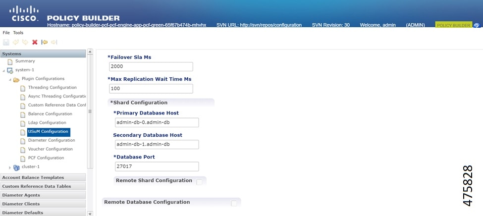
Login to policy builder page and select Plugin Configuration option. Click the USuM Configuration option.

Figure 8. USuM Configuration

Step 5

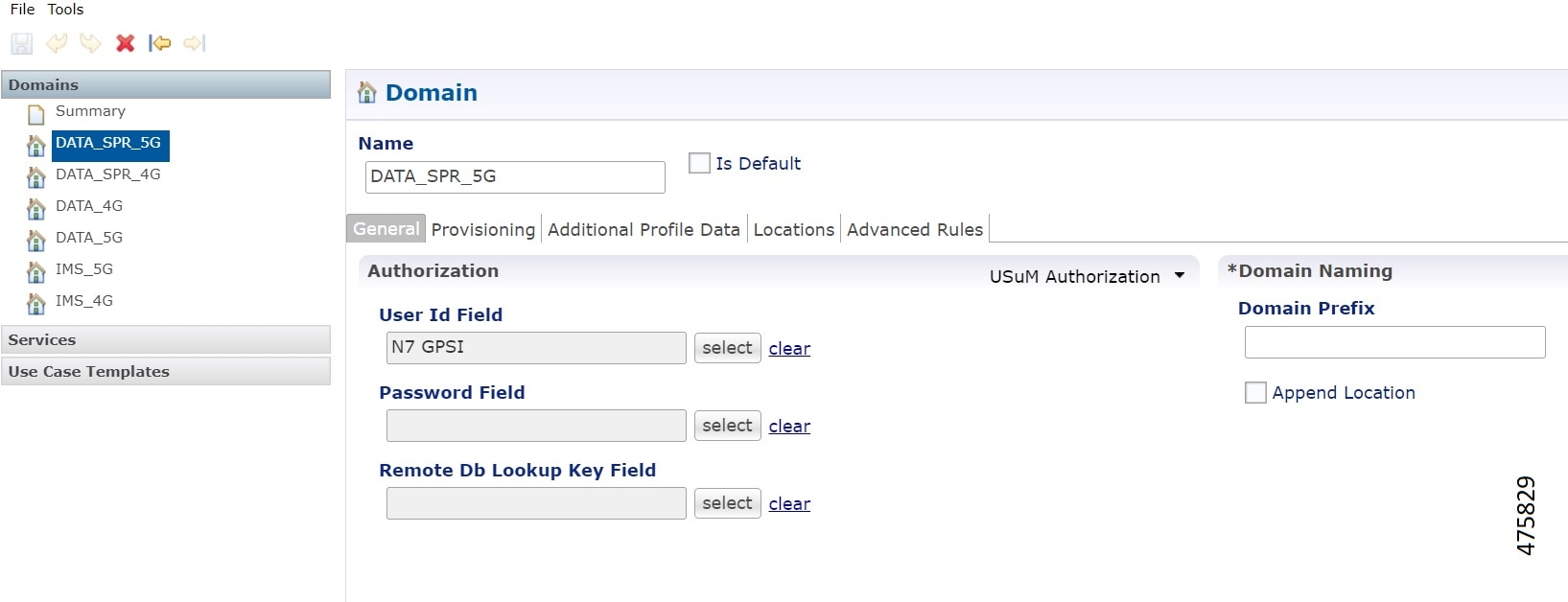
Use the N7 GPSI or SUPI value as a lookup key for N7 configuration in SPR.

Figure 9. SPR N7 Configuration

Step 6

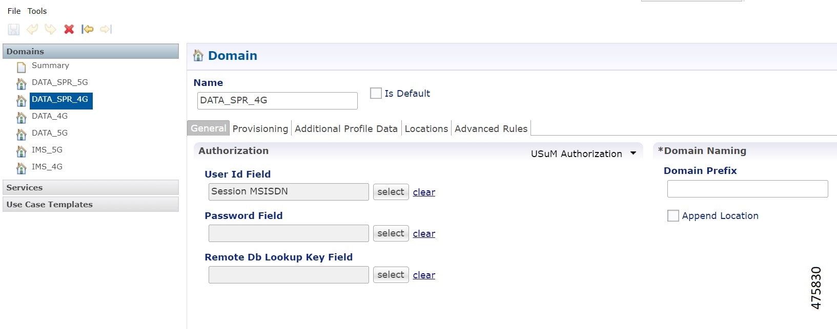
In the Domain tab, select the USuM Authorization option from drop down. You can use the Gx IMSI or MSISDN as a lookup key for Gx configuration.

Figure 10. SPR Gx Configuration

API Router Functionality for Subscriber Data Storage

The API Router functionality allows the CPC to store and manage subscriber data across multiple SPR replica sets. This is particularly useful for managing large volumes of subscriber data and ensuring high availability and redundancy. The feature also supports multi-credential management, enabling the system to handle subscribers with multiple identifiers.

Multi-Credential Management

The IMSI or MSISDN number of a subscriber is the primary networkId of a subscriber. CPC supports creation or modification action for subscribers using the IMSI and MSISDN numbers. The MSISDN and IMSI numbers can have the same or different ending starting from 0 through 4 or from 5 through 9.

Use these API queries to create or edit subscriber data:

  • CreateSubscriberRequest: Create a subscriber with both IMSI and MSISDN credentials

  • GetSubscriberRequest: Query a subscriber by either IMSI or MSISDN.


    Note


    To skip the error code when the subscriber is not available, set the uapi.get.sub.skip.fail.response CLI to true.


  • DeleteSubscriberRequest: Delete a subscriber by either IMSI or MSISDN.

  • ChangeCredentialUsernameRequest: Change the credential for a subscriber by either IMSI or MSISDN.

Here is an example for subscriber creation:

<CreateSubscriberRequest>
            <subscriber>
                    <credential>
                            <networkId>5678</networkId>
                            <type>IMSI</type>
                    </credential>
                    <credential>
                            <networkId>1234</networkId>
                            <type>primary</type>
                    </credential>
                    <credential>
                            <networkId>bob</networkId>
                    </credential>
                     ...
            </subscriber>
        </CreateSubscriberRequest>

Set Network ID in Domain Configuration

Use the MSISDN or IMSI number as a network ID of a subscriber to support multiple SPR.

Procedure

Step 1

Click the Services option on right side of Policy Builder page.

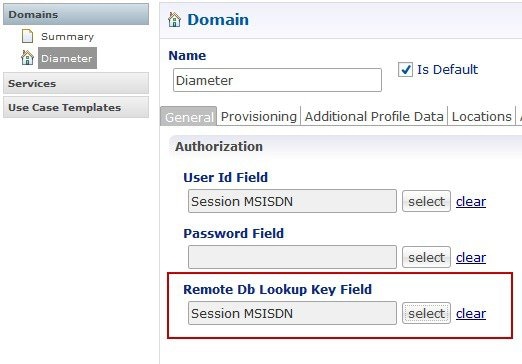
Step 2

In the Domain tab on right pane, select the Remote Db Lookup Key Field as Session MSISDN or Session IMSI option.


Configure API router to route subscriber data

Configure the API router to route the subscriber data based on the last digit of the networkId. Here, the SPR1 stores the subscriber information for networkId that ends with 0 through 4 and SPR2 stores the subscriber information for networkId that ends with 5 through 9.

Before you begin

To install the API router feature, configure the installation feature parameters in Ops Center. Login to the configuration mode and set the CLI configuration for engine:

engine <ENGINE_NAME> install-features policy-builder com.broadhop.client.feature.apirouter
engine <ENGINE_NAME> install-features policy-server com.broadhop.apirouter.service.feature 
Procedure

Step 1

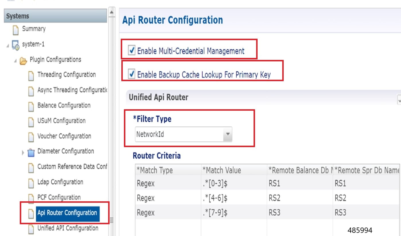
In the left pane of Policy Builder page, click Plugin Configurations option.

Step 2

Click the API Router Configuration tab.

Step 3

Select the Enable Multi-Credential Management check box.

Step 4

Select the Enable Backup Cache Lookup For Primary Key check box.

Step 5

Set the Filter Type as NetworkId to configure mutiple SPR. The Router Criteria displays remote SPR database values from USuM Configuration and Remote Balance Database from Balance Configuration .


Configure Remote Database with Balance Configuration

You can configure the remote balance database in Policy Builder page using Balance configuration tab.

Procedure

Step 1

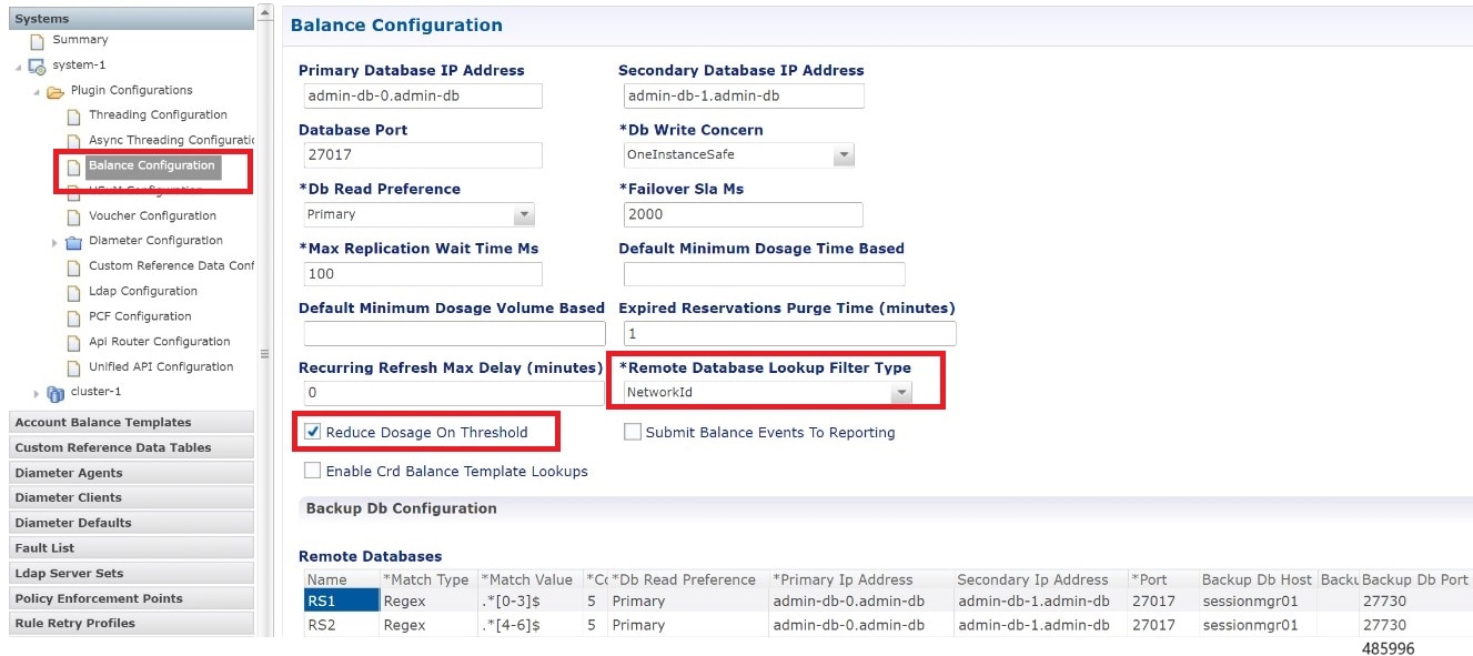
In the left pane of Policy Builder page, click Plugin Configurations option.

Step 2

Select Balance Configuration tab.

Step 3

Enter the mandatory values.

Step 4

By default, the Remote Database Lookup Filter Type is set as Networkid and the Reduce Dosage on Threshold check box is selected.


Configure Remote Database with USuM Configuration

You can configure the remote SPR database in Policy Builder page using UsuM configuration tab.

Procedure

Step 1

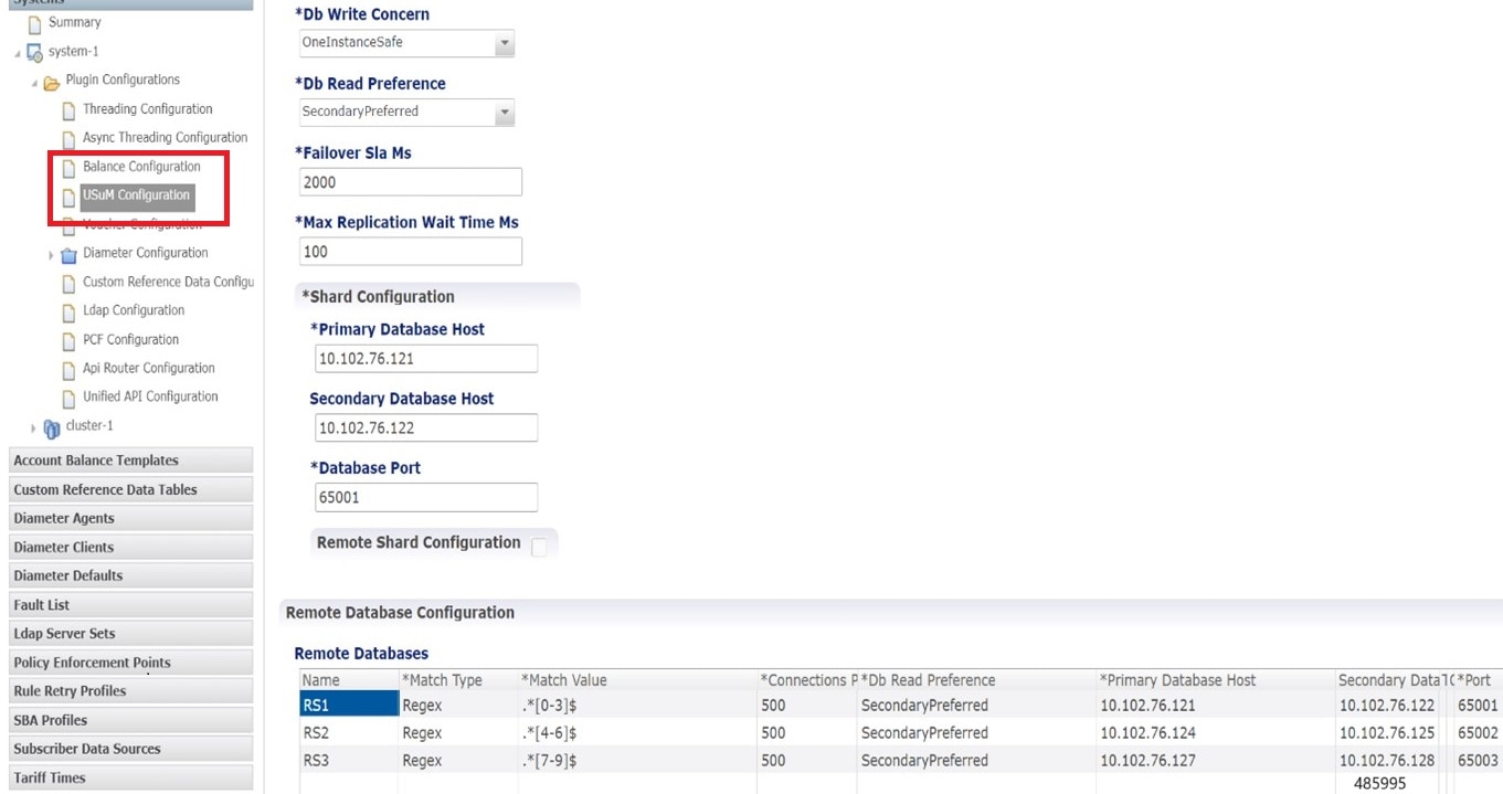
In the left pane of Policy Builder page, click Plugin Configurations option.

Step 2

Select USuM Configuration tab.

Step 3

Enter the mandatory Database values.


Dynamic QoS Uplift based on Subscriber QoS Schedule

The Dynamic QoS Uplift feature enables the adjustment of the QCI value for a subscriber session dynamically, based on predefined schedules. This manages the network resources and ensures optimal performance during peak times or for specific applications.

In addition to QCI uplift, CPC supports dynamic uplift of Access Point Name (APN) Aggregate Maximum Bit Rate (AMBR) for subscriber sessions using the same QoS schedule mechanism. The APN AMBR uplift is provisioned through the Subscriber Profile Repository (SPR) and applied based on the configured APN, validity time window, and priority. When the QoS schedule becomes active, CPC applies the provisioned uplink and downlink AMBR values to the matching subscriber sessions. At the end of the configured time window, CPC automatically reverts the AMBR values to those that were effective prior to the uplift. This enhancement ensures deterministic, time-bound bandwidth management and consistent QoS enforcement across Gx and N7 interfaces.

When multiple QoS schedules are provisioned for a subscriber, CPC evaluates the priority attribute associated with each schedule to determine the effective QoS profile. If priorities are configured, the QoS schedule with the highest priority takes precedence. If multiple schedules have the same priority, the schedules are rejected and the currently active QoS remains unchanged. If priority is not configured, CPC uses the start time to determine the applicable QoS schedule. This priority-based evaluation applies to both QCI and APN AMBR parameters.

QoS schedule management for a subscriber

Provision QoS schedule

Use these API queries to create or edit subscriber data and provision the QoS schedule for a subscriber:

  • CreateSubscriberRequest

  • UpdateSubscriberRequest

Here is an example to provision the QoS schedule:

<qosSchedule>
  <id>5</id>
  <qci>5</qci>
  <apn>APN_A</apn>
  <startDate>2024-08-27T11:50:00.000Z</startDate>
  <endDate>2024-08-27T11:50:59.000Z</endDate>
  <apnAmbrUl>45000</apnAmbrUl>
  <apnAmbrDl>45000</apnAmbrDl>
  <priority>1</priority>
</qosSchedule>

QoS schedule fields

The QoS schedule supports APN-level and DNN-level AMBR configuration with priority-based evaluation. A QoS schedule includes an identifier, a validity window, interface-specific QoS parameters, and an optional priority. The supported fields vary depending on the interface (Gx or N7).

Gx Interface

The following QoS schedule fields are supported for Gx-based subscriber sessions:

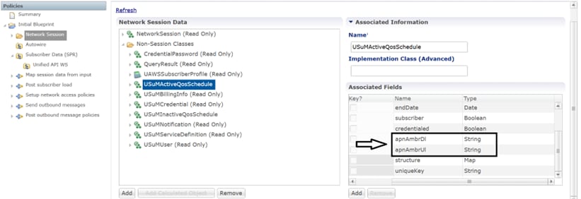
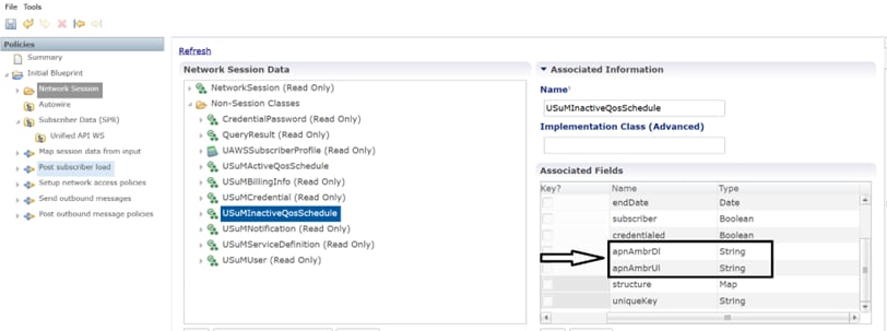
  • apnAmbrUl (Integer): Specifies the uplink Access Point Name (APN) Aggregate Maximum Bit Rate (AMBR) applied while the QoS schedule is active.

  • apnAmbrDl (Integer): Specifies the downlink Access Point Name (APN) Aggregate Maximum Bit Rate (AMBR) applied while the QoS schedule is active.

Here is an example to provision the QoS schedule:

<qosSchedule>
  <id>5</id>
  <gci>5</gci>
  <apn>APN_A</apn>
  <startDate>2025-10-17T11:50:00.000Z</startDate>
  <endDate>2025-10-17T11:51:00.000Z</endDate>
  <apnAmbrUl>45000</apnAmbrUl>
  <apnAmbrDl>45000</apnAmbrDl>
</qosSchedule>

Configuration for Gx

Figure 11. Gx-Based Subscriber QoS Schedule Configuration — USuMActiveQoSSchedule APN AMBR Fields
Figure 12. Gx-Based Subscriber QoS Schedule Configuration — USuMInactiveQoSSchedule APN AMBR Fields

N7 Interface

For N7-based sessions, CPC supports dynamic QoS scheduling using DNN-specific parameters. QoS schedules can include 5QI and aggregate DNN AMBR values with an optional priority.

When a QoS schedule becomes active, CPC applies the provisioned QoS parameters to matching subscriber sessions on the N7 interface based on the configured validity window and priority. Upon schedule expiry, CPC automatically restores the QoS values that were effective prior to the uplift.

The following QoS schedule fields are supported for N7-based subscriber sessions:

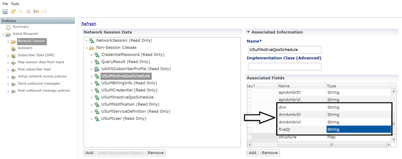
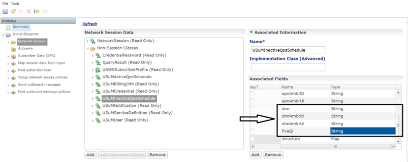
  • dnn (String): Specifies the Data Network Name (DNN) to which the QoS schedule applies.

  • fiveQi (Integer): Specifies the 5QI value applied while the QoS schedule is active.

  • dnnAmbrUl (Integer): Specifies the uplink DNN Aggregate Maximum Bit Rate (AMBR) applied while the QoS schedule is active.

  • dnnAmbrDl (Integer): Specifies the downlink DNN Aggregate Maximum Bit Rate (AMBR) applied while the QoS schedule is active.

  • priority: Defines the precedence of the QoS schedule when multiple schedules exist for a subscriber.

Here is an example to provision the QoS schedule:

<qosSchedule>
  <id>1</id>
  <fiveQi>5</fiveQi>
  <dnn>DNN_A</dnn>
  <startDate>2025-10-17T11:50:00.000Z</startDate>
  <endDate>2025-10-17T11:51:00.000Z</endDate>
  <dnnAmbrUl>45000</dnnAmbrUl>
  <dnnAmbrDl>45000</dnnAmbrDl>
  <priority>1</priority>
</qosSchedule>

Configuration for N7

Figure 13. N7-Based Subscriber QoS Schedule Configuration — USuMActiveQoSSchedule dnn Fields
Figure 14. N7-Based Subscriber QoS Schedule Configuration — USuMInactiveQoSSchedule dnn Fields

Note


  • The schedule includes the qosSchedule ID, QCI value, APN, start date, and end date.

  • There is no tag to support all APNs. To enable for ALL APN , do not send <apn> tag in the QoS schedule request.

  • In the start date and end date, the application supports hours and minutes fields without seconds. So, update the values as 00 seconds for start date and 59 seconds for end date fields.

  • The <apnAmbrUl> and <apnAmbrDl> elements specify the uplink and downlink APN AMBR values to be applied when the QoS schedule is active.

  • A lower numerical value indicates a lower priority. Priority comparison is applicable only when multiple QoS schedules are provisioned for a subscriber. When a single qosSchedule is provided and the priority attribute is not specified, CPC assigns a default priority value of 0

  • If multiple QoS schedules have the same priority, CPC rejects those schedules and retains the existing QoS configuration.

  • If priority is not specified and multiple schedules share the same start date, the schedules are rejected.

  • If priority is not specified and start dates differ, CPC applies the QoS schedule based on the start date.

  • If priority is specified for one QoS schedule and not specified for another, CPC assigns the lowest priority to the QoS schedule without an explicit priority value.


CPC sends a Re-Auth Request (RAR) to the Packet Gateway (PGW) to adjust the QCI value at the start and end times specified in the schedule. Multiple QoS schedules can be defined for different APNs for a single subscriber.

View QoS schedule information

Use the GetSubscriberRequest API to view the QoS Schedule information after provisioning the QoS schedule.

Delete expired QoS schedules

Send UpdateSubscriberRequest with empty values in the qosSchedule to delete all expired schedules.

Multiple session handling

CPC matches the sessions with the provisioned APN and send RARs to adjust the QCI value at the configured start and end times.

For subscribers with multiple active sessions using different APNs, CPC applies the APN AMBR uplift only to the sessions whose APN matches the value specified in the QoS schedule. Sessions established after the start time and before the end time of an active QoS schedule are immediately created with the provisioned AMBR values. At the end time, CPC reverts the AMBR values for the affected sessions to the values that were active before the QoS schedule was applied.

Feature Description

CPC needs to support configuration to accept inputs for next hop route for route rating, application Id, destination host, destination realm, next hop realm, next hop destination, and next hop destination rating.

When the diameter connection gets set up, the DRA displays the origin host and realm values, and all diameter application messages includes the actual host origin host and realm. CPC requires a method to determine the DRA connection that delivers the message to the desired host.

CPC sends the Diameter Request Messages to check the next hop route matches for the message’s application Id, destination host, and destination realm. If there is any match for the next hop routes, the message is sent to the Diameter Peer mapped to the next hop destination and next hop realm.

For multiple next hop routes, there are multiple next-hop destinations with the same or different ratings. CPC needs to find the next hop realm and destination combo that carries higher ratings for the next next hop destination and deliver the message for a combination of the application Id, destination host, and destination realm..

How It Works

This section describes how Next Hop Routing Support feature works.

Feature Configuration

This section describes how to configure the Next Hop Routing Support.

To configure the Next Hop Routing Support, use this configuration:

config 
  diameter 
    next-hop-route* [application-id destination-realm destination-host rating] 
    application-id       -> /diameter/application/application-id  
    destination-realm   string 
    destination-host    string 
    rating              int32 
    next-hop-realm   string 
    next-hop-host*  [next-hop-host-name] 
    next-hop-host-name  string 
        rating?         int32 
        end 

NOTES:

  • next-hop-route—Specifies the next hop realm and next next-hop-host details for a combination of application-id, destination-host and destination-realm of the outgoing diameter request message.

  • application-id—Specifies the Auth-Application-Id from diameter request message.

  • rating—Specifies the rating of the route.

  • destination-realm—Specifies the Destination-Realm from the diameter request message.

  • destination-host—Specifies the Destination-Host from the diameter request message.

  • next-hop-realm—Specifies the peer-realm configured in the diameter client stack at the CPC which need to be used for combination of application-id, destination-host and destination-realm in the diameter request message.

  • next-hop-host—Specifies the details about the next hop host to be used with host name and rating:

    • next-hop-host-name—Specifies the peer-host configured in the diameter client stack at the CPC which need to be used for combination of application-id, destination-host and destination-realm in the diameter request message

    • rating—Specifies the rating of the next-hop-host-name. Higher rated destination host will be selected when multiple destination-hosts are configured and reachable.

Configure indirect SCP communication model D

Feature description

Table 9.

Feature Name

Release Information

Description

Configure indirect SCP communication model D

2026.03.0

The indirect Service Communication Proxy (SCP) Model D feature enables the Converged Policy (CPC) to discover and route through an SCP. This architecture centralizes policy decision points across 5G interfaces, which reduces configuration overhead by offloading discovery tasks to the SCP. This improves interoperability and simplifies session policy correlation in multi-vendor 5G core networks.

The indirect Service Communication Proxy (SCP) Model D enables the Converged Policy (CPC) and Policy Control Function (PCF) to discover and route traffic through an SCP rather than communicating directly with target Network Functions (NFs). This phase extends support to the Access and Mobility Management Function (AMF), Application Function (AF), Charging Function (CHF), and Unified Data Repository (UDR) across the N5, N15, N28, and N36 interfaces. This architecture centralizes policy decision points, which reduces configuration overhead by offloading discovery tasks to the SCP.

Configure the indirect SCP communication model

Before you begin

Before you configure this feature, ensure that you meet these requirements:

  • Ensure the cluster runs version 1.24 or later.

  • Confirm that all SCP endpoints are resolvable and reachable from the PCF REST-EP pods.

  • Verify that existing Network Repository Function (NRF) discovery configurations for N5, N15, N28, and N36 are active to support fallbackToDirect.

  • Ensure you have administrative privileges in the PCF Ops-Center.

Use this procedure to establish connectivity to the SCP middleware, enable the Model D feature, and set NF binding IDs.

Procedure


Step 1

Log in to the CPC Ops-Center CLI.

Step 2

Enter config mode and configure the CA certificate to establish trust with the SCP:

pcf-tls
 ca-certificates <ca-name>
  cert-data <ca-pem-data>
 exit

Step 3

Configure the server certificate for the CPC:

certificates <server-cert-name>
  cert-data <server-pem-data>
  private-key <server-private-key>
 exit

Step 4

commit the configuration.


Configure the SCP profile

Define the SCP profile to establish the connection path to the SCP middleware.

Procedure


Step 1

Enter config mode.

Step 2

Define the SCP profile using the profile nf-client structure:

profile nf-client nf-type scp
 scp-profile <scp-profile-name>
  locality <locality-name>
  service name type nscp-routing
   endpoint-profile <endpoint-profile-name>
    capacity <capacity-value>
    priority <priority-value>
    uri-scheme https
    version uri-version v1
    endpoint-name <endpoint-name>
     primary ip-address ipv4 <scp-ip> port <scp-port>
    exit
   exit
  exit
 exit
exit

Step 3

commit the changes.


Enable Model D and mapping interfaces

Enable the global Model D and assign the SCP profile to the specific interfaces.

Procedure


Step 1

Enter config mode.

Step 2

Enable the global Model D feature: rest-endpoint model-d enabled.

Step 3

Link the SCP profile defined in the previous procedure: rest-endpoint model-d scp-profile <scp-profile-name> priority 1 locality <locality-name>

Step 4

Enable the required interfaces for SCP routing:


rest-endpoint model-d interfaces n5-callbacks true

rest-endpoint model-d interfaces n15-callbacks true

rest-endpoint model-d interfaces n28-chf true

rest-endpoint model-d interfaces n36-udr true

Step 5

Configure the fallback behavior to ensure PCF reverts to direct NRF discovery if the SCP is unreachable:

rest-endpoint model-d fallbackToDirect true
rest-endpoint model-d scpMaxRetries 2

Step 6

commit the changes.


Configure NF Binding IDs

Configure the NF instance identity to ensure the SCP correctly identifies the CPC during routing.

Procedure


Step 1

Enter config mode.

Step 2

Configure the NF instance and set IDs:

service-registration profile nf-instance-id <instance-id>
service-registration profile nf-set set-id <set-id>

Step 3

commit the changes.


Verify the configuration

Use this procedure to validate that the system applies the Model D configuration.

Procedure


Step 1

Check the pcf:model_d_enabled gauge in the Prometheus dashboard to confirm the feature is active.

Step 2

Run show running-config command in the CPC Ops-Center to confirm the rest-endpoint model-d configuration is active.

Step 3

Confirm that the CPC routes requests through the SCP by checking the pcf:route_by_nftype_scp_total metric.


rest-endpoint model-d enabled
rest-endpoint model-d scp-profile scp1.local priority 1 locality L1
rest-endpoint model-d scp-profile scp2.local priority 2 locality L1
rest-endpoint model-d fallbackToDirect true
rest-endpoint model-d scpMaxRetries 2

Interpret results and troubleshoot

Table 10. Diagnostic metrics and troubleshoot

Metric or issue

Interpretation or corrective action

pcf:model_d_enabled gauge

A value of 1 indicates the feature is active.

pcf:route_by_nftype_scp_total

Confirms successful request processing via the SCP relay.

pcf:scp_retry_count

Tracks the number of fallbacks or retries due to SCP unavailability.

SCP reachability failure

Verify SCP reachability if the pcf:scp_retry_count metric increases consistently.

Header parsing errors

Review CPC logs for header parsing errors if the SCP fails to route requests to the target NF.

Binding failure

Confirm that the NF instance ID and NF set ID are correctly configured in the CPC Ops-Center.

Header stripping

Ensure the SCP does not strip required headers by comparing incoming request headers against 3GPP specification requirements.