Deploying the Connector 3 OVA (Single Interface)
This chapter provides information about how to download and deploy the Cisco Spaces: Connector 3 and obtain the URL for the connector GUI.
Before you begin
-
2 vCPU
-
4-GB RAM
-
120-GB hard disk
Procedure
|
Step 1 |
Download connector OVA to your local system. |
||
|
Step 2 |
Create a virtual machine (VM) in the ESXi server and deploy the downloaded Cisco Spaces: Connector OVA. |
||
|
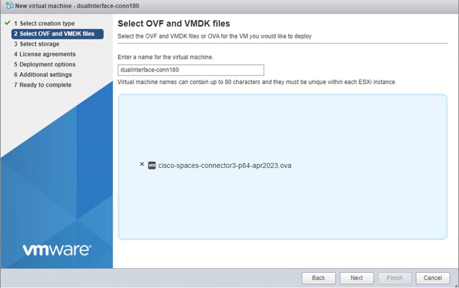
Step 3 |
In the 1. Select an OVF template window, click UPLOAD FILES, and select the corresponding connector OVA files or drag and drop the downloaded file, and click Next. 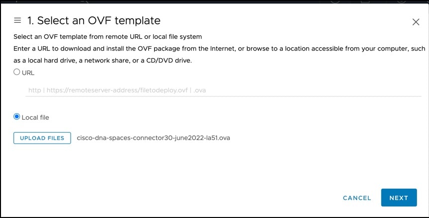
|
||
|
Step 4 |
In the 2. Select a name and folder window, enter a name for the VM, and choose a location for the VM, and click Next. 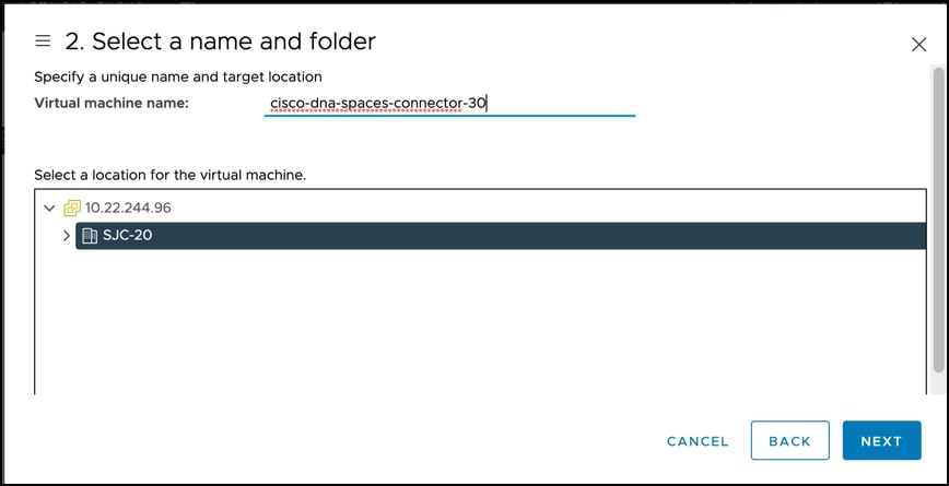
|
||
|
Step 5 |
In the 3. Select a compute resource window, select a destination compute resource, and click Next. 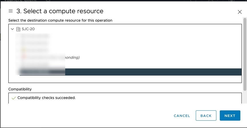
|
||
|
Step 6 |
In the 4. Review details window, read and verify the template details, and click Next. 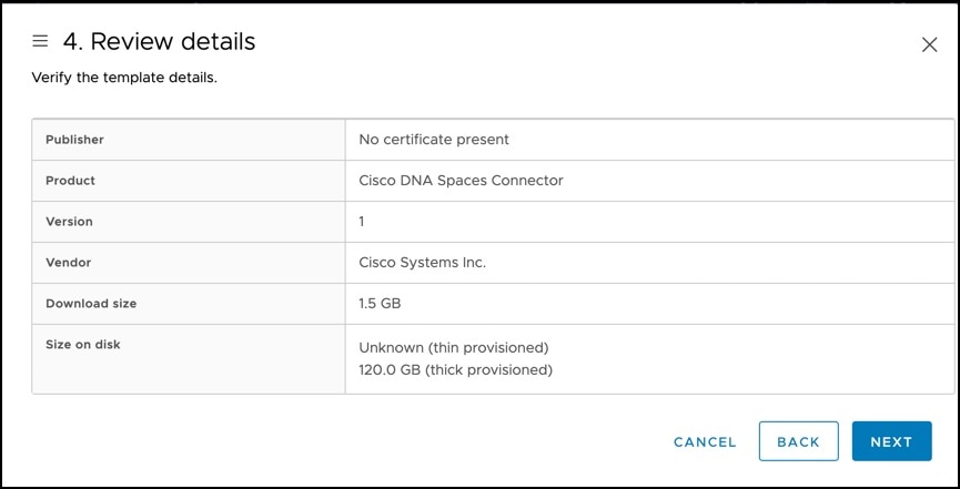
|
||
|
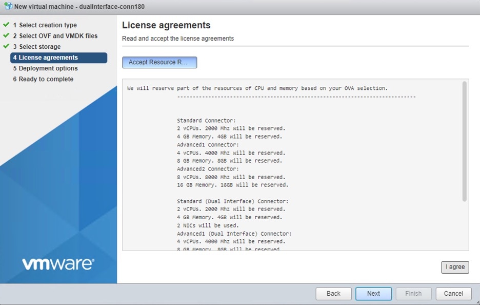
Step 7 |
In the 5. License agreements window, read the license agreement that is displayed and scroll to the end. Check I accept all license agreements and then click Next. 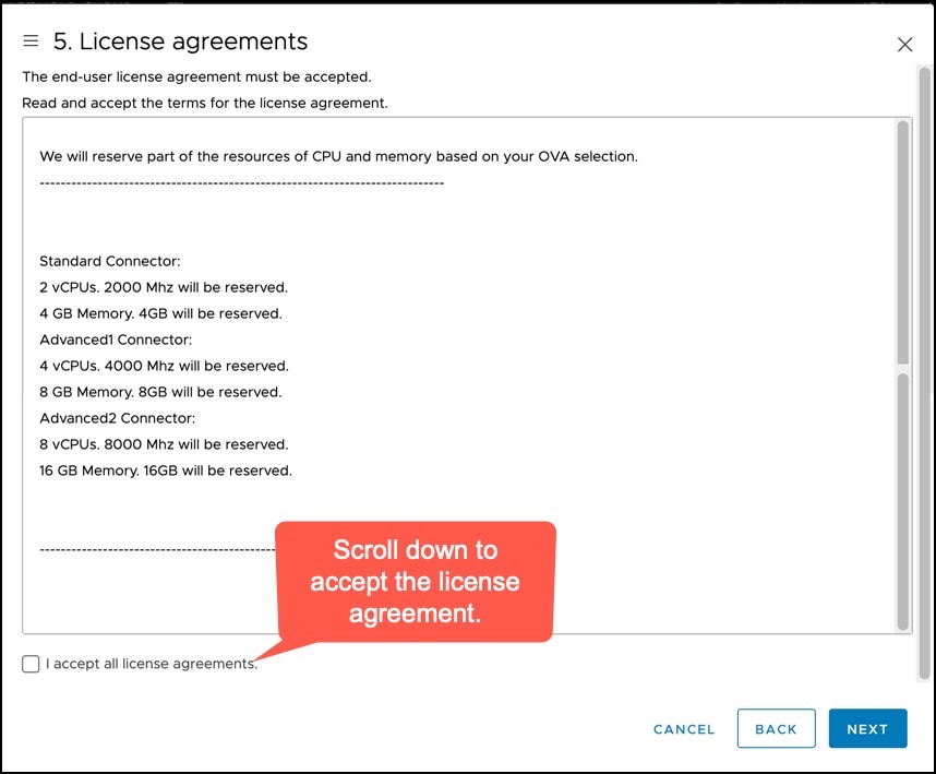
|
||
|
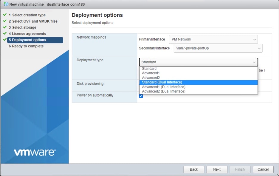
Step 8 |
In the 6. Configuration window, choose one of the following, and click Next.
|
||
|
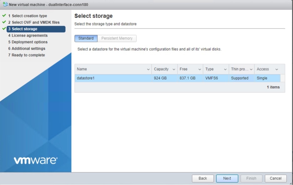
Step 9 |
In the 7. Select storage window, choose the standard storage configuration, and click Next. 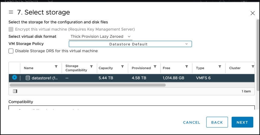
|
||
|
Step 10 |
In the 8. Select networks window, choose a destination network, and click Next. 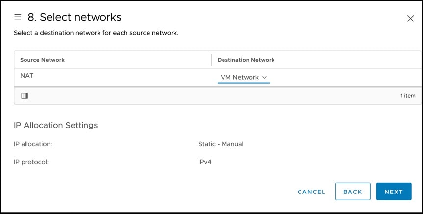
|
||
|
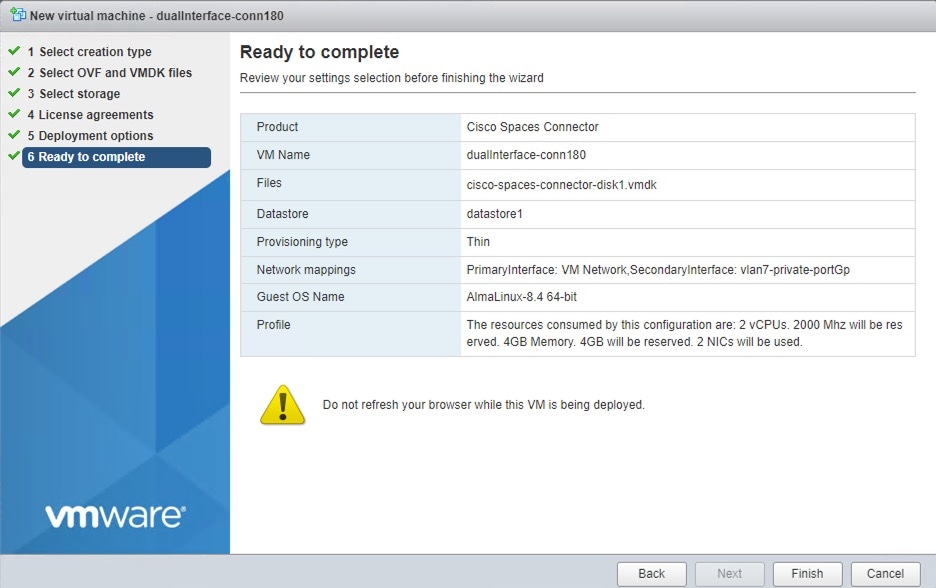
Step 11 |
In the 9. Ready to complete window, review the configurations and click Finish. 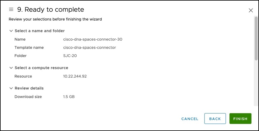
|
||
|
Step 12 |
Power on your VM and log in to the terminal and enter the default username root and default password root. 
|
||
|
Step 13 |
Choose an network interface to configure as PRIMARY. 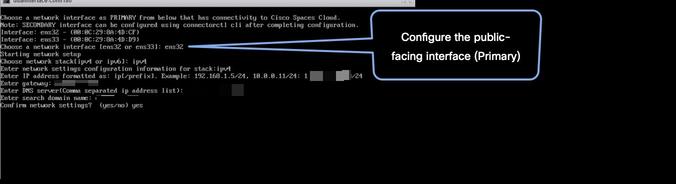
|
||
|
Step 14 |
Do one of the following, and then configure the network settings for the PRIMARY interface. Specify parameters such as IP address, hostname, and so on.
You can add multiple DNS servers as a comma separated list in this step. After the task is complete and the Cisco Spaces: Connector is deployed, you can login to the connector CLI, and run the connectorctl network config command to add more DNS servers or edit the existing list. |
||
|
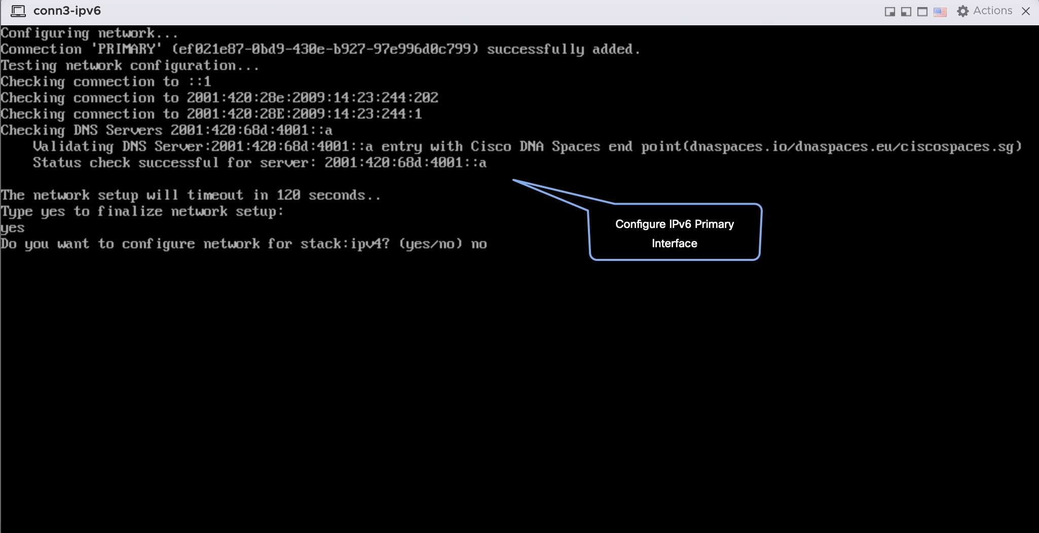
Step 15 |
Confirm the setup.
|
||
|
Step 16 |
Reset the password for the spacesadmin user.
|
||
|
Step 17 |
Enter the time zone. 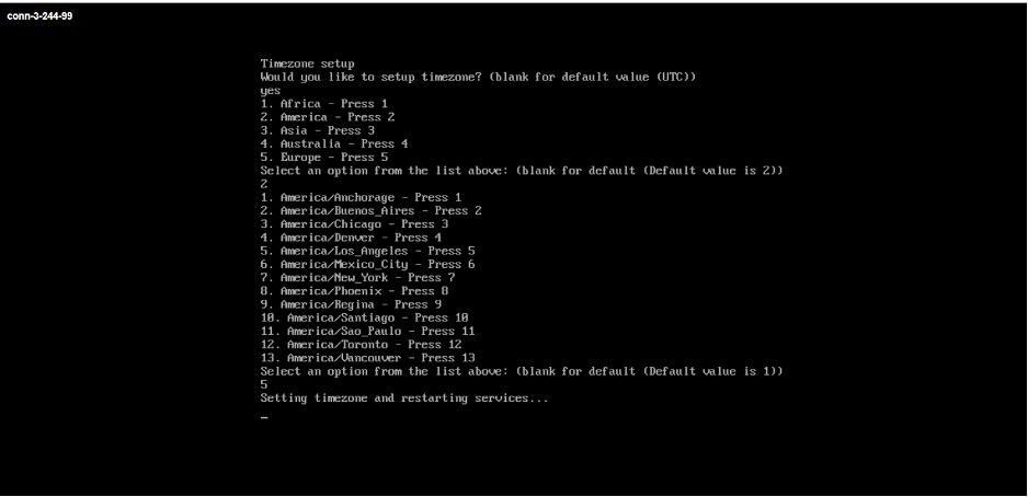
|
||
|
Step 18 |
Enter the Network Time Protocol (NTP) server name to synchronize the system time with that of NTP server, or leave it blank if you do not want to configure an NTP server. 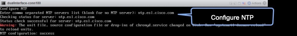

|
||
|
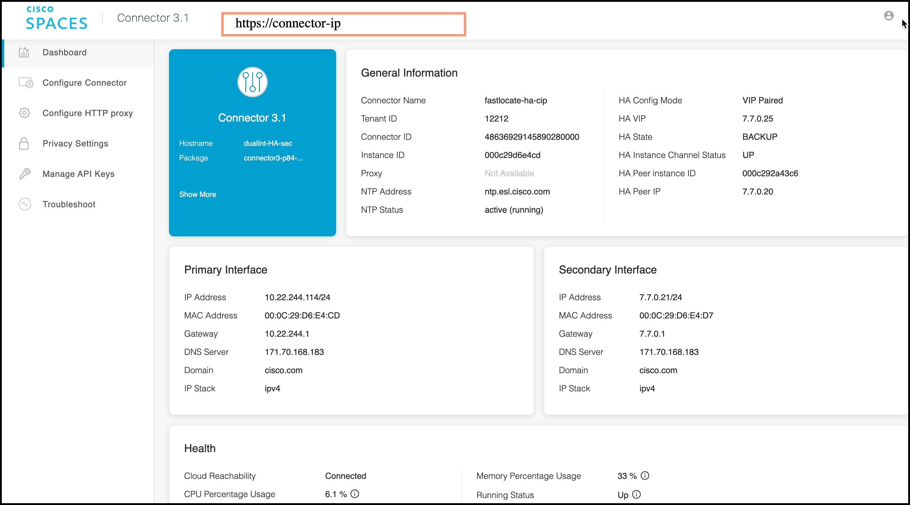
Step 19 |
Note the URL (https://connector-ip) before the automatic reboot. You can use this URL later to open the connector GUI. 
|
||
|
Step 20 |
In a browser window, enter the noted URL and press Enter to open the connector GUI. Log in as a spacesadmin user. 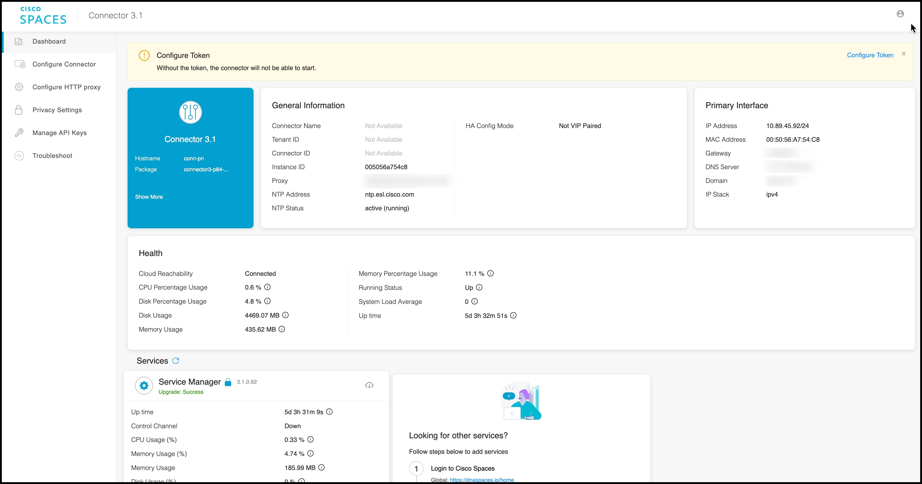
|
What to do next
You can now Configure this Connector on Cisco Spaces.

 Feedback