Features and Services Guide for Cisco Unified Communications Manager, Release 10.0(1)
Bias-Free Language
The documentation set for this product strives to use bias-free language. For the purposes of this documentation set, bias-free is defined as language that does not imply discrimination based on age, disability, gender, racial identity, ethnic identity, sexual orientation, socioeconomic status, and intersectionality. Exceptions may be present in the documentation due to language that is hardcoded in the user interfaces of the product software, language used based on RFP documentation, or language that is used by a referenced third-party product. Learn more about how Cisco is using Inclusive Language.
The following sections provide information about the Enhanced Location Call Admission Control feature.
Configure Enhanced Location Call Admission Control
The Enhanced Location Call Admission Control (CAC) feature improves the Location CAC mechanism to support complex network,
multi-tier, multi-hop topology. This feature supports Location CAC within a cluster and among multiple clusters and allows
end to end bandwidth deduction. This enhancement to the CAC feature creates a much more flexible and dynamic system for the
management of bandwidth.
The enhanced CAC feature provides a new service, called Location Bandwidth Manager (LBM). The LBM service can be configured
to run on every node or selected nodes of a Cisco Unified Communications Manager (Unified CM) server.
Perform the following steps to configure the Enhanced Location Call Admission Control
feature:
Procedure
Step 1
Activate the LBM service.
If a server is upgraded from pre-9.0 release, the LBM service is activated on all servers where the Cisco Callmanager service
is enabled. For a new system install, the LBM service must be manually activated on the desired nodes.
Step 2
Create an LBM group.
Each Unified CM server must communicate with an LBM. If LBM is not running on the same node, configure an LBM group and assign
the LBM group to the Unified CM server.
Step 3
Model the network using locations and links.
Step 4
Add the locations for the system.
By default, when a new location is created, a link from the newly added location to the Hub_None is added as well, with unlimited
audio bandwidth, 384 kbps video bandwidth and 384 kbps immersive video bandwidth. This can be adjusted to match the model
and if needed the link to the Hub_None location can be deleted.
Step 5
Assign intra-location bandwidth to the location, if the default of unlimited bandwidth is not desired.
Step 6
Add links from one location to other locations (inter-location). And assign bandwidth allocations and weight to the links.
If you are enabling intercluster Enhanced Location CAC complete the following steps:
Step 7
Configure the LBM Hub Group page to allow the LBM servers acting as Hubs to find LBM servers in remote clusters and establish
external communication with those clusters.
Any LBM servers that are assigned an LBM Hub Group establish communication with all other LBM servers assigned the same or
an overlapping LBM Hub Group.
Step 8
Assign the SIP ICT that is used to route calls between clusters to the system location Shadow.
Enhanced Location Call Admission Control Feature
The following sections provide information on the Enhanced Location Call Admission Control feature.
Terminology for Enhanced Location Call Admission Control
This document uses the following terms to discuss Enhanced Location Call Admission Control (CAC):
Link: Links interconnect locations and are used to define the bandwidth available between locations.
Weight:The relative priority of a link in forming the effective path between any pairs of locations. Weights are used on links to
provide a "cost" to the "effective path". The effective path has the least cumulative weight of all other paths. Weights are pertinent only when there is more than
1 path between any 2 locations.
Locations: A Location represents a LAN. It could contain endpoints or simply serve as a transit location between links for WAN network
modeling
Bandwidth Allocation: The amount of bandwidth allocated in the model for each type of traffic: audio, video, and immersive video (Telepresence).
Path: A sequence of links and intermediate locations connecting a pair of end locations. Only one effective path between a pair
of end locations is used
Locations Bandwidth Manager: A service that assembles a network model from configured location and link data in one or more clusters, determines the effective
paths between pairs of locations, determines whether to admit calls between a pair of locations based on the availability
of bandwidth for each type of call, and deducts (reserves) bandwidth for the duration of each call that is admitted.
Locations Bandwidth Manager Hub: An LBM service that has been designated to participate directly in inter-cluster replication of fixed and dynamic data. LBMs
assigned an LBM hub group discover each other through their common connections and form a fully meshed replication network.
Other LBM services in a cluster with an LBM hub participate indirectly in inter-cluster replication through the LBM hubs in
their cluster.
Shadow location: SIP Inter-cluster Trunks must be assigned to the Shadow location to enable proper inter-cluster operation of this feature.
SIP trunks to devices with a specific location, such as SIP Gateways, may be assigned to ordinary locations. A Shadow location
is a special location that has no links to other locations and no bandwidth allocations.
Limitations of Bandwidth Management Prior to Release 9.0
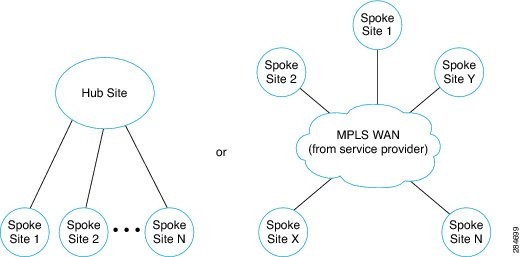
Previously Unified CM Location Call Admission Control (CAC) could only effectively support the simple Hub and Spoke location
model, such as remote sites connected to a main site or all sites connected to an MPLS-based IP WAN.
Figure 1. Hub and Spoke Location Model
Many customer networks do not conform to the Hub and Spoke location model; therefore customers need to have a Location CAC
mechanism that better models the path that media actually travel through the network.
There are many deployments where multiple Unified CM clusters manage devices in the same physical site, for example, multiple
Unified CM clusters manage phones in the same branch. When phones call each other within the same site but are managed by
different clusters, bandwidth may be deducted (reserved) unnecessarily, which may cause blocking of other calls. Adding video
calls and immersive video calls to the network exacerbates these issues because video calls consume more bandwidth than audio
calls.
When Session Manager Edition (SME) attempts to manage bandwidth between clusters it can only assign location bandwidth to
trunks connecting the SME and the leaf clusters, not reflecting the fact that media is may not be traversing the SME.
Enhancement to Bandwidth Management Solution
The bandwidth management solution has been enhanced to support complex network models, including multi-tier, multi-hop topology.
In these models audio and video calls can traverse multiple network links and locations and deduct bandwidth across each
link. Enhanced network model is structured as follow:
When two locations are directly connected, a link is modeled between them.
Weights are assigned to the links to model the actual media path between two locations.
Audio, video, and immersive video bandwidth capacity are assigned to each link and location.
Bandwidth deductions are made from each link and from each location along the media path.
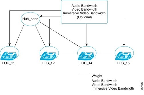
The following graphic represents a simple Location CAC topology model.
Figure 2. Simple Location CAC Model
Enhanced Location Call Admission Control Architecture
The following sections provide information about Enhanced Location Call Admission Control architecture.
Model-Based Call Admission Control
Enhanced Location Call Admission Control (CAC) is a model-based CAC mechanism. The administrator creates a model of the network
and how the network infrastructure handles the media.
Note
The more accurate and detailed the model of the network is, the more effective the management of the bandwidth and avoidance
of congestion is within the network. However, the model cannot account for transient network failure conditions.
Through the Cisco Unified Communications Manager interface the administrator configures the Enhanced Location CAC mechanism based on the network model.
After the administrator creates the model and enters it into Cisco Unified Communications Manager database, Location Bandwidth Manager (LBM) calculates the effective paths between all originating and terminating locations,
and deducts bandwidth from each link and location along that path.
When a call is admitted between two locations, LBM deducts (reserves) bandwidth from each link and location along that path
for the duration of the call. The bandwidth deduction is symmetric (bidirectional). For example, for a G.711 audio call, 80
kb bandwidth is deducted from the audio allocation assigned to each link and location in the call path. When a call is terminated,
LBM restores the bandwidth deduction.
The administrator may assign bandwidth allocations to locations as well as to links, if it is desired to limit admission of
intra-location as well as inter-location calls.
Note
The intra-location bandwidth allocations are unlimited by default.
Location Bandwidth Manager
A Location Bandwidth Manager (LBM) can reside and run on every Cisco Unified Communications Manager node, or on a few selected Cisco Unified Communications Manager nodes within the cluster. LBM is a feature service and can be started and stopped from the serviceability configuration page.
Main functions of Location Bandwidth Manager are:
Model Formation and path determination
Replication of the model to other LBMs within the cluster, and between clusters
Servicing bandwidth requests from Unified CM
Replication of bandwidth deductions to other LBMs within the cluster, and between clusters
Provide configured and dynamic information on request to Serviceability
Update Location RTMT counters
When LBM service is started, it reads configured location information from the local database. This includes configured locations;
audio, video, and immersive video capacities in those locations; links from a given location to other locations, the weight
associated with those link; and the audio, video, and immersive video capacities on those links. It creates a local model
with these values. Other LBMs in the cluster have access to the same data from the database and thus create the same local
model at their startup. The LBM is now synchronized with the rest of the cluster and is ready to provide service.
Each Cisco Callmanager service communicates with LBM services within the cluster, as designated by an LBM group. By default,
each Cisco Callmanager service communicates with the local LBM within the cluster.
Each LBM service communicates with all other LBMs within the cluster and may communicate through LBM Hubs with LBM services
in other clusters. LBM services within the cluster are fully meshed.
The LBM service computes the effective path from the source location to the destination location by adding the weight of each
link for each possible path between source and destination. The path with the least cumulative weight is designated as the
effective path. If there is more than one path that has the same weight LBM chooses which path to use. All calls that have
the same source and destination locations use the same path.
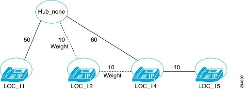
The following figure provides an example, demonstrating the calculation of the effective path from Hub_none to Loc_14:
A path from Hub_none through Loc_12 to Loc_14 is the effective path with a total weight of 20.
A path from Hub_none to Loc_14 has weight of 60 which is greater than 20 and therefore not the effective path.
LBM group configuration allows the administrator to select the LBM service that Cisco Unified Communications Manager can communicate with.
It is not necessary to run the LBM service on every Cisco Unified Communications Manager node.
The administrator can configure the LBM group based on consideration to minimize the network delay for bandwidth deduction.
The LBM group can provide redundancy of LBM service to maintain the availability of CAC mechanism during network outage.
When Cisco Unified Communications Manager is trying to locate the LBM service to communicate with:
It honors the LBM group association if one exists
If there is no LBM group assigned or an empty LBM group is assigned, Cisco Unified Communications Manager uses a local LBM if it is activated
If there is no LBM available, then Cisco Unified Communications Manager uses a service parameter to determine how to treat the call
When selectively activating LBM services and configuring the LBM groups consider the following:
Activate at least one LBM on each distinct call processing site. Consider activating LBM on standalone servers.
For split data center deployment, activate at least one LBM for each data center.
Consider activating LBM on the stand-by servers where there are active and stand-by servers to reduce the impact on the active
servers.
Connect to a local LBM service when available.
For clusters with multiple sites, select LBM services in the data center or in the closest regional site.
Inter-Cluster Location Call Admission Control
With the model-based Location CAC between clusters (intercluster), each Cisco Unified Communications Manager cluster has a local model that it controls. Through an intersystem replication mechanism, each system in the enterprise network
propagates its local model to other systems and creates a global model of the entire enterprise network by putting in each
model from the remote systems, and storing it in the internal memory. LBM services in each system in the enterprise network
that participate in the intercluster location CAC, has the global model stored in its local memory.
When a call is made across the clusters, originating and terminating systems pass their locations and call identifiers to
each other through the signaling protocol (e.g. SIP signaling protocol). Terminating and originating clusters reserve location
CAC bandwidth end to end locally, using its global location CAC model, and then replicate the bandwidth reservation to other
systems in the enterprise network.
Note
The amount of intersystem bandwidth replication messages can be significant. Select LBM Hubs carefully to make replication
more efficient within the enterprise network.
Race conditions may occur as each local system reserves bandwidth from the global model and then replicates the deduction.
When race conditions occur, calls may be admitted in excess of those for which bandwidth is deducted.
Note
When modeling the network, use conservative bandwidth capacity assumptions to allow for the fact that calls may be admitted
in excess of those for which bandwidth is deducted.
The following are some considerations when configuring intercluster location CAC between a local cluster and a remote cluster:
The local administrator must configure the remote locations adjacent to local locations and the links between local and remote
locations.
When the local cluster receives a model replication from a remote cluster, it joins the models by identifying locations and
links that appear in both models and forms a global network model.
It is critical to name locations consistently in all clusters, to ensure the global network model assembles correctly. Follow
the principle of same location, same name; different location, different name.
Note
If there is a conflict in bandwidth capacity or weight assignment on the common links or locations, the local cluster uses
the minimum of the assigned values.
Intercluster Location Call Admission Control Replication
An Enhanced Location CAC LBM replication network is used to replicate the model topology, and bandwidth deduction across multiple
clusters, and within the cluster. All LBM services are fully connected within the cluster and all LBM Hubs are fully connected
between clusters. LBM services that are not LBM Hubs participate in intercluster replication only through the LBM Hubs in
their cluster.
The LBM Hub Group provides the mechanism for an LBM Hub to find out how to communicate with other LBM Hubs in remote clusters.
By this mechanism, the LBM Hub builds a fully meshed replication network with all other LBM Hubs.
Location Bandwidth Manager Hubs
The following describes Location Bandwidth Manager (LBM) Hubs:
An LBM service becomes a Hub when an LBM Hub Group is assigned to it.
If a cluster has multiple LBM Hubs, the LBM Hub with the lowest IP Address functions as the sender of messages to other remote
clusters.
The LBM Hub organizes its links to remote LBM Hubs by the ClusterId assigned to it.
The LBM Hub that functions as the sender for messages, and picks the first LBM Hub of each cluster to send messages to.
The LBM Hub that receives messages from the remote clusters, forwards the received messages to other LBM services within the
cluster.
Location Bandwidth Service Parameters
Service parameters for Enhanced Location Call Admission Control
There are three new service parameters for Enhanced Location CAC:
Unified CM to LBM Periodic Reservation Refresh Timer: This parameter specifies the time duration in minutes that Cisco Unified Communications Manager refreshes the active bandwidth
reservations to the Cisco Location Bandwidth Manager.
Call Treatment When No LBM Available: This parameter specifies whether Cisco Unified Communications Manager allows or rejects calls when there is no Cisco Location
Bandwidth Manager available for location-based call admission control.
Locations Media Resource Audio Bit Rate Policy: This parameter determines the bit rate value to deduct from the audio bandwidth pools within and between the locations of
the parties for an audio-only call when a Media Resource such as a transcoder is inserted into the media path and for more
complex scenarios.
Shadow System Location
Shadow Location
Shadow is a new system location created for intercluster Enhanced Location CAC. In order to pass location information across
clusters, the SIP ICT needs to be assigned to the system location Shadow.
The system location Shadow:
Is a valid location only for a SIP ICT. Devices other than SIP trunks assigned incorrectly to the Shadow location are treated
as if assigned to the Hub_None location.
Cannot have a link connecting to other user defined locations, so bandwidth cannot be deducted between the Shadow location
and other user defined locations.
Has no intra-location bandwidth capacities, so bandwidth cannot be deducted within the Shadow location.
Note
SIP trunks, including ICTs, may be assigned to fixed locations, if their destination does not participate in intercluster
Enhanced Location CAC.
Devices That Support Enhanced Location Call Admission Control
Device support
Unified CM and LBM manage bandwidth for all types of end devices, including IP phones, gateways, and H.323 and SIP trunk destinations.
However, inter-cluster Enhanced Locations CAC requires SIP ICTs assigned to the system location Shadow. All other types of
devices are supported only when assigned to ordinary (fixed) Locations.
Unified CM and LBM do not manage bandwidth for media resources; calls are modeled and bandwidth reserved between the locations
of end devices only. For cases in which media resources change the bandwidth requirement for a call, the customer has the
option to change a global parameter setting that determines whether the minimum or maximum bandwidth is reserved.
Enhanced Call Admission Control Limitations
Limitations
The model created by the system is not perfectly synchronized at all times; excess calls may be admitted due to race conditions.
Use conservative bandwidth allocations in the model to allow for this possibility.
During network failure conditions, the bandwidth reservation path calculated by Unified CM may not accurately reflect network
conditions. There is no satisfactory way to allow for this scenario in the model.
If video capabilities are enabled, then bandwidth for audio will be allocated from video.
Location Bandwidth Manager Security
Location Bandwidth Manager Security Mode
LBM is able to secure its intercluster communications between LBM hubs and in order to support backward compatibility and
upgrades LBM has an option to configure how intercluster LBM hubs communicate with each other. To meet these requirements,
the enterprise service parameter, LBM Security Mode, is available with the following values:
Secure
Insecure
Mixed
The default setting is Insecure. You enable LBM secure communication by changing this Enterprise service parameter to either
Secure or Mixed. And when this service parameter is changed, the LBM hubs in that cluster need to be restarted so that connections
with the new security setting can be attempted.
The Mixed configuration is insecure, but very flexible and allows Unified CM Release 9.1 and later clusters to communicate
with Unified CM Release 9.0 clusters, the latter operating in the strict insecure mode. This is an intermediate step while
converting all the clusters from insecure to secure mode or secure to insecure mode. A description of this would be: starting
with the clusters in insecure mode, make sure all the certificates are present on all nodes using, for instance, the Bulk
Certificate export/import. Change the parameter to Mixed without losing communication (except when the LBM hubs are restarted).
After all the clusters are moved into Mixed and all LBM hubs are confirmed to have secure connections to all other hubs, switch
to Secure mode. Similar steps involving intermediate mixed state can be followed to move to insecure from secure.
The Enterprise service parameter is used by LBM to determine whether an LBM hub accepts and attempts secure only, insecure
only, or both, connections from or to a remote LBM hub.
LBMs has one port for secure connections (9005), one for insecure connections (9004). The insecure port 9004 has been defined
since Unified CM 9.0 release. Secure port 9005 is added for Unified CM Release 9.1.
The communication between LBMs within the cluster remains through the insecure connections.
An LBM hub accepts connections from remote LBM hubs:
If the Enterprise service parameter is set to Mixed, an LBM hub in this cluster accepts both secure and insecure connections
from remote LBM hubs.
If the Enterprise service parameter is set to Insecure, an LBM hub only accepts insecure connections from remote LBM hubs.
If the Enterprise service parameter is set to Secure, an LBM hub only accepts secure connections from remote LBM hubs.
An LBM hub attempts to open a connection to remote LBM hubs:
If the Enterprise service parameter is set to Mixed, an LBM hub in this cluster attempts both secure and insecure connections
to remote LBM hubs, which is also based on validation and availability of local and remote security certificates.
If the Enterprise service parameter is set to Insecure, an LBM hub only attempts an insecure connection to remote LBM hubs.
If the Enterprise service parameter is set to Secure, an LBM hub only attempts a secure connection to remote LBM hubs. Secure
connections are based on validation and availability of local and remote security certificates.
In Unified CM Release 9.0 LBM two connections between each LBM were available, one connection for outgoing and one for incoming
insecure communication. For Unified CM Release 9.1, LBM two additional connections are available for LBM hubs connecting
between clusters for secure communication. Therefore there are up to 4 connections for the Mixed Mode service parameter for
LBM hubs connecting between clusters.
LBM selects a secure connection to send information, if a secure connection is available in its connection pool. If a secure
connection is not available, but an insecure connection is available, LBM sends information on the insecure connection. Under
race conditions when the connections are being established, it is possible that initially there are only insecure connections
available. However, LBM automatically switches to secure connections when those become available. This logic applies to connections
coming and going during the application lifetime. This illustrates one reason why mixed connections are inherently insecure.
Note
To use the Secure LBM feature where the LBM Security Mode is set to Mixed or Secure, Tomcat certificates for every node must
be deployed on each respective node. For more information about deploying certificates, see Cisco Unified Communications Operating System Administration Guide.

 Feedback