- Preface
- Software Licensing
- The Cisco IOS command-line interface (CLI)
- Configuring Interfaces
- Switch Alarms
- Initial Switch Configuration (IP address assignments and DHCP autoconfiguration)
- How to Setup and Use the Cisco Configuration Engine
- How to Create and Manage Switch Clusters
- Performing Switch Administration
- Configuring Precision Time Protocol (PTP)
- Configuring PROFINET
- Common Industrial Protocol (CIP)
- Configuring SDM Templates
- Configuring Switch-Based Authentication
- Configuring IEEE 802.1x Port-Based Authentication
- MACsec
- Web-Based Authentication
- Configuring Smartports Macros
- Configuring SGACL Monitor Mode and SGACL Logging
- Configuring SGT Exchange Protocol over TCP (SXP) and Layer 3 Transport
- Configuring VLANs
- VLAN Trunking Protocol (VTP)
- Configuring Voice VLAN
- How to Configure Spanning Tree Protocol (STP)
- Configuring MSTP
- Configuring Optional Spanning-Tree Features
- Configuring Resilient Ethernet Protocol
- Configuring the FlexLinks and the MAC Address-Table Move Update
- Configuring DHCP
- Dynamic Address Resolution Protocol (ARP)
- Configuring IP Source Guard
- How to Configure Internet Group Management Protocol (IGMP) and Multicast VLAN Registration (MVR)
- Configuring Port-Based Traffic Control
- Configuring LLDP, LLDP-MED, and Wired Location Service
- Configuring SPAN and RSPAN
- One-to-one (1:1) Layer 2 Network Address Translation (NAT)
- How to Configure CDP
- Configuring UniDirectional Link Detection (UDLD)
- Configuring RMON
- Configuring System Message Logging
- Configuring Simple Network Management Protocol (SNMP)
- Network Security with ACLs
- Configuring Quality of Service (QoS)
- Configuring Static IP Unicast Routing
- Configuring IPv6 Host Functions
- Configuring Link State Tracking
- Configuring IP multicast routing
- Configuring Multicast Source Discovery Protocol (MSDP)
- Configuring Multicast Listener Discovery (MLD) snooping
- Configuring HSRP and VRRP
- Configuring IPv6 access control lists (ACLs)
- Configuring Embedded Event Manager (EEM)
- IP Unicast Routing
- IPv6 Unicast Routing
- Unicast Routing Overview
- Configuring Cisco IOS IP SLAs Operations
- Configuring Dying-Gasp
- How to Configure Enhanced Object Tracking
- Configuring MODBUS TCP
- Configuring Ethernet CFM
- Working with the Flash File System
- How to Configure EtherChannels
- Troubleshooting
- How to use a Secure Digital (SD) flash memory module (SD card)
- Cluster Command Switch Characteristics
- Standby Cluster Command Switch Characteristics
- Candidate Switch and Cluster Member Switch C haracteristics
Configuring Switch Clusters
This chapter provides the concepts and procedures to create and manage switch clusters on your switch. You can create and manage switch clusters by using the command-line interface (CLI), Cisco Network Assistant (CNA) or SNMP. For information about CNA, see the online help for CNA.
This chapter provides information about switch clusters. It also includes guidelines and limitations for clusters mixed with other cluster-capable Catalyst switches, but it does not provide complete descriptions of the cluster features for switches in the cluster. For complete cluster information for a specific Catalyst platform, refer to the software configuration guide for that switch.
Cluster Command Switch Characteristics
A cluster command switch must meet these requirements:
■![]() Has Cisco Discovery Protocol (CDP) version 2 enabled (the default).
Has Cisco Discovery Protocol (CDP) version 2 enabled (the default).
■![]() Is not a command or cluster member switch of another cluster.
Is not a command or cluster member switch of another cluster.
■![]() Is connected to the standby cluster command switches through the management VLAN and to the cluster member switches through a common VLAN.
Is connected to the standby cluster command switches through the management VLAN and to the cluster member switches through a common VLAN.
Standby Cluster Command Switch Characteristics
A standby cluster command switch must meet these requirements:
■![]() Is connected to the command switch and to other standby command switches through its management VLAN.
Is connected to the command switch and to other standby command switches through its management VLAN.
■![]() Is connected to all other cluster member switches (except the cluster command and standby command switches) through a common VLAN.
Is connected to all other cluster member switches (except the cluster command and standby command switches) through a common VLAN.
■![]() Is redundantly connected to the cluster so that connectivity to cluster member switches is maintained.
Is redundantly connected to the cluster so that connectivity to cluster member switches is maintained.
Candidate Switch and Cluster Member Switch Characteristics
Candidate switches are cluster-capable switches that have not yet been added to a cluster. Cluster member switches are switches that have actually been added to a switch cluster. Although not required, a candidate or cluster member switch can have its own IP address and password (for related considerations, see IP Addresses and Passwords).
To join a cluster, a candidate switch must meet these requirements:
■![]() Is running cluster-capable software.
Is running cluster-capable software.
■![]() Is not a command or cluster member switch of another cluster.
Is not a command or cluster member switch of another cluster.
■![]() If a cluster standby group exists, the switch is connected to every standby cluster command switch through at least one common VLAN. The VLAN to each standby cluster command switch can be different.
If a cluster standby group exists, the switch is connected to every standby cluster command switch through at least one common VLAN. The VLAN to each standby cluster command switch can be different.
■![]() Is connected to the cluster command switch through at least one common VLAN.
Is connected to the cluster command switch through at least one common VLAN.
Catalyst 1900, Catalyst 2820, Catalyst 2900 XL, Catalyst 2950, and Catalyst 3500 XL candidate and cluster member switches must be connected through their management VLAN to the cluster command switch and standby cluster command switches. For complete information about these switches in a switch-cluster environment, refer to the software configuration guide for that specific switch.
This requirement does not apply if you have a Catalyst 2970, Catalyst 3550, Catalyst 3560, or Catalyst 3750 cluster command switch. Candidate and cluster member switches can connect through any VLAN in common with the cluster command switch.
Restrictions for Configuring Switch Clusters
We do not recommend using the ip http access-class global configuration command to limit access to specific hosts or networks. Access should be controlled through the cluster command switch or by applying access control lists (ACLs) on interfaces that are configured with IP address. For more information on ACLs, see Configuring Network Security with ACLs
Information About Configuring Switch Clusters
A switch cluster is a set of up to 16 connected, cluster-capable Catalyst switches that are managed as a single entity. The switches in the cluster use the switch clustering technology so that you can configure and troubleshoot a group of different Catalyst desktop switch platforms through a single IP address.
In a switch cluster, one switch must be the cluster command switch and up to 15 other switches can be cluster member switches. The total number of switches in a cluster cannot exceed 16 switches. The cluster command switch is the single point of access used to configure, manage, and monitor the cluster member switches. Cluster members can belong to only one cluster at a time.
Benefits of Clustering Switches
■![]() Management of switches regardless of their interconnection media and their physical locations. The switches can be in the same location, or they can be distributed across a Layer 2 or Layer 3 (if your cluster is using a Catalyst 3550, Catalyst 3560, or Catalyst 3750 switch as a Layer 3 router between the Layer 2 switches in the cluster) network.
Management of switches regardless of their interconnection media and their physical locations. The switches can be in the same location, or they can be distributed across a Layer 2 or Layer 3 (if your cluster is using a Catalyst 3550, Catalyst 3560, or Catalyst 3750 switch as a Layer 3 router between the Layer 2 switches in the cluster) network.
Cluster members are connected to the cluster command switch according to the connectivity guidelines described in the Automatic Discovery of Cluster Candidates and Members. This section includes management VLAN considerations for the Catalyst 1900, Catalyst 2820, Catalyst 2900 XL, Catalyst 2950, and Catalyst 3500 XL switches. For complete information about these switches in a switch-cluster environment, refer to the software configuration guide for that specific switch.
■![]() Command-switch redundancy if a cluster command switch fails. One or more switches can be designated as standby cluster command switches to avoid loss of contact with cluster members. A cluster standby group is a group of standby cluster command switches.
Command-switch redundancy if a cluster command switch fails. One or more switches can be designated as standby cluster command switches to avoid loss of contact with cluster members. A cluster standby group is a group of standby cluster command switches.
■![]() Management of a variety of switches through a single IP address. This preserves IP addresses, especially if you have a limited number of them. All communication with the switch cluster is through the cluster command switch IP address.
Management of a variety of switches through a single IP address. This preserves IP addresses, especially if you have a limited number of them. All communication with the switch cluster is through the cluster command switch IP address.
Eligible Cluster Switches
Table 1 lists the switches eligible for switch clustering, including which ones can be cluster command switches and which ones can only be cluster member switches, and the required software versions.
|
|
|
|
|---|---|---|
How to Plan for Switch Clustering
Anticipating conflicts and compatibility issues is a high priority when you manage several switches through a cluster. This section describes the guidelines, requirements, and caveats that you should understand before you create the cluster:
■![]() Automatic Discovery of Cluster Candidates and Members
Automatic Discovery of Cluster Candidates and Members
Refer to the release notes for the list of Catalyst switches eligible for switch clustering, including which ones can be cluster command switches and which ones can only be cluster member switches, and for the required software versions and browser and Java plug-in configurations.
Automatic Discovery of Cluster Candidates and Members
The cluster command switch uses Cisco Discovery Protocol (CDP) to discover cluster member switches, candidate switches, neighboring switch clusters, and edge devices across multiple VLANs and in star or cascaded topologies.
Note: Do not disable CDP on the cluster command switch, on cluster members, or on any cluster-capable switches that you might want a cluster command switch to discover. For more information about CDP, see Configuring CDP
Following these connectivity guidelines ensures automatic discovery of the switch cluster, cluster candidates, connected switch clusters, and neighboring edge devices:
■![]() Discovery Through Non-CDP-Capable and Noncluster-Capable Devices
Discovery Through Non-CDP-Capable and Noncluster-Capable Devices
■![]() Discovery Through Different VLANs
Discovery Through Different VLANs
■![]() Discovery Through Different Management VLANs
Discovery Through Different Management VLANs
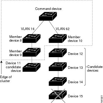
Discovery Through CDP Hops
By using CDP, a cluster command switch can discover switches up to seven CDP hops away (the default is three hops) from the edge of the cluster. The edge of the cluster is where the last cluster member switches are connected to the cluster and to candidate switches. For example, cluster member switches 9 and 10 in Figure 7 are at the edge of the cluster.
In Figure 7, the cluster command switch has ports assigned to VLANs 16 and 62. The CDP hop count is three. The cluster command switch discovers switches 11, 12, 13, and 14 because they are within three hops from the edge of the cluster. It does not discover switch 15 because it is four hops from the edge of the cluster.
Figure 7 Discovery Through CDP Hops
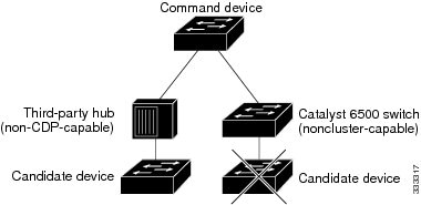
Discovery Through Non-CDP-Capable and Noncluster-Capable Devices
If a cluster command switch is connected to a non-CDP-capable third-party hub (such as a non-Cisco hub), it can discover cluster-enabled devices connected to that third-party hub. However, if the cluster command switch is connected to a noncluster-capable Cisco device, it cannot discover a cluster-enabled device connected beyond the noncluster-capable Cisco device.
Figure 8 shows that the cluster command switch discovers the switch that is connected to a third-party hub. However, the cluster command switch does not discover the switch that is connected to a Catalyst 5000 switch.
Figure 8 Discovery Through Non-CDP-Capable and Noncluster-Capable Devices
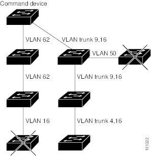
Discovery Through Different VLANs
If the cluster command switch is a Catalyst 2970, Catalyst 3550, Catalyst 3560, or Catalyst 3750 switch, the cluster can have cluster member switches in different VLANs. As cluster member switches, they must be connected through at least one VLAN in common with the cluster command switch. The cluster command switch in Figure 9 has ports assigned to VLANs 9, 16, and 62 and therefore discovers the switches in those VLANs. It does not discover the switch in VLAN 50. It also does not discover the switch in VLAN 16 in the first column because the cluster command switch has no VLAN connectivity to it.
Catalyst 2900 XL, Catalyst 2950, and Catalyst 3500 XL cluster member switches must be connected to the cluster command switch through their management VLAN. For information about discovery through management VLANs, see Discovery Through Different Management VLANs.
Figure 9 Discovery Through Different VLANs
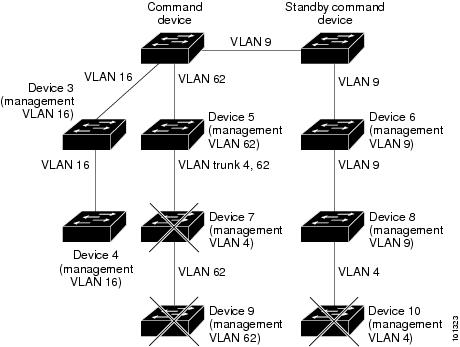
Discovery Through Different Management VLANs
Catalyst 2970, Catalyst 3550, Catalyst 3560, or Catalyst 3750 cluster command switches can discover and manage cluster member switches in different VLANs and different management VLANs. As cluster member switches, they must be connected through at least one VLAN in common with the cluster command switch. They do not need to be connected to the cluster command switch through their management VLAN. The default management VLAN is VLAN 1.
Note: If the switch cluster has a Catalyst 3750 or 2975 switch or has a switch stack, that switch or switch stack must be the cluster command switch.
The cluster command switch and standby command switch in Figure 11 (assuming they are Catalyst 2960, Catalyst 2970, Catalyst 2975, Catalyst 3550, Catalyst 3560, or Catalyst 3750 cluster command switches) have ports assigned to VLANs 9, 16, and 62. The management VLAN on the cluster command switch is VLAN 9. Each cluster command switch discovers the switches in the different management VLANs except these:
■![]() Switches 7 and 10 (switches in management VLAN 4) because they are not connected through a common VLAN (meaning VLANs 62 and 9) with the cluster command switch
Switches 7 and 10 (switches in management VLAN 4) because they are not connected through a common VLAN (meaning VLANs 62 and 9) with the cluster command switch
■![]() Switch 9 because automatic discovery does not extend beyond a noncandidate device, which is switch 7
Switch 9 because automatic discovery does not extend beyond a noncandidate device, which is switch 7
Discovery Through Routed Ports
Note: The LAN Base image supports static routing.
If the cluster command switch has a routed port (RP) configured, it discovers only candidate and cluster member switches in the same VLAN as the routed port.
The Layer 3 cluster command switch in Figure 10 can discover the switches in VLANs 9 and 62 but not the switch in VLAN 4. If the routed port path between the cluster command switch and cluster member switch 7 is lost, connectivity with cluster member switch 7 is maintained because of the redundant path through VLAN 9.
Figure 10 Discovery Through Routed Ports
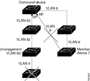
Figure 11 Discovery Through Different Management VLANs with a Layer 3 Cluster Command Switch
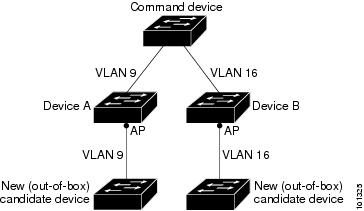
Discovery of Newly Installed Switches
To join a cluster, the new, out-of-the-box switch must be connected to the cluster through one of its access ports. An access port (AP) carries the traffic of and belongs to only one VLAN. By default, the new switch and its access ports are assigned to VLAN 1.
When the new switch joins a cluster, its default VLAN changes to the VLAN of the immediately upstream neighbor. The new switch also configures its access port to belong to the VLAN of the immediately upstream neighbor.
The cluster command switch in Figure 12 belongs to VLANs 9 and 16. When new cluster-capable switches join the cluster:
■![]() One cluster-capable switch and its access port are assigned to VLAN 9.
One cluster-capable switch and its access port are assigned to VLAN 9.
■![]() The other cluster-capable switch and its access port are assigned to management VLAN 16.
The other cluster-capable switch and its access port are assigned to management VLAN 16.
Figure 12 Discovery of Newly Installed Switches
IP Addresses
You must assign IP information to a cluster command switch. You can assign more than one IP address to the cluster command switch, and you can access the cluster through any of the command-switch IP addresses. If you configure a cluster standby group, you must use the standby-group virtual IP address to manage the cluster from the active cluster command switch. Using the virtual IP address ensures that you retain connectivity to the cluster if the active cluster command switch fails and that a standby cluster command switch becomes the active cluster command switch.
If the active cluster command switch fails and the standby cluster command switch takes over, you must either use the standby-group virtual IP address or any of the IP addresses available on the new active cluster command switch to access the cluster.
You can assign an IP address to a cluster-capable switch, but it is not necessary. A cluster member switch is managed and communicates with other cluster member switches through the command-switch IP address. If the cluster member switch leaves the cluster and it does not have its own IP address, you must assign an IP address to manage it as a standalone switch.
For more information about IP addresses, see Performing Switch Setup Configuration
Hostnames
You do not need to assign a hostname to either a cluster command switch or an eligible cluster member. However, a hostname assigned to the cluster command switch can help to identify the switch cluster. The default hostname for the switch is Switch.
If a switch joins a cluster and it does not have a hostname, the cluster command switch appends a unique member number to its own hostname and assigns it sequentially as each switch joins the cluster. The number means the order in which the switch was added to the cluster. For example, a cluster command switch named eng-cluster could name the fifth cluster member eng-cluster-5.
If a switch has a hostname, it retains that name when it joins a cluster and when it leaves the cluster.
If a switch received its hostname from the cluster command switch, was removed from a cluster, was then added to a new cluster, and kept the same member number (such as 5), the switch overwrites the old hostname (such as eng-cluster-5) with the hostname of the cluster command switch in the new cluster (such as mkg-cluster-5). If the switch member number changes in the new cluster (such as 3), the switch retains the previous name ( eng-cluster-5).
Passwords
You do not need to assign passwords to an individual switch if it will be a cluster member. When a switch joins a cluster, it inherits the command-switch password and retains it when it leaves the cluster. If no command-switch password is configured, the cluster member switch inherits a null password. Cluster member switches only inherit the command-switch password.
If you change the member-switch password to be different from the command-switch password and save the change, the switch is not manageable by the cluster command switch until you change the member-switch password to match the command-switch password. Rebooting the member switch does not revert the password back to the command-switch password. We recommend that you do not change the member-switch password after it joins a cluster.
For more information about passwords, see Prevention for Unauthorized Switch Access.
For password considerations specific to the Catalyst 1900 and Catalyst 2820 switches, refer to the installation and configuration guides for those switches.
SNMP Community Strings
A cluster member switch inherits the command-switch first read-only (RO) and read-write (RW) community strings with @esN appended to the community strings:
■![]() command-switch-readonly-community-string @ esN, where N is the member-switch number.
command-switch-readonly-community-string @ esN, where N is the member-switch number.
■![]() command-switch-readwrite-community-string @ esN, where N is the member-switch number.
command-switch-readwrite-community-string @ esN, where N is the member-switch number.
If the cluster command switch has multiple read-only or read-write community strings, only the first read-only and read-write strings are propagated to the cluster member switch.
The switches support an unlimited number of community strings and string lengths. For more information about SNMP and community strings, see Configuring SNMP
For SNMP considerations specific to the Catalyst 1900 and Catalyst 2820 switches, refer to the installation and configuration guides specific to those switches.
TACACS+ and RADIUS
If TACACS+ is configured on a cluster member, it must be configured on all cluster members. Similarly, if RADIUS is configured on a cluster member, it must be configured on all cluster members.The same switch cluster cannot have some members configured with TACACS+ and other members configured with RADIUS.
For more information about TACACS+, see Switch Access with TACACS+. For more information about RADIUS, see Configuring Radius Server Communication.
LRE Profiles
A configuration conflict occurs if a switch cluster has Long-Reach Ethernet (LRE) switches that use both private and public profiles. If one LRE switch in a cluster is assigned a public profile, all LRE switches in that cluster must have that same public profile. Before you add an LRE switch to a cluster, make sure that you assign it the same public profile used by other LRE switches in the cluster.
A cluster can have a mix of LRE switches that use different private profiles.
Managing Switch Clusters
Using the CLI to Manage Switch Clusters
You can configure cluster member switches from the CLI by first logging into the cluster command switch. Enter the rcommand user EXEC command and the cluster member switch number to start a Telnet session (through a console or Telnet connection) and to access the cluster member switch CLI. The command mode changes, and the Cisco IOS commands operate as usual. Enter the exit privileged EXEC command on the cluster member switch to return to the command-switch CLI.
This example shows how to log into member-switch 3 from the command-switch CLI:
If you do not know the member-switch number, enter the show cluster members privileged EXEC command on the cluster command switch.
The Telnet session accesses the member-switch CLI at the same privilege level as on the cluster command switch. The Cisco IOS commands then operate as usual.
Catalyst 1900 and Catalyst 2820 CLI Considerations
If your switch cluster has Catalyst 1900 and Catalyst 2820 switches running standard edition software, the Telnet session accesses the management console (a menu-driven interface) if the cluster command switch is at privilege level 15. If the cluster command switch is at privilege level 1 to 14, you are prompted for the password to access the menu console.
Command-switch privilege levels map to the Catalyst 1900 and Catalyst 2820 cluster member switches running standard and Enterprise Edition Software as follows:
■![]() If the command-switch privilege level is 1 to 14, the cluster member switch is accessed at privilege level 1.
If the command-switch privilege level is 1 to 14, the cluster member switch is accessed at privilege level 1.
■![]() If the command-switch privilege level is 15, the cluster member switch is accessed at privilege level 15.
If the command-switch privilege level is 15, the cluster member switch is accessed at privilege level 15.
Note: The Catalyst 1900 and Catalyst 2820 CLI is available only on switches running Enterprise Edition Software.
For more information about the Catalyst 1900 and Catalyst 2820 switches, refer to the installation and configuration guides for those switches.
Using SNMP to Manage Switch Clusters
When you first power on the switch, SNMP is enabled if you enter the IP information by using the setup program and accept its proposed configuration.
When you create a cluster, the cluster command switch manages the exchange of messages between cluster member switches and an SNMP application. The cluster software on the cluster command switch appends the cluster member switch number ( @esN, where N is the switch number) to the first configured read-write and read-only community strings on the cluster command switch and propagates them to the cluster member switch. The cluster command switch uses this community string to control the forwarding of gets, sets, and get-next messages between the SNMP management station and the cluster member switches.
Note: When a cluster standby group is configured, the cluster command switch can change without your knowledge. Use the first read-write and read-only community strings to communicate with the cluster command switch if there is a cluster standby group configured for the cluster.
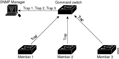
If the cluster member switch does not have an IP address, the cluster command switch redirects traps from the cluster member switch to the management station, as shown in Figure 13. If a cluster member switch has its own IP address and community strings, the cluster member switch can send traps directly to the management station, without going through the cluster command switch.
If a cluster member switch has its own IP address and community strings, they can be used in addition to the access provided by the cluster command switch.
Figure 13 SNMP Management for a Cluster
Additional References
The following sections provide references related to switch administration:
Related Documents
|
|
|
|---|---|
Standards
|
|
|
|---|---|
No new or modified standards are supported by this feature, and support for existing standards has not been modified by this feature. |
MIBs
|
|
|
|---|---|
To locate and download MIBs using Cisco IOS XR software, use the Cisco MIB Locator found at the following URL and choose a platform under the Cisco Access Products menu: http://cisco.com/public/sw-center/netmgmt/cmtk/mibs.shtml |
RFCs
|
|
|
|---|---|
No new or modified RFCs are supported by this feature, and support for existing RFCs has not been modified by this feature. |
 Feedback