- Preface
- Software Licensing
- The Cisco IOS command-line interface (CLI)
- Configuring Interfaces
- Switch Alarms
- Initial Switch Configuration (IP address assignments and DHCP autoconfiguration)
- How to Setup and Use the Cisco Configuration Engine
- How to Create and Manage Switch Clusters
- Performing Switch Administration
- Configuring Precision Time Protocol (PTP)
- Configuring PROFINET
- Common Industrial Protocol (CIP)
- Configuring SDM Templates
- Configuring Switch-Based Authentication
- Configuring IEEE 802.1x Port-Based Authentication
- MACsec
- Web-Based Authentication
- Configuring Smartports Macros
- Configuring SGACL Monitor Mode and SGACL Logging
- Configuring SGT Exchange Protocol over TCP (SXP) and Layer 3 Transport
- Configuring VLANs
- VLAN Trunking Protocol (VTP)
- Configuring Voice VLAN
- How to Configure Spanning Tree Protocol (STP)
- Configuring MSTP
- Configuring Optional Spanning-Tree Features
- Configuring Resilient Ethernet Protocol
- Configuring the FlexLinks and the MAC Address-Table Move Update
- Configuring DHCP
- Dynamic Address Resolution Protocol (ARP)
- Configuring IP Source Guard
- How to Configure Internet Group Management Protocol (IGMP) and Multicast VLAN Registration (MVR)
- Configuring Port-Based Traffic Control
- Configuring LLDP, LLDP-MED, and Wired Location Service
- Configuring SPAN and RSPAN
- One-to-one (1:1) Layer 2 Network Address Translation (NAT)
- How to Configure CDP
- Configuring UniDirectional Link Detection (UDLD)
- Configuring RMON
- Configuring System Message Logging
- Configuring Simple Network Management Protocol (SNMP)
- Network Security with ACLs
- Configuring Quality of Service (QoS)
- Configuring Static IP Unicast Routing
- Configuring IPv6 Host Functions
- Configuring Link State Tracking
- Configuring IP multicast routing
- Configuring Multicast Source Discovery Protocol (MSDP)
- Configuring Multicast Listener Discovery (MLD) snooping
- Configuring HSRP and VRRP
- Configuring IPv6 access control lists (ACLs)
- Configuring Embedded Event Manager (EEM)
- IP Unicast Routing
- IPv6 Unicast Routing
- Unicast Routing Overview
- Configuring Cisco IOS IP SLAs Operations
- Configuring Dying-Gasp
- How to Configure Enhanced Object Tracking
- Configuring MODBUS TCP
- Configuring Ethernet CFM
- Working with the Flash File System
- How to Configure EtherChannels
- Troubleshooting
- How to use a Secure Digital (SD) flash memory module (SD card)
- Restrictions for Performing Switch Setup Configuration
- Information About Performing Switch Setup Configuration
- Switch Bo ot Process
- Default Switch Boot Settings
- Switch Boot Optimization
- Sw itch Information Assignment
- Switch Default Settings
- DHCP-Based Autoconfiguration Overview
- DHCP-Based Autoconfiguration and Image Update
- DHCP Server Configuration Guidelines
- TFTP Server
- DNS Server
- Relay Device
- How to Obtain Configuration Files
- How to Control Environment Variables
- Scheduled Reload of the Software Image
- How to Perform Switch Setup Configuration
Performing Switch Setup Configuration
Restrictions for Performing Switch Setup Configuration
■![]() The DHCP-based autoconfiguration with a saved configuration process stops if there is not at least one Layer 3 interface in an up state without an assigned IP address in the network.
The DHCP-based autoconfiguration with a saved configuration process stops if there is not at least one Layer 3 interface in an up state without an assigned IP address in the network.
■![]() Unless you configure a timeout, the DHCP-based autoconfiguration with a saved configuration feature tries indefinitely to download an IP address.
Unless you configure a timeout, the DHCP-based autoconfiguration with a saved configuration feature tries indefinitely to download an IP address.
■![]() The auto-install process stops if a configuration file cannot be downloaded or it the configuration file is corrupted.
The auto-install process stops if a configuration file cannot be downloaded or it the configuration file is corrupted.
Note: The configuration file that is downloaded from TFTP is merged with the existing configuration in the running configuration but is not saved in the NVRAM unless you enter the write memory or copy running-configuration startup-configuration privileged EXEC command. Note that if the downloaded configuration is saved to the startup configuration, the feature is not triggered during subsequent system restarts.
Information About Performing Switch Setup Configuration
This chapter describes how to perform your initial switch configuration tasks that include IP address assignments and DHCP autoconfiguration.
Switch Boot Process
To start your switch, you need to follow the procedures in the Hardware Installation Guide Hardware Technical Guide for installing and powering on the switch and for setting up the initial switch configuration (IP address, subnet mask, default gateway, secret and Telnet passwords, and so forth).
The normal boot process involves the operation of the boot loader software, which performs these activities:
■![]() Performs low-level CPU initialization—Initializes the CPU registers, which control where physical memory is mapped, its quantity and its speed.
Performs low-level CPU initialization—Initializes the CPU registers, which control where physical memory is mapped, its quantity and its speed.
■![]() Performs power-on self-test (POST) for the CPU subsystem—Tests the CPU DRAM and the portion of the flash device that makes up the flash file system.
Performs power-on self-test (POST) for the CPU subsystem—Tests the CPU DRAM and the portion of the flash device that makes up the flash file system.
■![]() Initializes the flash memory card file system on the system board.
Initializes the flash memory card file system on the system board.
■![]() Loads a default operating system software image into memory and boots up the switch.
Loads a default operating system software image into memory and boots up the switch.
The boot loader provides access to the flash file system before the operating system is loaded. Normally, the boot loader is used only to load, uncompress, and launch the operating system. After the boot loader gives the operating system control of the CPU, the boot loader is not active until the next system reset or power-on.
The switch supports a flash memory card that makes it possible to replace a failed switch without reconfiguring the new switch. The slot for the flash memory card is hot swappable and front-accessed. A cover protects the flash card and holds the card firmly in place. The cover is hinged and closed with a captive screw, which prevents the card from coming loose and protects against shock and vibration.
Use the show flash: privileged EXEC command to display the flash memory card file settings. For information about how to remove or replace the flash memory card on the switch, see the Hardware Installation Guide.
The boot loader also provides trap-door access into the system if the operating system has problems serious enough that it cannot be used. The trap-door mechanism provides enough access to the system so that if it is necessary, you can format the flash file system, reinstall the operating system software image by using the Xmodem Protocol, recover from a lost or forgotten password, and finally restart the operating system.
Note: You can disable password recovery.
Before you can assign switch information, make sure you have connected a PC or terminal to the console port, and configured the PC or terminal-emulation software baud rate and character format to match these of the switch console port:
If the data bits option is set to 8, set the parity option to none.
Default Switch Boot Settings
Switch Boot Optimization
The normal switch boot process involves a memory test, file system check (FSCK), and power-on self-test (POST).
The boot fast command in global configuration mode is enabled by default to permit switch boot optimization, which disables these tests and minimizes the bootup time. However, after a system crash this feature is automatically disabled.
Note - With boot fast enabled, the expected boot time for the switch is from 2 to 3 minutes, depending on image and configuration size.
Reload sequences occur immediately if your switch is set up to automatically bring up the system by using information in the BOOT environment variable. Otherwise, these reload sequences occur after you enter the manual boot command in bootloader configuration mode.
The switch disables the boot fast feature and displays the following warning message:
After the system message appears, the system saves the crash information and automatically resets itself for the next reload cycle.
The boot loader performs its normal full memory test and FSCK check with LED status progress. If the memory and FSCK tests are successful, the system performs additional POST tests and the results are displayed on the console.
The boot fast feature is reenabled after the system comes up successfully.
Switch Information Assignment
You can assign IP information through the switch setup program, through a DHCP server, or manually.
Use the switch setup program if you want to be prompted for specific IP information. With this program, you can also configure a hostname and an enable secret password. The program gives you the option of assigning a Telnet password (to provide security during remote management) and configuring your switch as a command or member switch of a cluster or as a standalone switch. For more information about the setup program, see the Hardware Installation Guide Hardware Technical Guide.
Use a DHCP server for centralized control and automatic assignment of IP information after the server is configured.
Note: If you are using DHCP, do not respond to any of the questions in the setup program until the switch receives the dynamically assigned IP address and reads the configuration file.
If you are an experienced user familiar with the switch configuration steps, manually configure the switch. Otherwise, use the setup program.
Switch Default Settings
|
|
|
|---|---|
DHCP-Based Autoconfiguration Overview
DHCP provides configuration information to Internet hosts and internetworking devices. This protocol consists of two components: one for delivering configuration parameters from a DHCP server to a device and a mechanism for allocating network addresses to devices. DHCP is built on a client-server model, in which designated DHCP servers allocate network addresses and deliver configuration parameters to dynamically configured devices. The switch can act as both a DHCP client and a DHCP server.
During DHCP-based autoconfiguration, your switch (DHCP client) is automatically configured at startup with IP address information and a configuration file.
With DHCP-based autoconfiguration, no DHCP client-side configuration is needed on your switch. However, you need to configure the DHCP server for various lease options associated with IP addresses. If you are using DHCP to relay the configuration file location on the network, you might also need to configure a Trivial File Transfer Protocol (TFTP) server and a Domain Name System (DNS) server.
The DHCP server for your switch can be on the same LAN or on a different LAN than the switch. If the DHCP server is running on a different LAN, you should configure a DHCP relay device between your switch and the DHCP server. A relay device forwards broadcast traffic between two directly connected LANs. A router does not forward broadcast packets, but it forwards packets based on the destination IP address in the received packet.
DHCP-based autoconfiguration replaces the BOOTP client functionality on your switch.
DHCP Client Request Process
When you boot up your switch, the DHCP client is invoked and requests configuration information from a DHCP server when the configuration file is not present on the switch. If the configuration file is present and the configuration includes the ip address dhcp interface configuration command on specific routed interfaces, the DHCP client is invoked and requests the IP address information for those interfaces.
Figure 2 shows the sequence of messages that are exchanged between the DHCP client and the DHCP server.
Figure 2 DHCP Client and Server Message Exchange
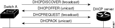
The client, Switch A, broadcasts a DHCPDISCOVER message to locate a DHCP server. The DHCP server offers configuration parameters (such as an IP address, subnet mask, gateway IP address, DNS IP address, a lease for the IP address, and so forth) to the client in a DHCPOFFER unicast message.
In a DHCPREQUEST broadcast message, the client returns a formal request for the offered configuration information to the DHCP server. The formal request is broadcast so that all other DHCP servers that received the DHCPDISCOVER broadcast message from the client can reclaim the IP addresses that they offered to the client.
The DHCP server confirms that the IP address has been allocated to the client by returning a DHCPACK unicast message to the client. With this message, the client and server are bound, and the client uses configuration information received from the server. The amount of information the switch receives depends on how you configure the DHCP serverd in conjunction with the TFTP server. For more information, see TFTP Server.
If the configuration parameters sent to the client in the DHCPOFFER unicast message are invalid (a configuration error exists), the client returns a DHCPDECLINE broadcast message to the DHCP server.
The DHCP server sends the client a DHCPNAK denial broadcast message, which means that the offered configuration parameters have not been assigned, that an error has occurred during the negotiation of the parameters, or that the client has been slow in responding to the DHCPOFFER message. (The DHCP server assigned the parameters to another client.)
A DHCP client might receive offers from multiple DHCP or BOOTP servers and can accept any of the offers; however, the client usually accepts the first offer it receives. The offer from the DHCP server is not a guarantee that the IP address is allocated to the switch. However, the server usually reserves the address until the client has had a chance to formally request the address. If the switch accepts replies from a BOOTP server and configures itself, the switch broadcasts, instead of unicasts, TFTP requests to obtain the switch configuration file.
The DHCP hostname option allows a group of switches to obtain hostnames and a standard configuration from the central management DHCP server. A client (switch) includes in its DCHPDISCOVER message an option 12 field used to request a hostname and other configuration parameters from the DHCP server. The configuration files on all clients are identical except for their DHCP-obtained hostnames.
If a client has a default hostname (the hostname name global configuration command is not configured or the no hostname global configuration command is entered to remove the hostname), the DHCP hostname option is not included in the packet when you enter the ip address dhcp interface configuration command. In this case, if the client receives the DCHP hostname option from the DHCP interaction while acquiring an IP address for an interface, the client accepts the DHCP hostname option and sets the flag to show that the system now has a hostname configured.
DHCP-Based Autoconfiguration and Image Update
You can use the DHCP image upgrade features to configure a DHCP server to download both a new image and a new configuration file to one or more switches in a network. This helps ensure that each new switch added to a network receives the same image and configuration.
There are two types of DHCP image upgrades: DHCP autoconfiguration and DHCP auto-image update.
DHCP Autoconfiguration
DHCP autoconfiguration downloads a configuration file to one or more switches in your network from a DHCP server. The downloaded configuration file becomes the running configuration of the switch. It does not over write the bootup configuration saved in the flash, until you reload the switch.
DHCP Auto-Image Update
You can use DHCP auto-image upgrade with DHCP autoconfiguration to download both a configuration and a new image to one or more switches in your network. The switch (or switches) downloading the new configuration and the new image can be blank (or only have a default factory configuration loaded).
If the new configuration is downloaded to a switch that already has a configuration, the downloaded configuration is appended to the configuration file stored on the switch. (Any existing configuration is not overwritten by the downloaded one.)
Note: To enable a DHCP auto-image update on the switch, the TFTP server where the image and configuration files are located must be configured with the correct option 67 (the configuration filename), option 66 (the DHCP server hostname) option 150 (the TFTP server address), and option 125 (description of the file) settings.
For procedures to configure the switch as a DHCP server, see DHCP Server Configuration Guidelines and the “Configuring DHCP” section of the “IP addressing and Services” section of the Cisco IOS IP DHCP Configuration Guide, Release 15.0.
After you install the switch in your network, the auto-image update feature starts. The downloaded configuration file is saved in the running configuration of the switch, and the new image is downloaded and installed on the switch. When you reboot the switch, the configuration is stored in the saved configuration on the switch.
DHCP Server Configuration Guidelines
Follow these guidelines if you are configuring a device as a DHCP server:
■![]() Configure the DHCP server with reserved leases that are bound to each switch by the switch hardware address.
Configure the DHCP server with reserved leases that are bound to each switch by the switch hardware address.
■![]() If you want the switch to receive IP address information, you must configure the DHCP server with these lease options:
If you want the switch to receive IP address information, you must configure the DHCP server with these lease options:
–![]() IP address of the client (required)
IP address of the client (required)
–![]() Subnet mask of the client (required)
Subnet mask of the client (required)
–![]() Router IP address (default gateway address to be used by the switch) (required)
Router IP address (default gateway address to be used by the switch) (required)
–![]() DNS server IP address (optional)
DNS server IP address (optional)
■![]() If you want the switch to receive the configuration file from a TFTP server, you must configure the DHCP server with these lease options:
If you want the switch to receive the configuration file from a TFTP server, you must configure the DHCP server with these lease options:
–![]() Boot filename (the name of the configuration file that the client needs) (recommended)
Boot filename (the name of the configuration file that the client needs) (recommended)
■![]() Depending on the settings of the DHCP server, the switch can receive IP address information, the configuration file, or both.
Depending on the settings of the DHCP server, the switch can receive IP address information, the configuration file, or both.
■![]() If you do not configure the DHCP server with the lease options described previously, it replies to client requests with only those parameters that are configured.
If you do not configure the DHCP server with the lease options described previously, it replies to client requests with only those parameters that are configured.
If the IP address and the subnet mask are not in the reply, the switch is not configured. If the router IP address or the TFTP server name are not found, the switch might send broadcast, instead of unicast, TFTP requests. Unavailability of other lease options does not affect autoconfiguration.
■![]() The switch can act as a DHCP server. By default, the Cisco IOS DHCP server and relay agent features are enabled on your switch but are not configured. These features are not operational. If your DHCP server is a Cisco device, for additional information about configuring DHCP, see the “Configuring DHCP” section of the “IP Addressing and Services” section of the Cisco IOS IP Configuration Guide on Cisco.com.
The switch can act as a DHCP server. By default, the Cisco IOS DHCP server and relay agent features are enabled on your switch but are not configured. These features are not operational. If your DHCP server is a Cisco device, for additional information about configuring DHCP, see the “Configuring DHCP” section of the “IP Addressing and Services” section of the Cisco IOS IP Configuration Guide on Cisco.com.
TFTP Server
Based on the DHCP server configuration, the switch attempts to download one or more configuration files from the TFTP server. If you configured the DHCP server to respond to the switch with all the options required for IP connectivity to the TFTP server, and if you configured the DHCP server with a TFTP server name, address, and configuration filename, the switch attempts to download the specified configuration file from the specified TFTP server.
If you did not specify the configuration filename, the TFTP server, or if the configuration file could not be downloaded, the switch attempts to download a configuration file by using various combinations of filenames and TFTP server addresses. The files include the specified configuration filename (if any) and these files: network-config, cisconet.cfg, and hostname.config (or hostname.cfg), where hostname is the switch’s current hostname. The TFTP server addresses used include the specified TFTP server address (if any) and the broadcast address (255.255.255.255).
For the switch to successfully download a configuration file, the TFTP server must contain one or more configuration files in its base directory. The files can include these files:
■![]() The configuration file named in the DHCP reply (the actual switch configuration file).
The configuration file named in the DHCP reply (the actual switch configuration file).
■![]() The network-confg or the cisconet.cfg file (known as the default configuration files).
The network-confg or the cisconet.cfg file (known as the default configuration files).
■![]() The router-confg or the ciscortr.cfg file (These files contain commands common to all switches. Normally, if the DHCP and TFTP servers are properly configured, these files are not accessed.)
The router-confg or the ciscortr.cfg file (These files contain commands common to all switches. Normally, if the DHCP and TFTP servers are properly configured, these files are not accessed.)
If you specify the TFTP server name in the DHCP server-lease database, you must also configure the TFTP server name-to-IP-address mapping in the DNS-server database.
If the TFTP server to be used is on a different LAN from the switch, or if it is to be accessed by the switch through the broadcast address (which occurs if the DHCP server response does not contain all the required information described previously), a relay must be configured to forward the TFTP packets to the TFTP server. For more information, see Relay Device. The preferred solution is to configure the DHCP server with all the required information.
DNS Server
The DHCP server uses the DNS server to resolve the TFTP server name to an IP address. You must configure the TFTP server name-to-IP address map on the DNS server. The TFTP server contains the configuration files for the switch.
You can configure the IP addresses of the DNS servers in the lease database of the DHCP server from where the DHCP replies will retrieve them. You can enter up to two DNS server IP addresses in the lease database.
The DNS server can be on the same or on a different LAN as the switch. If it is on a different LAN, the switch must be able to access it through a router.
Relay Device
You must configure a relay device, also referred to as a relay agent, when a switch sends broadcast packets that require a response from a host on a different LAN. Examples of broadcast packets that the switch might send are DHCP, DNS, and in some cases, TFTP packets. You must configure this relay device to forward received broadcast packets on an interface to the destination host.
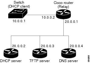
If the relay device is a Cisco router, enable IP routing (ip routing global configuration command), and configure helper addresses by using the ip helper-address interface configuration command.
For example, in Figure 3, configure the router interfaces as follows:
Figure 3 Relay Device Used in Autoconfiguration
How to Obtain Configuration Files
Depending on the availability of the IP address and the configuration filename in the DHCP reserved lease, the switch obtains its configuration information in these ways:
■![]() The IP address and the configuration filename is reserved for the switch and provided in the DHCP reply (one-file read method).
The IP address and the configuration filename is reserved for the switch and provided in the DHCP reply (one-file read method).
The switch receives its IP address, subnet mask, TFTP server address, and the configuration filename from the DHCP server. The switch sends a unicast message to the TFTP server to retrieve the named configuration file from the base directory of the server and upon receipt, it completes its boot-up process.
■![]() The IP address and the configuration filename is reserved for the switch, but the TFTP server address is not provided in the DHCP reply (one-file read method).
The IP address and the configuration filename is reserved for the switch, but the TFTP server address is not provided in the DHCP reply (one-file read method).
The switch receives its IP address, subnet mask, and the configuration filename from the DHCP server. The switch sends a broadcast message to a TFTP server to retrieve the named configuration file from the base directory of the server, and upon receipt, it completes its boot-up process.
■![]() Only the IP address is reserved for the switch and provided in the DHCP reply. The configuration filename is not provided (two-file read method).
Only the IP address is reserved for the switch and provided in the DHCP reply. The configuration filename is not provided (two-file read method).
The switch receives its IP address, subnet mask, and the TFTP server address from the DHCP server. The switch sends a unicast message to the TFTP server to retrieve the network-confg or cisconet.cfg default configuration file. (If the network-confg file cannot be read, the switch reads the cisconet.cfg file.)
The default configuration file contains the hostnames-to-IP-address mapping for the switch. The switch fills its host table with the information in the file and obtains its hostname. If the hostname is not found in the file, the switch uses the hostname in the DHCP reply. If the hostname is not specified in the DHCP reply, the switch uses the default Switch as its hostname.
After obtaining its hostname from the default configuration file or the DHCP reply, the switch reads the configuration file that has the same name as its hostname ( hostname -confg or hostname.cfg, depending on whether network-confg or cisconet.cfg was read earlier) from the TFTP server. If the cisconet.cfg file is read, the filename of the host is truncated to eight characters.
If the switch cannot read the network-confg, cisconet.cfg, or the hostname file, it reads the router-confg file. If the switch cannot read the router-confg file, it reads the ciscortr.cfg file.
Note: The switch broadcasts TFTP server requests if the TFTP server is not obtained from the DHCP replies, if all attempts to read the configuration file through unicast transmissions fail, or if the TFTP server name cannot be resolved to an IP address.
How to Control Environment Variables
With a normally operating switch, you enter the boot loader mode only through a switch console connection configured for 9600 b/s. Unplug the switch power cord, and press the switch Mode button while reconnecting the power cord. You can release the Mode button a second or two after the LED above port 1 turns off. Then the boot loader switch: prompt appears.
The switch boot loader software provides support for nonvolatile environment variables, which can be used to control how the boot loader or any other software running on the system behaves. Boot loader environment variables are similar to environment variables that can be set on UNIX or DOS systems.
Environment variables that have values are stored in flash memory outside of the flash file system.
Each line in these files contains an environment variable name and an equal sign followed by the value of the variable. A variable has no value if it is not listed in this file; it has a value if it is listed in the file even if the value is a null string. A variable that is set to a null string (for example, “ ”) is a variable with a value. Many environment variables are predefined and have default values.
Environment variables store two kinds of data:
■![]() Data that controls code, which does not read the Cisco IOS configuration file. For example, the name of a boot loader helper file, which extends or patches the functionality of the boot loader can be stored as an environment variable.
Data that controls code, which does not read the Cisco IOS configuration file. For example, the name of a boot loader helper file, which extends or patches the functionality of the boot loader can be stored as an environment variable.
■![]() Data that controls code, which is responsible for reading the Cisco IOS configuration file. For example, the name of the Cisco IOS configuration file can be stored as an environment variable.
Data that controls code, which is responsible for reading the Cisco IOS configuration file. For example, the name of the Cisco IOS configuration file can be stored as an environment variable.
You can change the settings of the environment variables by accessing the boot loader or by using Cisco IOS commands. Under normal circumstances, it is not necessary to alter the setting of the environment variables.
Common Environment Variables
Table 14 describes the function of the most common environment variables.
Scheduled Reload of the Software Image
You can schedule a reload of the software image to occur on the switch at a later time (for example, late at night or during the weekend when the switch is used less), or you can synchronize a reload network-wide (for example, to perform a software upgrade on all switches in the network).
Note: A scheduled reload must take place within approximately 24 days.
You have these reload options:
■![]() Software reload to take effect in the specified minutes or hours and minutes. The reload must take place within approximately 24 days. You can specify the reason for the reload in a string up to 255 characters in length.
Software reload to take effect in the specified minutes or hours and minutes. The reload must take place within approximately 24 days. You can specify the reason for the reload in a string up to 255 characters in length.
■![]() Software reload to take place at the specified time (using a 24-hour clock). If you specify the month and day, the reload is scheduled to take place at the specified time and date. If you do not specify the month and day, the reload takes place at the specified time on the current day (if the specified time is later than the current time) or on the next day (if the specified time is earlier than the current time). Specifying 00:00 schedules the reload for midnight.
Software reload to take place at the specified time (using a 24-hour clock). If you specify the month and day, the reload is scheduled to take place at the specified time and date. If you do not specify the month and day, the reload takes place at the specified time on the current day (if the specified time is later than the current time) or on the next day (if the specified time is earlier than the current time). Specifying 00:00 schedules the reload for midnight.
The reload command halts the system. If the system is not set to manually boot up, it reboots itself.
If your switch is configured for manual booting, do not reload it from a virtual terminal. This restriction prevents the switch from entering the boot loader mode and thereby taking it from the remote user’s control.
If you modify your configuration file, the switch prompts you to save the configuration before reloading. During the save operation, the system requests whether you want to proceed with the save if the CONFIG_FILE environment variable points to a startup configuration file that no longer exists. If you proceed in this situation, the system enters setup mode upon reload.
To cancel a previously scheduled reload, use the reload cancel privileged EXEC command.
How to Perform Switch Setup Configuration
Using DHCP to download a new image and a new configuration to a switch requires that you configure at least two switches. One switch acts as a DHCP and TFTP server and the second switch (client) is configured to download either a new configuration file or a new configuration file and a new image file.
Configuring DHCP Autoconfiguration (Only Configuration File)
This task describes how to configure DHCP autoconfiguration of the TFTP and DHCP settings on a new switch to download a new configuration file.
Configuring DHCP Auto-Image Update (Configuration File and Image)
This task describes DHCP autoconfiguration to configure TFTP and DHCP settings on a new switch to download a new image and a new configuration file.
You must create a text file (for example, autoinstall_dhcp) that will be uploaded to the switch. In the text file, put the name of the image that you want to download. This image must be a tar and not a bin file.
Configuring the Client
You should only configure and enable the Layer 3 interface. Do not assign an IP address or DHCP-based autoconfiguration with a saved configuration.
Manually Assigning IP Information on a Routed Port
This task describes how to manually assign IP information on a Layer 3 routed port.
Manually Assigning IP Information to SVIs
This task describes how to manually assign IP information to multiple switched virtual interfaces (SVIs).
Modifying the Startup Configuration
Specifying the Filename to Read and Write the System Configuration
By default, the Cisco IOS software uses the config.text file to read and write a nonvolatile copy of the system configuration. However, you can specify a different filename, which will be loaded during the next boot-up cycle.
Manually Booting the Switch
By default, the switch automatically boots up; however, you can configure it to manually boot up.
Use a standalone switch for this task.
Booting a Specific Software Image
By default, the switch attempts to automatically boot up the system using information in the BOOT environment variable. If this variable is not set, the switch attempts to load and execute the first executable image it can by performing a recursive, depth-first search throughout the flash file system. In a depth-first search of a directory, each encountered subdirectory is completely searched before continuing the search in the original directory. However, you can specify a specific image to boot up.
Monitoring Switch Setup Configuration
Verifying the Switch Running Configuration
You can check the configuration settings that you entered or changes that you made by entering this privileged EXEC command:
To store the configuration or changes you have made to your startup configuration in flash memory, enter this privileged EXEC command:
This command saves the configuration settings that you made. If you fail to do this, your configuration will be lost the next time you reload the system. To display information stored in the NVRAM section of flash memory, use the show startup-config or more startup-config privileged EXEC command.
For more information about alternative locations from which to copy the configuration file, see Working with the Cisco IOS File System, Configuration Files, and Software Images
Configuration Examples for Performing Switch Setup Configuration
Retrieving IP Information Using DHCP-Based Autoconfiguration: Example
Switch A reads its configuration file as follows:
■![]() It obtains its IP address 10.0.0.21 from the DHCP server.
It obtains its IP address 10.0.0.21 from the DHCP server.
■![]() If no configuration filename is given in the DHCP server reply, Switch A reads the network-confg file from the base directory of the TFTP server.
If no configuration filename is given in the DHCP server reply, Switch A reads the network-confg file from the base directory of the TFTP server.
■![]() It adds the contents of the network-confg file to its host table.
It adds the contents of the network-confg file to its host table.
■![]() It reads its host table by indexing its IP address 10.0.0.21 to its hostname (switcha).
It reads its host table by indexing its IP address 10.0.0.21 to its hostname (switcha).
■![]() It reads the configuration file that corresponds to its hostname; for example, it reads switch1-confg from the TFTP server.
It reads the configuration file that corresponds to its hostname; for example, it reads switch1-confg from the TFTP server.
Switches B through D retrieve their configuration files and IP addresses in the same way.
Figure 4 shows a sample network for retrieving IP information by using DHCP-based autoconfiguration.
Figure 4 DHCP-Based Autoconfiguration Network Example
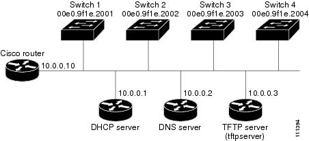
Table 15 shows the configuration of the reserved leases on the DHCP server.
|
|
|
|
|
|
|---|---|---|---|---|
The DNS server maps the TFTP server name tftpserver to IP address 10.0.0.3.
TFTP Server Configuration (on UNIX)
The TFTP server base directory is set to /tftpserver/work/. This directory contains the network-confg file used in the two-file read method. This file contains the hostname to be assigned to the switch based on its IP address. The base directory also contains a configuration file for each switch ( switcha-confg, switchb-confg, and so forth) as shown in this display:
No configuration file is present on Switch A through Switch D.
Scheduling Software Image Reload: Examples
This example shows how to reload the software on the switch on the current day at 7:30 p.m:
This example shows how to reload the software on the switch at a future time:
To cancel a previously scheduled reload, use the reload cancel privileged EXEC command.
Configuring DHCP Auto-Image Update: Example
Configuring a Switch as a DHCP Server: Example
Configuring Client to Download Files from DHCP Server
This example uses a Layer 3 SVI interface on VLAN 99 to enable DHCP-based autoconfiguration with a saved configuration:
Additional References
The following sections provide references related to switch administration:
Standards
|
|
|
|---|---|
No new or modified standards are supported by this feature, and support for existing standards has not been modified by this feature. |
MIBs
|
|
|
|---|---|
To locate and download MIBs using Cisco IOS XR software, use the Cisco MIB Locator found at the following URL and choose a platform under the Cisco Access Products menu: http://cisco.com/public/sw-center/netmgmt/cmtk/mibs.shtml |
RFCs
|
|
|
|---|---|
No new or modified RFCs are supported by this feature, and support for existing RFCs has not been modified by this feature. |
 Feedback