About 650W AC Alternate PSU on C9500
An alternate 650W AC Power Supply Unit (PSU) which has similar specification as the existing C9K-PWR-650WAC-R has been developed for Cisco Catalyst 9500 Series Switches. This alternate PSU has been fully tested and qualified with Cisco Catalyst 9500 Series Switches that support 650W AC PSU. This PSU will have the same Product ID (PID) as the existing C9K-PWR-650WAC-R.
Please see below for details of this PSU, including technical specifications and warranty information.
Warranty
This PSU will be covered by the Cisco's standard warranty terms.
Technical Specifications
|
Characteristic |
Specification |
|---|---|
|
AC input voltage |
Nominal range: 100 and 240 VAC (Range: 90-132 VAC, 180-264 VAC) |
|
AC input frequency |
Nominal range: 50 to 60 Hz (Range: 47-63 Hz) |
|
Maximum AC input current |
7.6 A at 90 - 132 VAC, 3.65 A at 180 - 264 VAC |
|
Maximum input volt Amperes |
760 VA at 100 VAC |
|
Maximum output power per power supply |
650 W |
|
Maximum in-rush current |
11 A (sub-cycle duration) |
|
Maximum hold-up time |
12 ms at 650 W |
|
Power supply output voltage |
12 VDC |
|
Power supply standby voltage |
12 VDC |
|
Efficiency rating |
Climate Savers Platinum Efficiency (80Plus Platinum certified) |
|
Form factor |
RSP1 |
Key Differences
|
Criteria |
Original PSU |
Alternate PSU |
|---|---|---|
|
IEC-61000-4-5 surge |
4KV CM, 2KV DM |
2.5KV CM, 1KV DM |
|
AC line hold-up time |
>=20ms@90% load |
>=12ms@100% load |
|
OPP (Over Power Protection) |
130% x rated load |
140% x rated load |
|
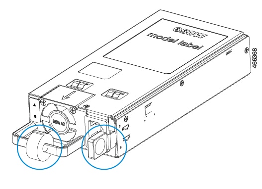
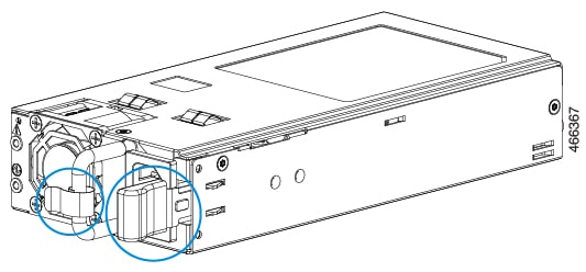
Handle/latch |
 |
 |
|
Color |
Handle/latch: CISCO MEDIUM GRAY |
Handle: BLACK Latch: CISCO BURGUNDY |
Installing or Replacing an AC Power Supply
Procedure
|
Step 1 |
Turn off the power at its source. |
||
|
Step 2 |
Release the power cord from velcro strap. |
||
|
Step 3 |
Remove the power cord from the power connector. |
||
|
Step 4 |
Press the release latch at the right side of the power supply module inward and slide the power supply out.
|
||
|
Step 5 |
Insert the new power supply into the power-supply slot, and gently push it into the slot. When inserted correctly, the 650 W power supply is flush with the switch rear panel. 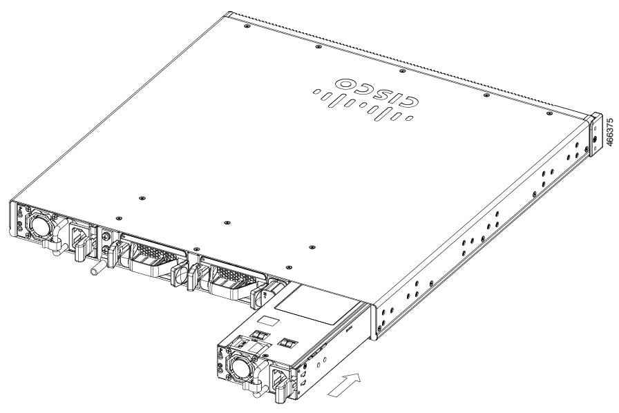 |
||
|
Step 6 |
Connect the power cord to the power supply and to an AC power outlet. |
||
|
Step 7 |
(Optional) Secure the power cord to the power supply using the velcro strap. 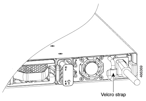 |
||
|
Step 8 |
Turn on the power at the power source. |
||
|
Step 9 |
Verify that the power status LED is green. |
Contact Cisco
If you have questions or feedback about this C9500 alternate PSU, please send your inquiries directly to C9K-PSU@external.cisco.com.
 Feedback