Update ASA connection credentials in Security Cloud Control Firewall Management
In the process of onboarding an ASA, you entered the username and password Security Cloud Control Firewall Management must use to connect to the device. If those credentials are changed on the device, use the Update Credentials device action to update those credentials on Security Cloud Control Firewall Management as well. This feature allows you to update the credentials on Security Cloud Control Firewall Management without having to re-onboard the device. The username and password combination you switch to must already exist on the ASA or Authentication, Authorization, and Accounting (AAA) server for that user. This process only affects the Security Cloud Control Firewall Management database; no changes to the ASA configuration are made when using the Update Credentials feature.
Procedure
|
Step 1 |
In the left pane, click . |
||
|
Step 2 |
Click the Devices tab and then click ASA. |
||
|
Step 3 |
Select the ASAs whose connection credentials it is you want to update. You can update the credentials on one or multiple ASAs at once. |
||
|
Step 4 |
In the Device Actions pane, click Update Credentials. |
||
|
Step 5 |
Select the Cloud Connector or the Secure Device Connector (SDC) you use to connect the ASA(s) to Security Cloud Control. |
||
|
Step 6 |
Enter the new username and password you want to use to connect to the ASAs. |
||
|
Step 7 |
After the credentials are changed, Security Cloud Control syncs the device.
|
Move an ASA from one SDC to Another
Procedure
|
Step 1 |
In the left pane, click |
|
Step 2 |
In the left pane, click Inventory. |
|
Step 3 |
Select the ASAs you want to move to the other SDC. |
|
Step 4 |
In the Device Actions pane, click Update Credentials. |
|
Step 5 |
Click the Secure Device Connector button and select the SDC you want to move the device to. |
|
Step 6 |
Enter the administrator username and password you used to onboard the ASA, and click Update. You do not have to deploy these changes to the device. |
 >
>  ) on the corresponding parameter highlights unsaved changes.
 ) highlights parameters that use existing local values from the device.

 , it means that an error has occurred while applying the shared system settings policy to your devices. To troubleshoot the
issue, click the policy on the ASA System Settings page and in the
, it means that an error has occurred while applying the shared system settings policy to your devices. To troubleshoot the
issue, click the policy on the ASA System Settings page and in the  .
.


 .
.
 ) icon in the right pane.
 ) button.
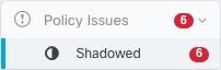
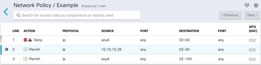
 because it's shadowing another rule in the policy. The rule on line 2 is marked as being shadowed
  by another rule in the policy. The action for the rule on line 2 is grayed-out because it's entirely shadowed by another
rule in the policy.
by another rule in the policy. The action for the rule on line 2 is grayed-out because it's entirely shadowed by another
rule in the policy. 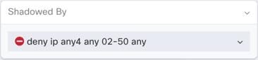

 Feedback