Introduction to objects
An object is a reusable container of information that you can use in one or more security policies. Objects help you maintain policy consistency because you can define a value once, use it in multiple policies, and update every policy that uses the object by changing the object.
When you onboard a device, Security Cloud Control Firewall Management recognizes all the objects used by that device, saves them, and lists them on the Objects page. From the Objects page, you can edit existing objects and create new ones to use in your security policies.
Security Cloud Control Firewall
Management calls an object used on multiple devices a shared object and identifies them in the Objects page with this badge  .
.
You can use Security Cloud Control Firewall Management to manage objects in these ways:
-
Search for and filter all your objects based on a variety of criteria.
-
Find duplicate, unused, and inconsistent objects, and then consolidate, delete, resolve, ignore, or unignore object issues.
-
Find and delete unassociated objects if they are not needed.
-
Discover objects that are shared across devices.
-
Evaluate which policies and devices are affected before you commit an object change.
-
Compare a set of objects and their relationships with different policies and devices.
-
Capture objects that are in use after a device is onboarded to Security Cloud Control Firewall Management.
Sometimes a shared object develops some "issue" and is no longer perfectly shared across multiple policies or devices:
-
Duplicate objects: Two or more objects on the same device have different names but the same values. These objects usually serve similar purposes and are used by different policies. Duplicate objects are identified by this issue icon:

-
Inconsistent objects: Two or more devices have objects with the same name but different values. This issue can occur when objects start with the same name and content but later diverge. Inconsistent objects are identified by this issue icon:

-
Unused objects: An object exists in a device configuration but is not referenced by another object, an access list, or a NAT rule. Unused objects are identified by this issue icon:

You can also create objects for immediate use in rules or policies. You can create an object that is unassociated with any rule or policy. When you use that unassociated object in a rule or policy, Security Cloud Control Firewall Management creates a copy of it and uses the copy.
You can view the objects managed by Security Cloud Control Firewall Management by navigating to the Objects menu or by viewing them in the details of a network policy.
If you have issues with creating, editing, or reading objects from an onboarded device, see Troubleshoot Security Cloud Control for more information.
Supported object types
The object types that you can create and manage depend on the managed device type.
Common object types
|
Object Type |
Description |
|---|---|
|
Network groups and network objects (collectively referred to as network objects) define the addresses of hosts or networks. |
|
|
Use URL objects and groups (collectively referred to as URL objects) to define the URL or IP addresses of web requests. You can use these objects to implement manual URL filtering in access control policies or blocking in Security Intelligence policies. |
ASA object types
|
Object |
Description |
|---|---|
|
Matches an individual IPv4 or IPv6 address or an IP address range. |
|
|
Represents files used in configurations, typically for remote access VPN policies. These objects can contain AnyConnect Client Profile and AnyConnect Client Image files. |
|
|
Defines host or network addresses. This category includes network objects and network groups. |
|
|
Defines protocols or ports that are part of the TCP/IP protocol suite. This category includes service objects, service groups, and port groups. |
|
|
Defines a start time, an end time, and optional recurring entries for time-based access to features or assets. |
|
|
Manages and tracks digital certificates in ASA. |
FDM-managed device object types
|
Object |
Description |
|---|---|
|
Represents files used in configurations, typically for remote access VPN policies. These objects can contain AnyConnect Client Profile and AnyConnect Client Image files. |
|
|
Provides digital identification for authentication. Certificates are used for SSL, TLS, and DTLS connections, such as HTTPS and LDAPS. |
|
|
Defines DNS servers that resolve fully qualified domain names (FQDNs), such as www.example.com, to IP addresses. You can configure different DNS group objects for management and data interfaces. |
|
|
Defines countries and continents that host the source or destination of traffic. You can use geolocation objects in policies instead of IP addresses. |
|
|
Contains the parameters required for IKEv1 policies when defining VPN connections. |
|
|
IKEv2 Policy |
Contains the parameters required for IKEv2 policies when defining VPN connections. |
|
IKEv1 IPSEC Proposal |
IPsec Proposal objects configure the IPsec proposal used during IKE Phase 1 negotiations. The IPsec proposal defines the combination of security protocols and algorithms that secure traffic in an IPsec tunnel. |
|
IKEv2 IPSEC Proposal |
IPsec Proposal objects configure the IPsec proposal used during IKE Phase 2 negotiations. The IPsec proposal defines the combination of security protocols and algorithms that secure traffic in an IPsec tunnel. |
|
Defines host or network addresses. This category includes network objects and network groups. |
|
|
Groups interfaces into network segments that help classify and manage traffic. |
|
|
Defines protocols or ports that are part of the TCP/IP protocol suite. This category includes service objects, service groups, and port groups. |
|
|
Identifies source or destination addresses based on a security group tag (SGT) assigned by Cisco ISE. |
|
|
Identifies a server that can receive connection-oriented or diagnostic syslog messages. |
|
|
Defines URLs or IP addresses for web requests. URL objects and URL groups can be used for manual URL filtering in access control policies or blocking in Security Intelligence policies. |
On-Premises Firewall Management Center object types
|
Object |
Description |
|---|---|
|
Defines host or network addresses. This category includes network objects and network groups. |
|
|
Defines protocols or ports that are part of the TCP/IP protocol suite. This category includes service objects, service groups, and port groups. |
Shared objects
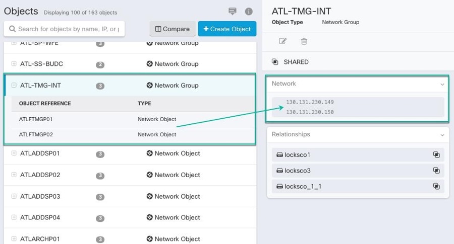
A shared object is an object on multiple devices that has the same name and the same contents. Shared objects help you maintain policies because one object change affects every policy that uses that shared object.
When looking at a shared object, Security Cloud Control shows you the contents of the object in the object table. Shared objects have exactly the same contents. Security Cloud Control shows you a combined or "flattened" view of the elements of the object in the details pane. Notice that in the details pane, the network elements are flattened into a simple list and not directly associated with a named object.
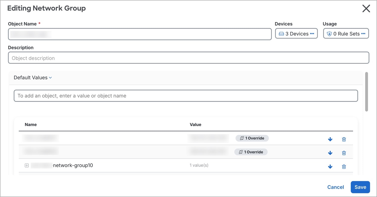
Object Overrides
An object override lets you customize a shared object for specific devices. When a device has an override, Security Cloud Control Firewall Management uses the override value for that device instead of the object's default value.
Overrides allow you to maintain a single shared policy across devices while tailoring individual object values where needed.
Use overrides when you want to maintain one shared policy across devices but need specific devices to use different object values. For example, a shared print-server object can use the default value 10.1.1.100 for most offices, while Office B uses an override value of 10.2.1.100.
Overrides on network object groups
For network object groups, overrides fully replace the default values for the devices that are assigned to the override. A device with an override receives only the override values, not the default values.
This replacement behavior has these effects:
-
Changes to default values affect only devices without overrides.
-
Changes to an override affect only the devices assigned to that override.
-
If a device needs the default values plus a local value, add all required values to the override.
For example, a shared dns-servers network group contains default values primary-dns (10.0.1.53) and secondary-dns (10.0.2.53) for Branch A, Branch B, and Branch C. Branch C also needs local-dns-cache (10.30.1.53). Because a network group override replaces the defaults, the Branch C override must contain primary-dns, secondary-dns, and local-dns-cache.
If you later add a default value, such as tertiary-dns, Branch A and Branch B receive the new default value automatically. Branch C does not receive it until you add tertiary-dns to the Branch C override.
 Note |
Security Cloud Control allows you to override objects associated with the rules in a ruleset. When you add a new object to a rule, you can override it only after you attach a device to the ruleset and save the changes. See Configure Rulesets for an FTD for more information. |
Unassociated objects
An unassociated object is not associated with any rule or policy. When you use an unassociated object in a rule or policy, Security Cloud Control Firewall Management creates and uses a copy of that object. The original unassociated object remains available until a nightly maintenance job deletes it or you delete it manually.
Security Cloud Control Firewall Management keeps unassociated objects as a copy so that configuration data is not lost if the related rule or policy is deleted accidentally.
To view unassociated objects, choose Objects >  , and check Unassociated.
Compare objects
Use object comparison to review up to three objects side by side and inspect their details and relationships.
Procedure
|
Step 1 |
In the left pane, click Objects and choose an option. |
|
Step 2 |
Filter the objects on the page to find the objects you want to compare. |
|
Step 3 |
Click the Compare button |
|
Step 4 |
Select up to three objects. |
|
Step 5 |
Review the objects side-by-side at the bottom of the screen. |
|
Step 6 |
(Optional) In Relationships, select a device name, and then select View Configuration to view the device configuration with the object entry highlighted. |
 .
.
Object filters
Use filters on the Objects page to find objects by device, issue, shared state, association state, object type, or search value. You can also include or exclude system-defined objects.
The object type filter lets you filter by object types such as network object, network group, URL object, URL group, service object, and service group. The shared objects filter lets you filter objects that have default values, override values, or additional values.
You can combine device and object filters to create focused search strategies. For example, you can search for objects that match this logic: Issues is Unused OR Inconsistent, AND Shared Objects has Default Values OR Additional Values, AND Unassociated Objects is selected.
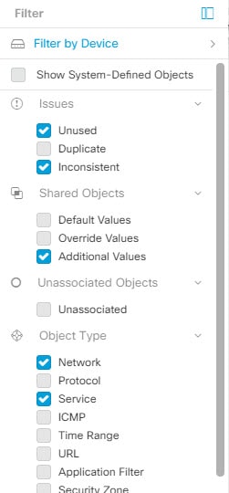
To filter, click in the left-hand pane of the Objects tab:
-
Filter by Device: Shows objects found on selected devices.
-
Show System-Defined Objects: Includes predefined system objects in search and filter results. System objects cannot be edited or deleted. Some devices come with predefined objects for common services. These system objects are convenient because they are already made for you and you can use them in your rules and policies. There can be many system objects in the objects table. System objects cannot be edited or deleted.
-
Issues: Shows unused, duplicate, or inconsistent objects. If you select more than one issue, objects in any selected issue category are included.
-
Ignored Issues: Shows objects whose issues were ignored by an administrator.
-
Shared Objects: Shows shared objects. You can filter by default values, override values, additional values, or a combination.
-
Unassociated Objects: Shows objects that are not associated with any rule or policy.
-
Object Type: Shows selected object types, such as network objects, network groups, URL objects, URL groups, service objects, and service groups.
Within a main filter, subfilters can further narrow the results by object type, such as Network, Service, or Protocol. Filters across categories combine with an AND relationship. Multiple selections within a category can combine with an OR relationship.
For example, a filter set can search for objects that match this logic: objects on selected devices AND inconsistent objects AND network objects or service objects AND object names that contain group.
Configure object filters
You can filter on as few or as many criteria as you want. The more categories you filter by, the fewer results you should expect.
Procedure
|
Step 1 |
In the left pane, click Objects. |
|
Step 2 |
Open the filter panel by clicking the filter icon |
|
Step 3 |
If you want to restrict your results to those found on particular devices:
|
|
Step 4 |
Check Show System Objects to include system objects in your search results. Uncheck Show System Objects to exclude system objects from your search results. |
|
Step 5 |
Check the object Issues you want to filter. If you check more than one issue, objects in any of the categories you check are included in your filter results. |
|
Step 6 |
Check Ignored issues if you want to see the object that had issues but was ignored by the administrator. |
|
Step 7 |
Check the required filter in Shared Objects if you are filtering for objects shared between two or more devices.
|
|
Step 8 |
Check Unassociated if you are filtering for objects that are not part of any rule or policy. |
|
Step 9 |
Check the Object Types you want to filter. |
|
Step 10 |
You can also add an object name, IP address, or port number to the Objects search field to find objects with your search criteria among the filtered results. |
Exclude device filters when you need full relationships
When you filter by device, Security Cloud Control Firewall Management shows objects on that device but does not show the object's relationships to all other devices.
For example, if ObjectA is shared between ASA1 and ASA2, and you filter for shared objects on ASA1, Security Cloud Control Firewall Management shows `ObjectA`, but the Relationships pane shows only that ObjectA is on ASA1.
To view every device and policy relationship for an object, do not specify a device in the filter criteria. Filter by other criteria, select the object, and review the Relationships pane.
Unignore objects
Unignore Objects refers to the process of reversing the action of ignoring certain objects that have been marked as unused, duplicate, or inconsistent. Ignoring objects is a way to temporarily leave unresolved issues with these objects when there are valid reasons. However, if you later decide to address these ignored objects, you can unignore them to bring them back into view and take action.
Procedure
|
Step 1 |
In the left pane, click Objects and choose an option. |
|
Step 2 |
In the Object table, select the object you want to unignore. You can unignore one object at a time. |
|
Step 3 |
Click Unignore in the details pane. |
|
Step 4 |
Confirm your request. Now, when you filter your objects by issue, you should find the object that was previously ignored. |
Delete objects
You can delete a single object or mulitple objects.
Delete a single object
Note |
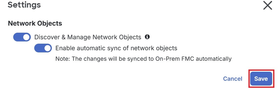
If Cloud-Delivered Firewall Management Center is deployed on your tenant: Changes you make to the ASA, FDM, and FTD network objects and groups are reflected in the corresponding Cloud-Delivered Firewall Management Center network object or group. In addition, an entry is created in the Devices with Pending Changes page for each on-premises Firewall Management Center with Discover & Manage Network Objects enabled, from which you can choose and deploy the changes to the on-premises Firewall Management Center on which you have these objects. Deleting a network object or group from either page deletes the object or group from both pages. |
Procedure
|
Step 1 |
In the left pane, click Objects. |
|
Step 2 |
Locate the object you want to delete by using object filters and the search field, and select it. |
|
Step 3 |
Review the Relationships pane. If the object is used in a policy or in an object group, you cannot delete the object until you remove it from that policy or group. |
|
Step 4 |
In the Actions pane, click the Remove icon |
|
Step 5 |
Confirm that you want to delete the object by clicking OK. |
|
Step 6 |
Review and deploy the changes you made, or wait and deploy multiple changes at once. |
 .
.
Delete a group of unused objects
As you onboard devices and start resolving object issues, you find many unused objects. You can delete up to 50 unused objects at a time.
Procedure
|
Step 1 |
Use the Issues filter to find unused objects. You can also use the Device filter to find objects that are not associated with a device by selecting No Device. |
|
Step 2 |
Check the Select all checkbox in the object table header to select all the objects found by the filter that appear in the object table; or, check individual checkboxes for individual objects you want to delete. |
|
Step 3 |
In the Actions pane, click the Remove icon |
|
Step 4 |
Review and deploy now the changes you made, or wait and deploy multiple changes at once. |
 to create an object.
 in the
  arrow in
  arrow in
  to create an object.
 appearing beside the object name or network group to modify them.


 Feedback