The documentation set for this product strives to use bias-free language. For the purposes of this documentation set, bias-free is defined as language that does not imply discrimination based on age, disability, gender, racial identity, ethnic identity, sexual orientation, socioeconomic status, and intersectionality. Exceptions may be present in the documentation due to language that is hardcoded in the user interfaces of the product software, language used based on RFP documentation, or language that is used by a referenced third-party product. Learn more about how Cisco is using Inclusive Language.
This table describes the developments of this feature, by release.
Table 1. Feature history
Feature name
Release information
Description
Symmetric Routing
Cisco IOS XE Catalyst SD-WAN Release 17.12.1a
Cisco Catalyst SD-WAN Control Components Release 20.12.1
You can use affinity groups, affinity group preferences, and RIB metric translation to ensure devices route traffic flows
symmetrically across the network.
Symmetric routing supports a wide range of network topologies, including Multi-Region Fabric. Transport gateways translate
RIB metrics into control plane protocols such as BGP and OSPF to extend symmetric routing beyond the overlay network. This
translation applies the path-preference configuration to routers outside the overlay network, including routers in a data
center LAN.
Symmetric routing mechanisms for Cisco SD-WAN
A symmetric routing is a traffic flow property that
uses the same path for traffic in both directions
maintains a consistent return path between endpoints, and
supports features that require bidirectional path symmetry.
Some networking functionality requires symmetric routing to operate correctly, including Cisco NBAR2, Cisco Zone-Based Firewall
(ZBF), Cisco Unified Threat Defense (UTD), Cisco Application Quality of Experience (AppQoE), and network address translation
(NAT).
Within a Cisco Catalyst SD-WAN network, you can use affinity groups, affinity group preference, control policy, and other mechanisms to configure the network
so that the preferred route between two endpoints remains consistent for traffic in both directions. This configuration ensures
symmetric routing for traffic flows between those endpoints. In some scenarios, you can also ensure symmetric routing for
traffic flows that extend to a device outside the Cisco Catalyst SD-WAN overlay network.
TLOC behavior when moving away from symmetric NAT
When a TLOC starts behind symmetric NAT and then moves to any other NAT type such as full cone, port-restricted cone, or restricted
cone, the TLOC does not update its public IP or port. The learned NAT type of the TLOC also does not update. As a result,
some or all BFD sessions for this TLOC go down. To recover from this state, you can run clear sdwan control connections from the edge router.
Assumption about router operation
All of this applies only when routers stay operational during a traffic flow. If a router in the path becomes inoperable,
traffic must take a new route. This change can cause temporary asymmetric routing.
Benefits of symmetric routing configuration
Before Cisco IOS XE Catalyst SD-WAN Release 17.12.1a configuring symmetric routing required complex and error-prone control policies in the overlay network. These policies set
up hop-by-hop routing in both directions.
In service-side routing, it required complex route-maps to maintain path symmetry in both directions.
From Cisco IOS XE Catalyst SD-WAN Release 17.12.1a onward, you can use affinity groups, affinity group preferences, and OMP metric redistribution to achieve symmetric routing.
The following sections describe the details and supported scenarios.
Restrictions for symmetric routing
You cannot use both the redistribute omp translate-rib-metric command and the redistribute omp metric command together on the same device.
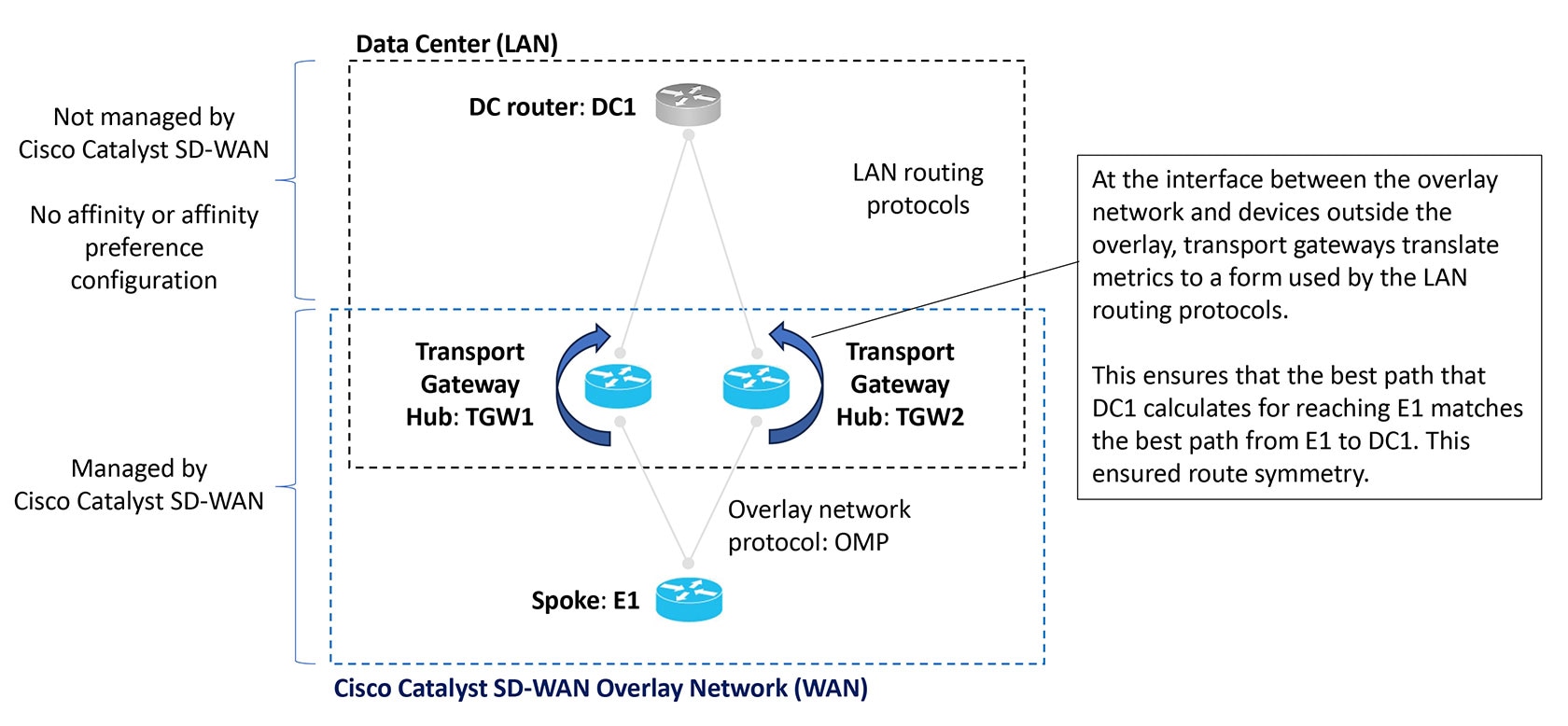
Translating OMP metrics for devices outside of the overlay network
A router configured as a transport gateway and operating as a hub (TGW1 in the illustration below) may conduct traffic between
devices within the Cisco Catalyst SD-WAN overlay network (WAN) and a device outside of the overlay network (LAN), such as DC1 in the following illustration. This
is WAN-to-LAN traffic. Note that devices outside of the overlay network are not managed by Cisco Catalyst SD-WAN.
A transport gateway translates RIB metric information into parameters used by the BGP or OSPF protocols. It uses those parameters
in its BGP or OSPF routing tables, and when the transport gateway advertises routes to its BGP or OSPF neighbors, it includes
the RIB-derived parameters with the routes.
These RIB-derived parameters influence path selection by devices in the LAN, helping to ensure that the LAN chooses the same
path for LAN-to-WAN traffic as the overlay network uses for WAN-to-LAN traffic.
Figure 1. Translating OMP metrics
Translating OMP metrics to BGP attributes
When you enable a router to translate RIB metrics from OMP to BGP, the router uses the following OMP metric and attribute:
OMP route metric
Among the OMP metrics, one specific metric is named OMP.
OMP AS-PATH
The router uses these to derive three BGP attributes:
BGP MED
BGP LOCAL_PREF
BGP AS_PATH
For information about how to view OMP metrics for a route and the resulting BGP attributes, see Monitor RIB metric translation.
Translation from OMP to BGP
Table 2. Translation of OMP metrics to BGP attributes
BGP Attribute
How it is derived
BGP MED
Equal to the OMP route metric.
BGP LOCAL_PREF
255 – (OMP route metric)
BGP AS_PATH
Two possibilities:
If the propagate-aspath command is used:
If OMP AS-PATH is empty, then the router uses its own local AS value and repeats it (OMP route metric) times, with a maximum
of 13 repetitions.
If OMP AS-PATH is not empty, then the router uses the OMP AS-PATH and prepends it with the first AS in the OMP AS-PATH (OMP
route metric) times, with a maximum of 13 times.
If the propagate-aspath command is not used:
The router uses a list of its own local AS value, repeated (OMP route metric) times, prepending the value up to a maximum
of 13 repetitions.
AS-PATH propagation recommendation
In most scenarios, when you enable translation of RIB metrics using the redistribute omp translate-rib-metriccommand, also enable propagating the AS-PATH metric using the propagate-aspath command. If you omit this, the router treats the AS-PATH metric as empty.
The router includes these BGP attributes with the routes that it re-originates to a device in a LAN outside the overlay network
that uses BGP.
BGP attributes without RIB metric translation
The table below shows combinations of OMP metrics and the BGP attributes that the router derives when RIB metric translation
is not enabled.
Table 3. Translation from OMP to BGP without RIB metric translation enabled
OMP metrics:
Example combinations
Translation to BGP attributes:
propagate-aspath enabled
translate-rib-metric not enabled
Example
OMP route metric
OMP AS-PATH
BGP MED
BGP LOCAL_PREF
BGP AS_PATH
1
0
100 101
1000
50
100 101
2
1
100 101
1
50
100 101
3
2
100 101
2
50
100 101
4
10
(empty)
10
50
(empty)
5
14
100 101
14
50
100 101
BGP attributes without RIB metric translation
The table below shows combinations of OMP metrics and the BGP attributes that the router derives when RIB metric translation
is not enabled.
Table 4. Translation from OMP to BGP without RIB metric translation enabled
OMP metrics:
Example combinations
Translation to BGP attributes:
propagate-aspath enabled
translate-rib-metric not enabled
Example
OMP route metric
OMP AS-PATH
BGP MED
BGP LOCAL_PREF
BGP AS_PATH
1
0
100 101
1000
50
100 101
2
1
100 101
1
50
100 101
3
2
100 101
2
50
100 101
4
10
(empty)
10
50
(empty)
5
14
100 101
14
50
100 101
Translating OMP metrics to an OSPF metric
If you do not configure the router to translate RIB metrics, it uses a default OSPF metric when it redistributes routes to
a device outside the Cisco Catalyst SD-WAN overlay network. The default OSPF metric is 16777214 (hexadecimal FFFFFE).
When you enable the router to translate RIB metrics, it assigns the OMP route metric value as the OSPF metric. For example,
if the OMP route metric is 10, the OSPF metric is also 10.
For information about viewing the OMP metrics for a route and the resulting BGP metrics, see Monitor RIB Metric Translation.
Symmetric routing scenarios
An overview of the configuration workflow helps you understand the scenarios in which Cisco Catalyst SD-WAN supports symmetric routing. The figures below shows
a transport gateway scenario, and
a Multi-Region Fabric scenario.
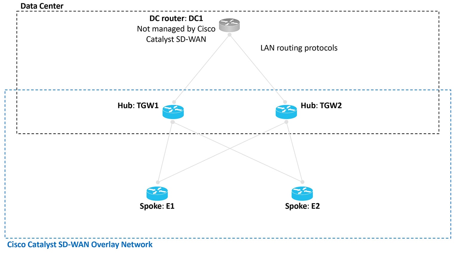
Transport gateway scenario
In the transport gateway scenario, the goal is to ensure symmetric routing between the spoke devices (E1 and E2 in the illustration)
and the data center router (DC1).
Figure 2. Transport gateway scenario with a data center LAN
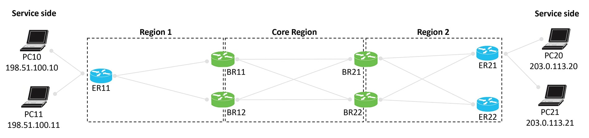
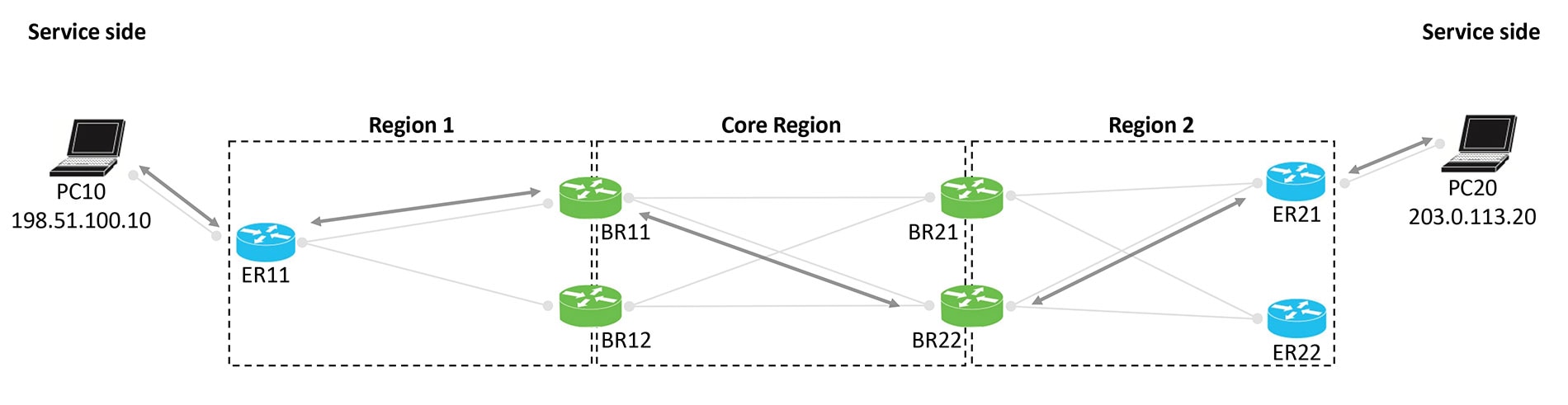
Multi-region fabric scenario
In the Multi-region fabric scenario, the goal is to ensure symmetric routing between the PC devices served by edge router
ER11 in Region 1, and the PC devices served by ER21 in Region 2.
Figure 3. Multi-region fabric scenario
Configuration overview
The steps below provide an overview of the configuration required for symmetric routing.
Configuration step
Devices
Description
1. Configure affinity group preference
Spoke routers
Edge routers in a multi-region fabric scenario
To ensure traffic symmetry within the overlay network, configure spoke routers (or edge routers in a multi-region fabric scenario)
in the network with an affinity group preference. This can be a manually configured order of preference or automatic preference.
With automatic affinity preference order, a spoke device or edge router prefers paths tagged with a lower affinity group number.
To ensure traffic symmetry within the overlay network, configure border routers and transport gateways with (a) an affinity
group number, or (b) affinity groups per VRF for some or all VRFs that the devices handle. You can configure both (a) and
(b) together.
For example, if a device has a VRF range of 1 to 10, you can configure a device as follows:
System-level affinity group 10
Affinity groups per VRF: Affinity group 20 for VRF6 through VRF 10
The result is that vRoutes in the range 1 to 5 are tagged with affinity group 10 (from the system-level affinity group), and
vRoutes in the range of 6 to 10 are tagged with affinity group 20.
To enable symmetric routing between the overlay network and a LAN, on the border routers or transport gateways that conduct
traffic with a LAN, enable translation of RIB metrics for redistribution of OMP routes to LAN routing protocols.
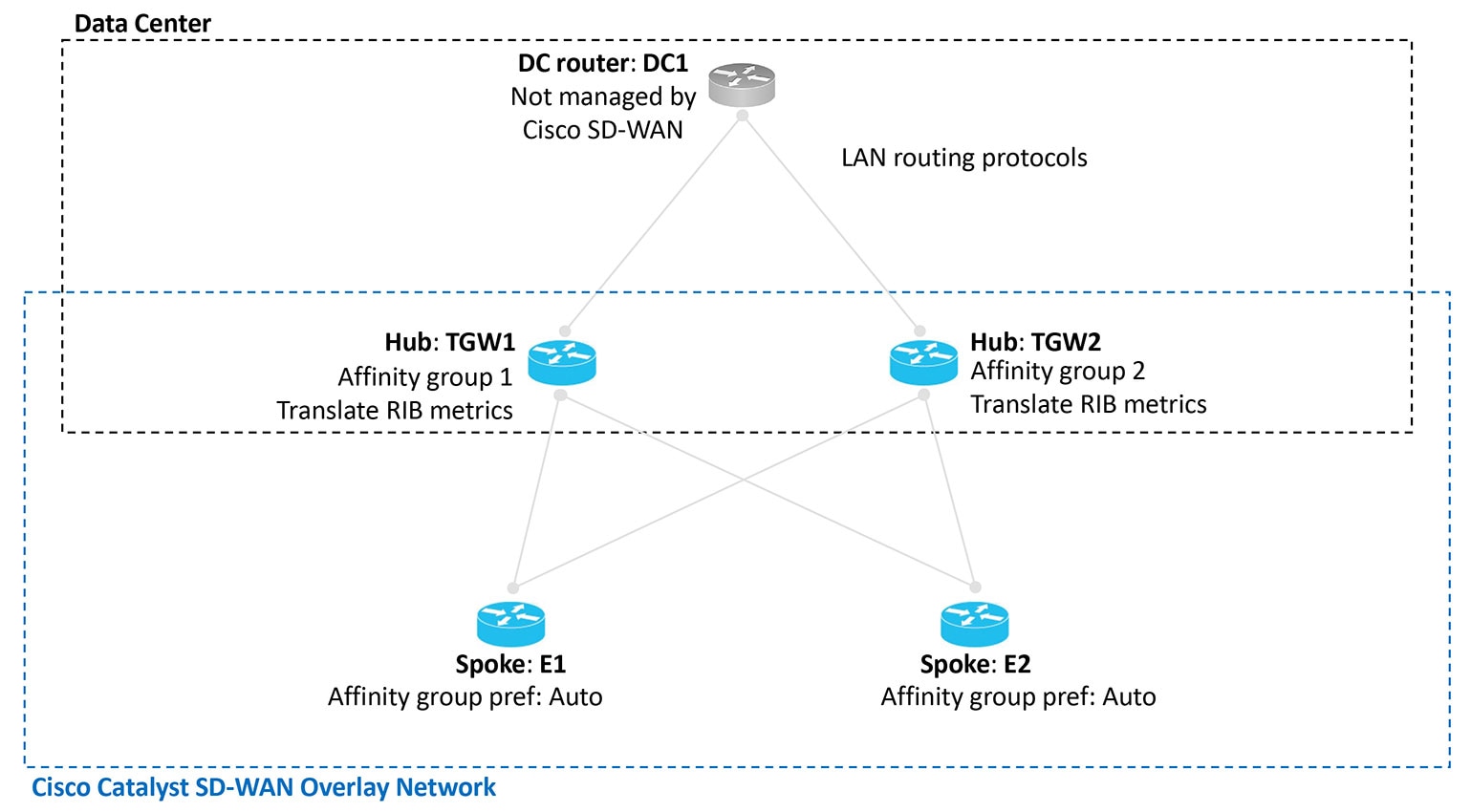
Example configurations for symmetric routing in transport gateway and multi-region fabric deployments
The illustrations below show the two scenarios described earlier, with an example configuration for each router, in accordance
with the steps described here to ensure symmetric routing.
Figure 4. Transport gateway scenario with a data center LAN, showing a configuration for symmetric routing
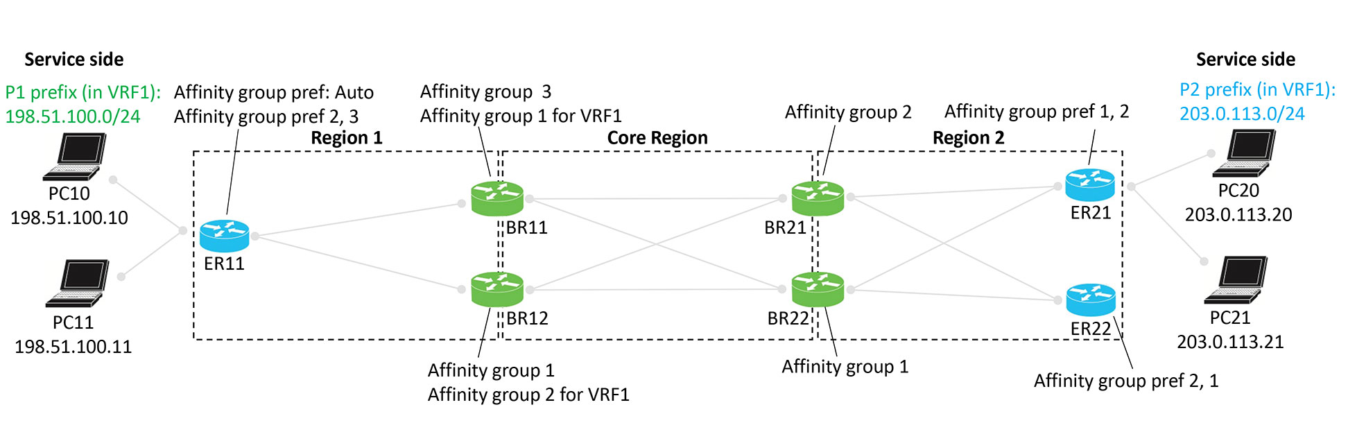
Figure 5. Multi-region fabric scenario, showing a configuration for symmetric routing
Example of configuration for symmetric routing and the mechanism
This comprehensive example describes how to configure border routers and edge routers in a Multi-Region Fabric (MRF) environment
to achieve symmetric routing between PC devices behind ER11 (Region 1) and ER21 (Region 2).
The example focuses specifically on traffic between PC10 and PC20.
The step-by-step illustrations show how route re-origination and path preference ensure that traffic in both directions follows
the same path across multiple hops.
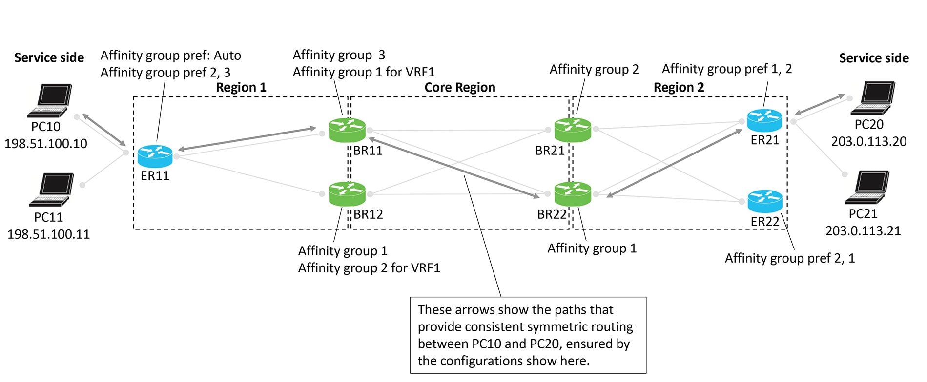
Multi-region fabric scenario: configuration for symmetric routing
Figure 6. Multi-region fabric scenario, configuration for symmetric routing
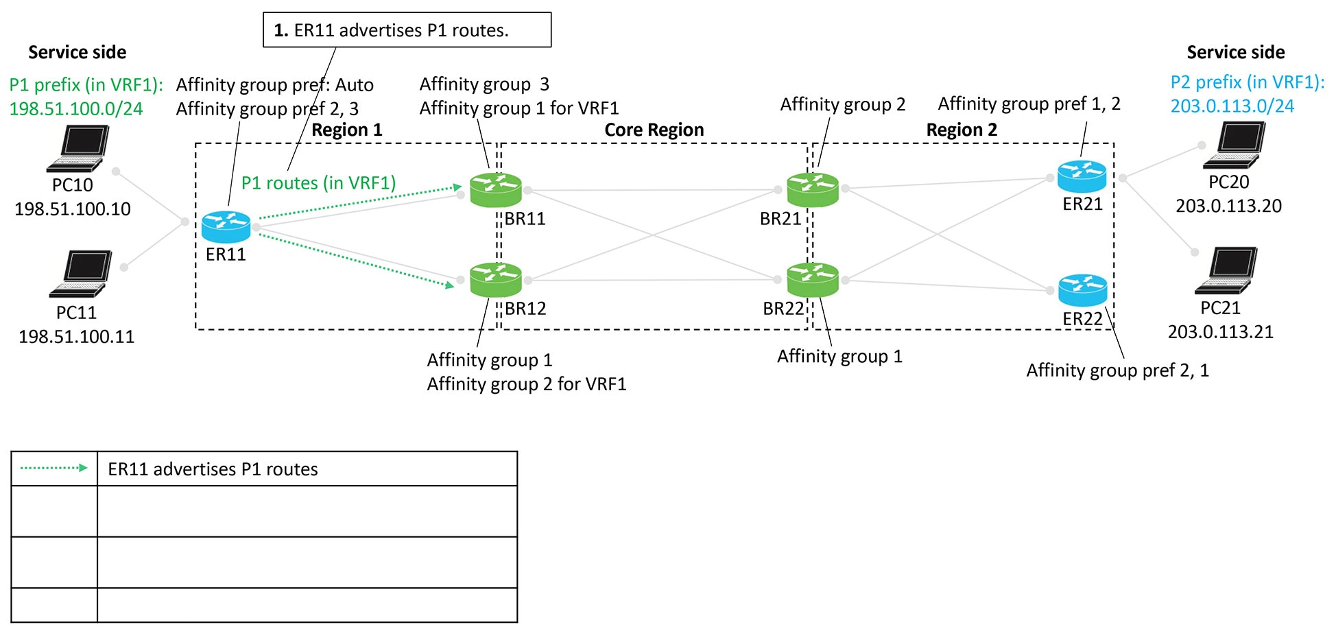
Advertising P1 routes
Edge router ER11 advertises P1 routes. These routes are re-originated as they move from Region 1 toward Region 2, passing
through border routers that assign affinity groups and derived affinity groups (DAG).
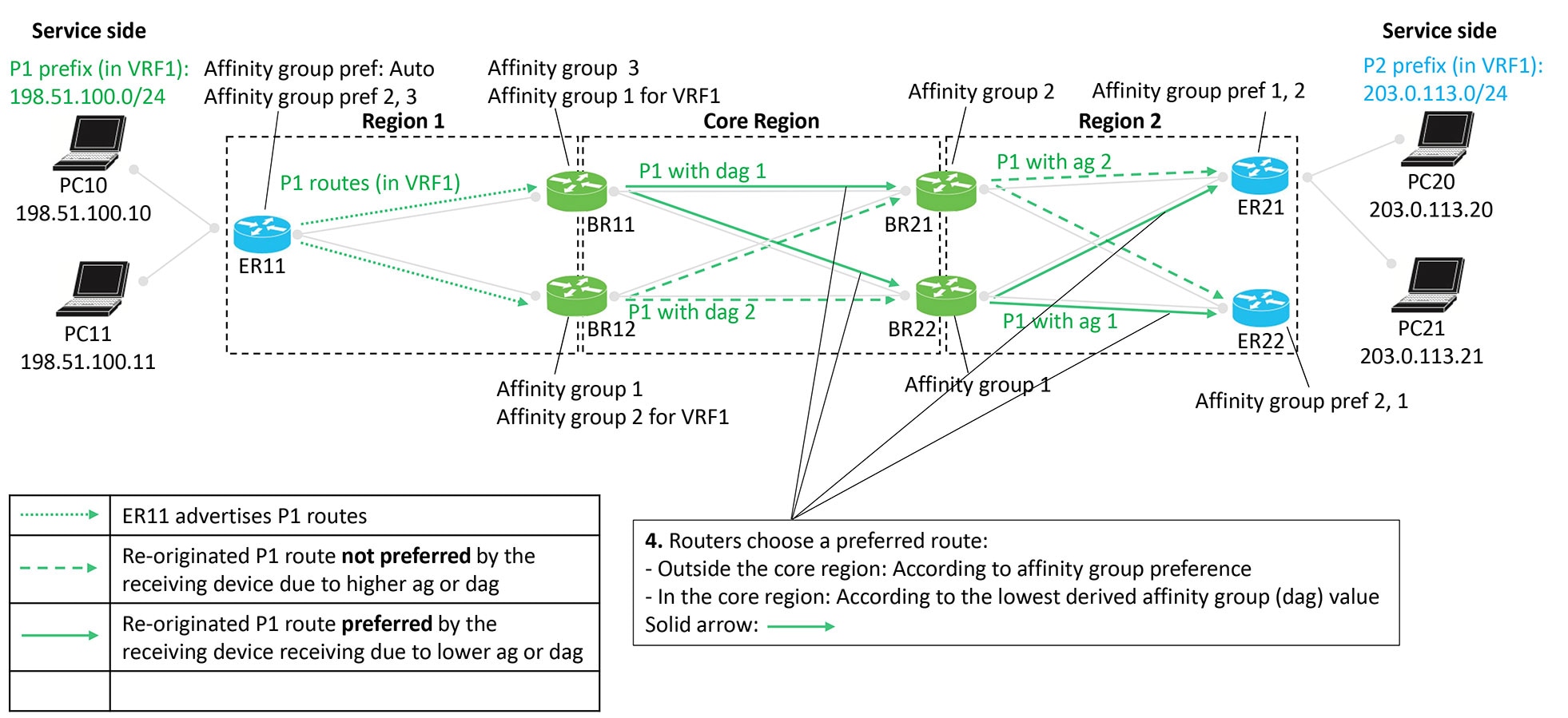
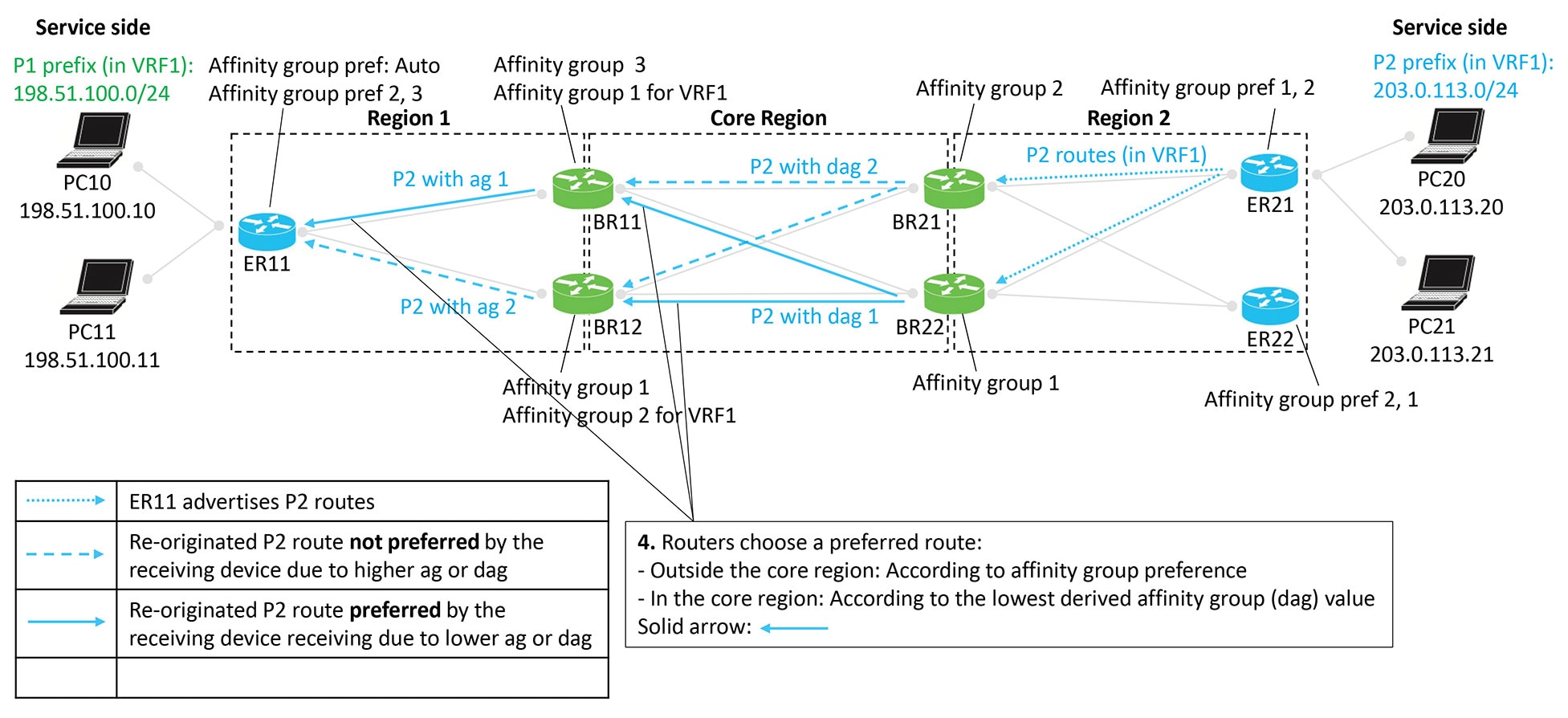
Routers select preferred routes based on:
Outside the core region: Affinity group preference
Inside the core region: Lowest derived affinity group (dag) value
Figures:
Figure 7. Edge router ER11 advertises P1 routes
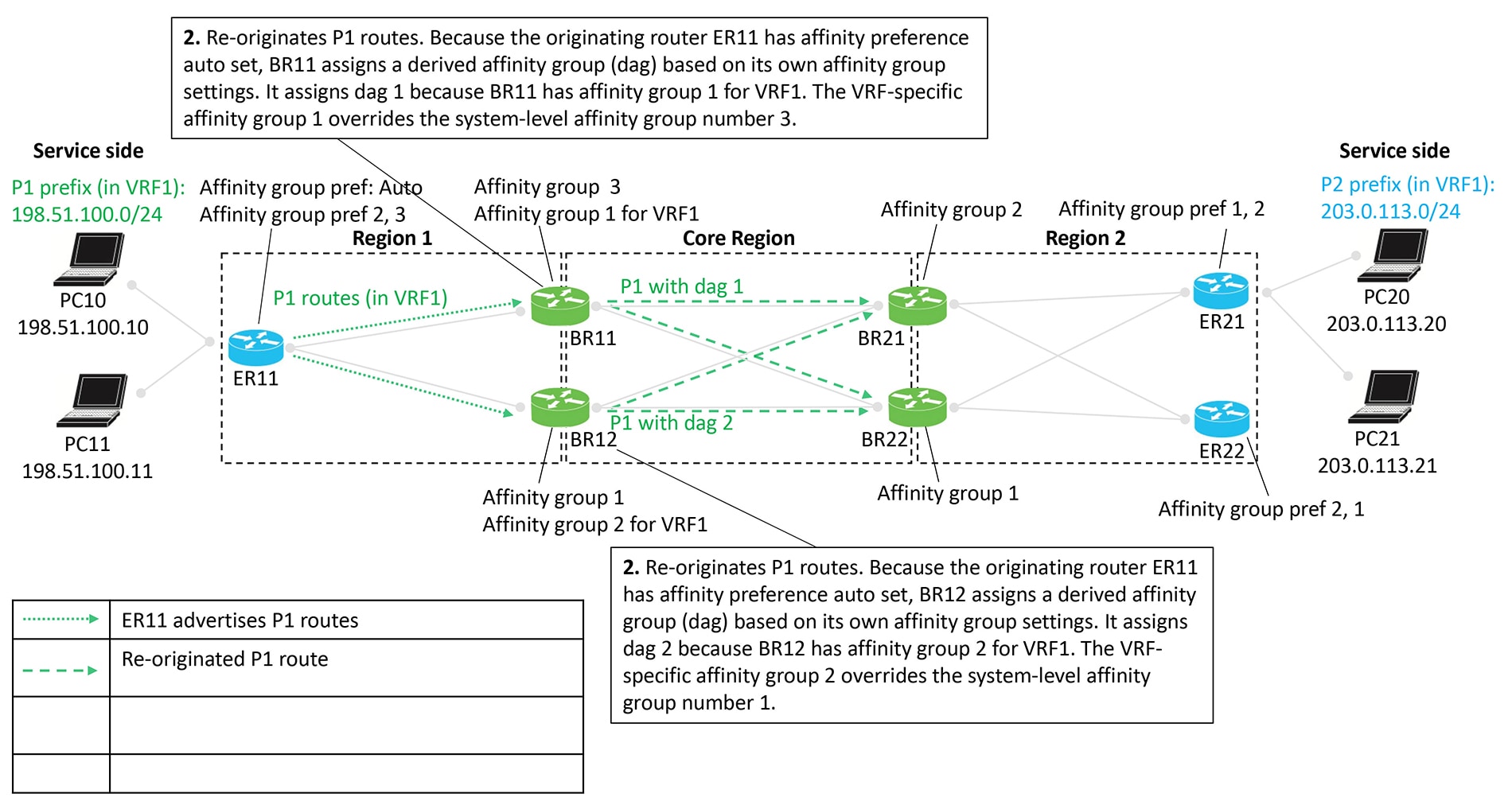
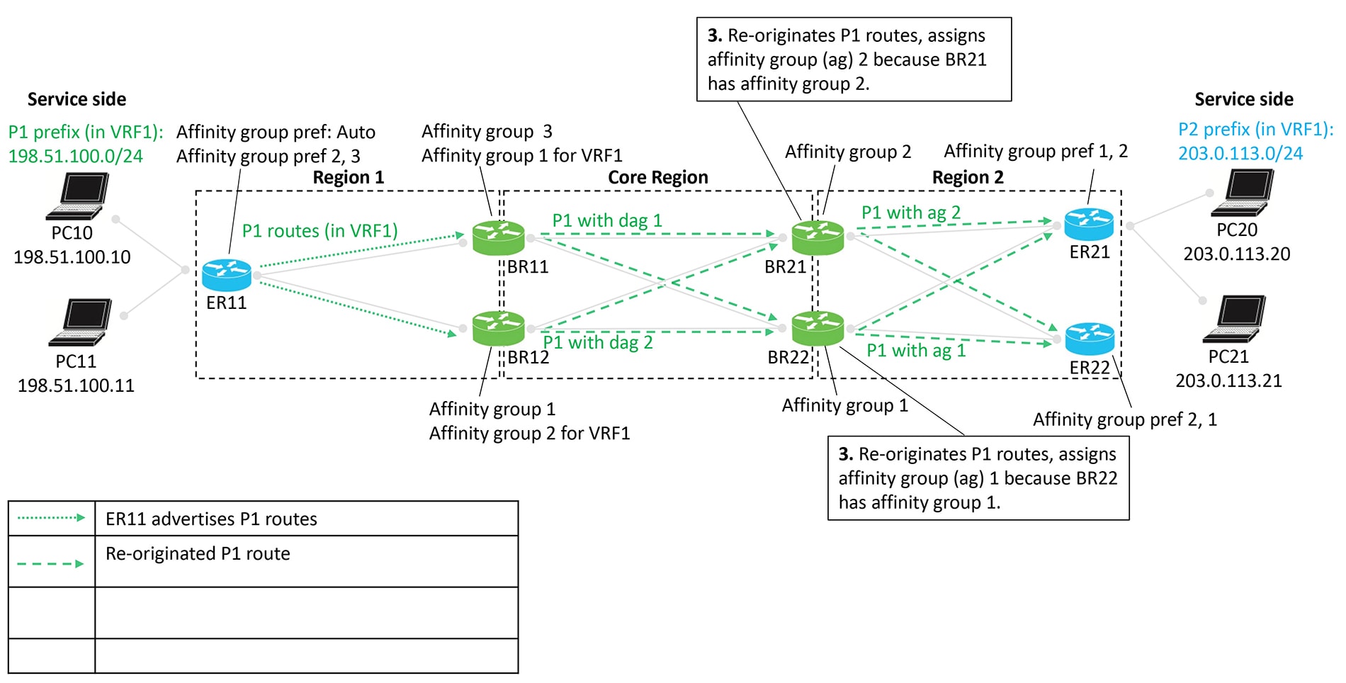
Figure 8. Border routers BR11 and BR12 re-originate the P1 routes
Figure 9. Border routers BR21 and BR22 re-originate the P1 routes
Figure 10. Route preference according to affinity group and derived affinity group
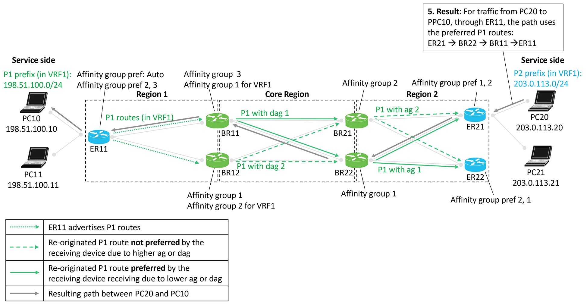
Figure 11. Resulting path of traffic to P1
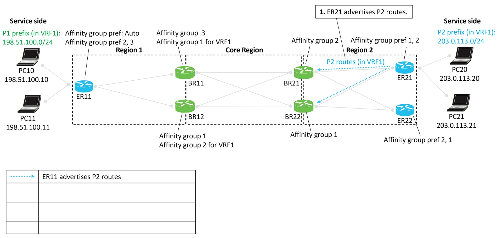
Advertising P2 routes
Edge routers ER21 and ER22 advertise P2 routes. These routes are re-originated from Region 2 back toward Region 1, with border
routers again assigning affinity groups and derived affinity groups during the process.
Route preference is determined using the same rules:
Outside the core region: Affinity group preference
Inside the core region: Lowest derived affinity group (dag) value
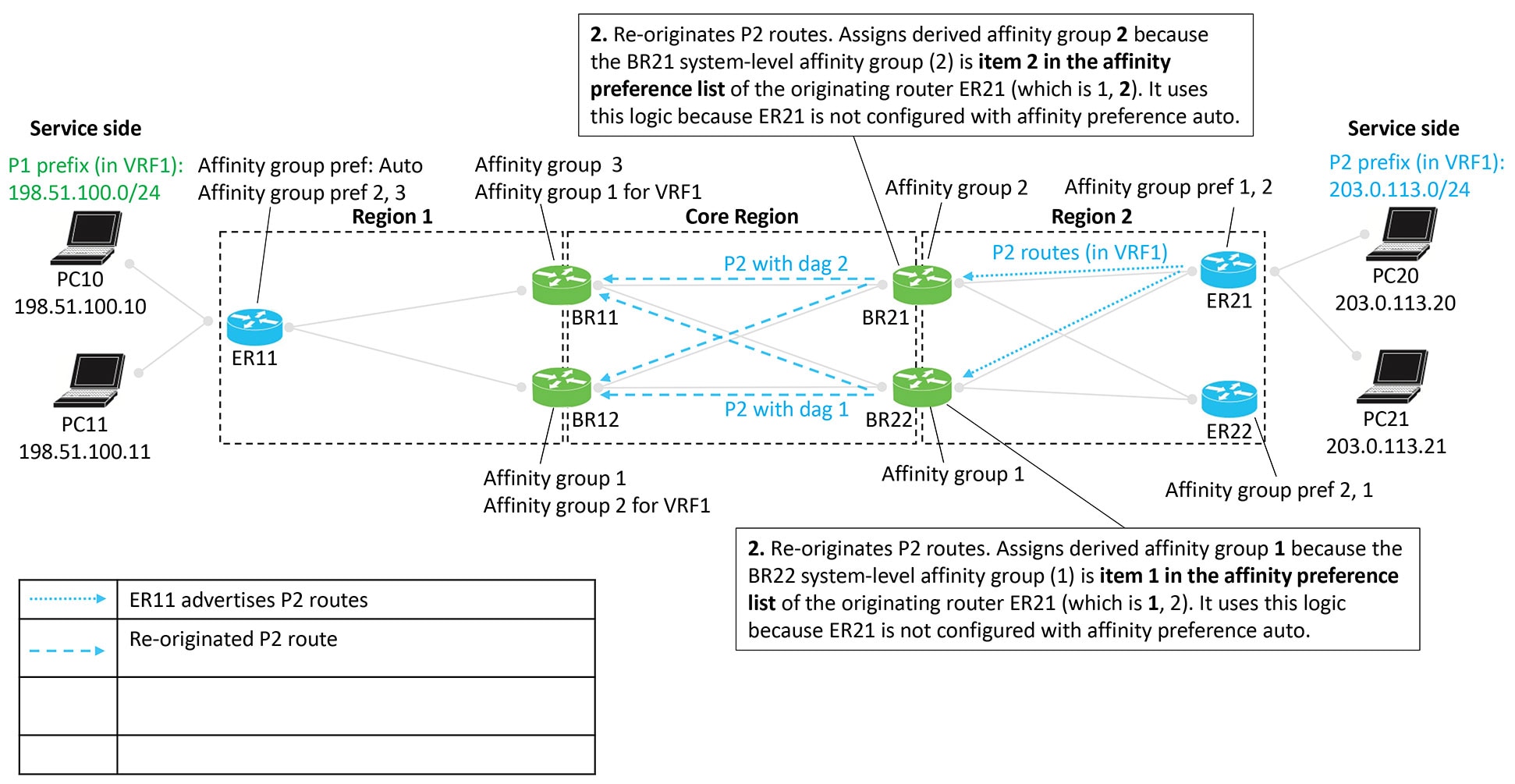
Figure 12. Edge router ER21 advertises P2 routes
Figure 13. Border routers BR21 and BR22 re-originate the P2 routes
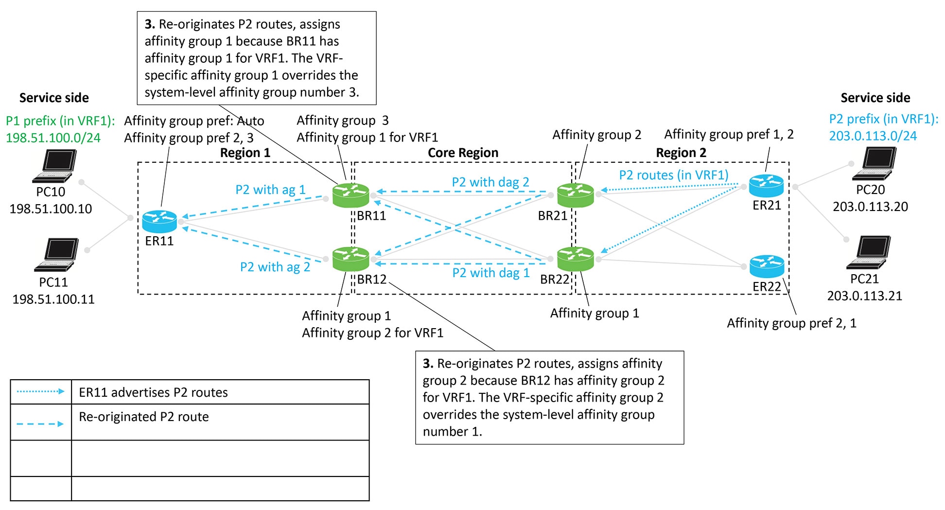
Figure 14. Border routers BR11 and BR12 re-originate the P2 routes
Figure 15. Route preference according to affinity group and derived affinity group
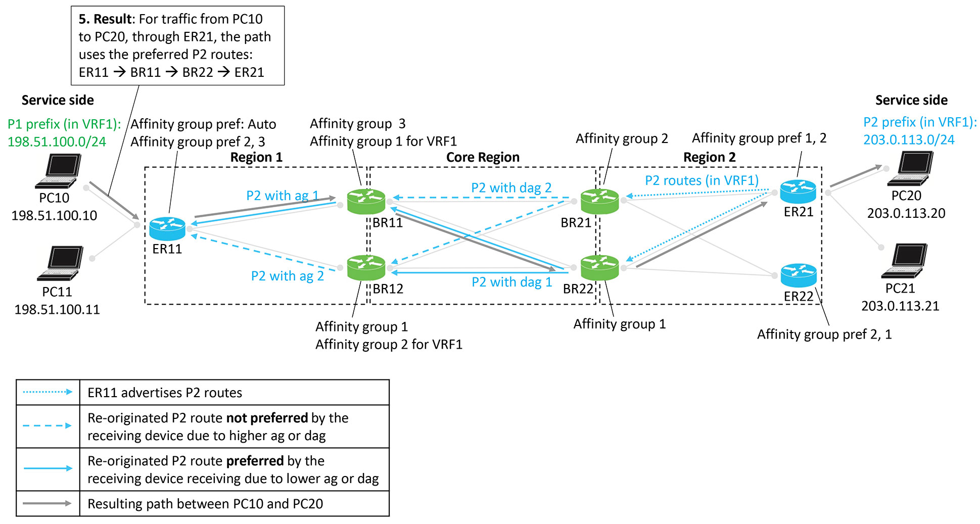
Figure 16. Resulting path of traffic to P2
Result
The following figure shows that the result of the configuration is symmetric routing for flows between, in this example, PC10
and PC20:
Figure 17. Result is symmetric routing
Supported scenarios
The symmetric routing configuration method described in this document applies to the following deployment scenarios:
Hub-and-spoke topology with multiple hub routers: includes deployments where the hub router provides connectivity to a multi-homed
data center.
Multi-region fabric with multiple border routers: Covers scenarios where an MRF region contains a multi-homed data center,
requiring consistent bidirectional path selection across regions.
Multi-region fabric with transport gateways serving subregions: Applies to MRF deployments where transport gateways (TGWs)
connect subregions and influence route propagation.
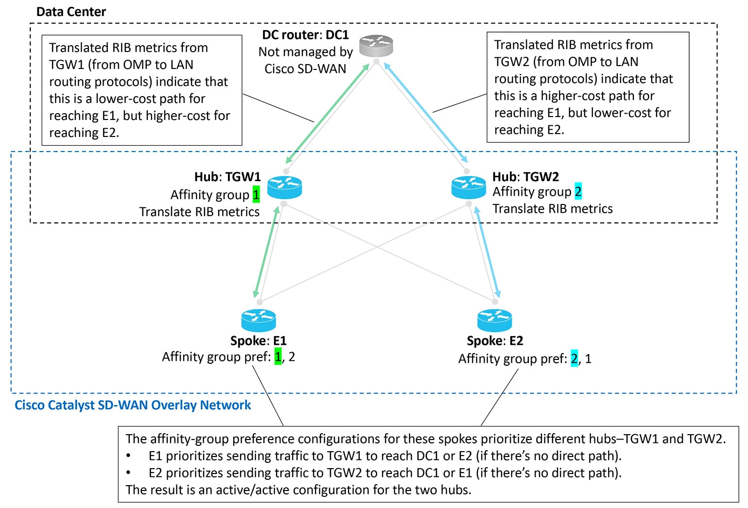
Scenario: Hub-and-spoke topology, multiple hubs serving a data center, active/active
In this scenario, two hubs serve a data center. The two hubs are both active, for an active/active arrangement.
The data center LAN is not part of the Cisco Catalyst SD-WAN overlay network.
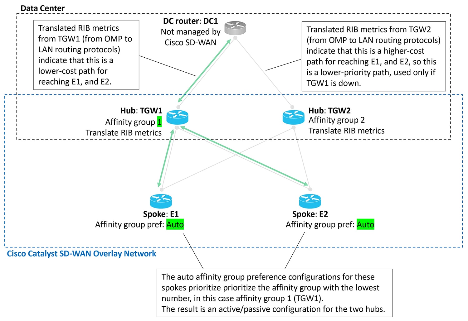
Scenario: Hub-and-spoke topology, multiple hubs serving a data center, active/passive
In this scenario, two hubs serve a data center. Only one hub is typically active, and the other is stand-by, in case the active
hub becomes unavailable. This is an active/passive arrangement.
The data center LAN is not part of the Cisco Catalyst SD-WAN overlay network.
Figure 19. Data center, two hubs, active/passive
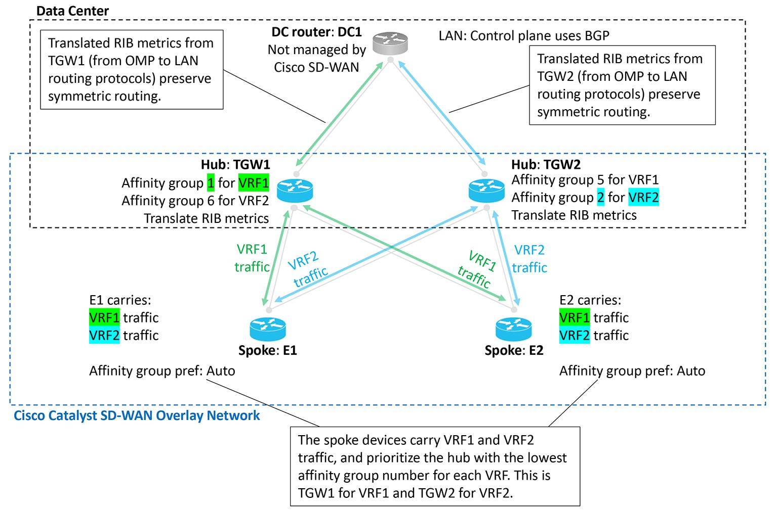
Scenario: Hub-and-spoke topology, multiple hubs serving a data center, active/active by VRF
In this scenario, two hubs serve a data center. The two hubs are both active, for traffic in one of the two VRFs. This is
an active/active arrangement, segregated by VRF. The hub TGW1 is active for VRF1 and the hub TGW2 is active for VRF2. Both
hubs can operate as stand-by for the other VRF.
The data center LAN is not part of the Cisco Catalyst SD-WAN overlay network.
Figure 20. Data center, two hubs, active/active, segregated by VRF
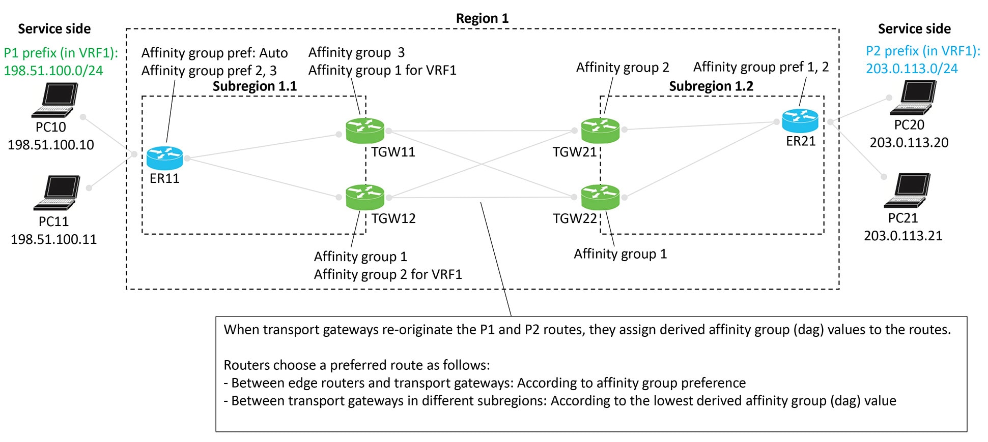
Scenario: Multi-region fabric, transport gateways serving subregions
Similarly to the border routers in the comprehensive example, transport gateways assign a derived affinity group (dag) to
routes that they re-originate to other transport gateways. As described in the illustration:
When transport gateways re-originate routes, they assign derived affinity group (dag) values to the routes.
Routers choose a preferred route as follows:
Between edge routers and transport gateways: According to affinity group preference
Between transport gateways in different subregions: According to the lowest derived affinity group value
Figure 21. Multi-region fabric with transport gateways serving subregions
Similarly to the border routers in the comprehensive example, transport gateways assign a derived affinity group (dag) to
routes that they re-originate to other transport gateways. This scenario is similar to the one described in Scenario: Multi-Region Fabric, Transport Gateways Serving Subregions, but with route leaking. As described in the illustration:
When transport gateways re-originate routes, they assign derived affinity group (DAG) values to those routes.
Routers select a preferred route in the following ways:
Between edge routers and transport gateways: They use affinity group preference.
Between transport gateways in different subregions: They choose the route with the lowest derived affinity group value.
In this scenario, a control policy on the Cisco SD-WAN Controllers leaks routes from VRF1 to VRF2 and from VRF2 to VRF1. This
route leaking enables endpoints in different VRFs to communicate.
This route-leaking scenario clearly shows how transport gateways (or border routers) assign a derived affinity group (DAG)
when they re-originate routes. The logic works subtly, but this example highlights it well.
Default behavior
In this example, the edge routers and transport gateway routers operate as follows:
ER11 subscribes only to VRF1 and advertises prefix P1 in VRF1.
ER21 subscribes only to VRF2 and advertises prefix P2 in VRF2.
All transport gateway routers handle traffic for both VRF1 and VRF2, so they re-originate both P1 (in VRF1) and P2 (in VRF2).
By default, the network enforces VRF isolation. When a device advertises routes in different VRFs, the Cisco SD-WAN Controllers
filter those routes before sending them to other devices. A controller advertises a VRF x route only to devices that subscribe
to VRF x.
Therefore, in this example:
ER11, which subscribes only to VRF1, does not receive P2 routes from VRF2.
ER21, which subscribes only to VRF2, does not receive P1 routes from VRF1.
As a result, VRF isolation blocks traffic between ER11 and ER21 because each router subscribes exclusively to a different
VRF.
Route leaking
Route leaking allows devices to advertise routes across VRFs by exporting (“leaking”) a route from one VRF into another.
Source VRF: the route’s original VRF
Current VRF: the VRF into which the route was exported
When routers advertise exported routes, they track both the source VRF and the current VRF, preserving the background of each
route. This tracking becomes important in the logic described later.
In this example, the following route-leaking policies apply:
An inbound control policy for ER11 instructs it to receive VRF1 routes and export them into VRF2.
Result: ER11 advertises prefix P1 in both VRF1 and VRF2 to its transport gateways, TGW11 and TGW12.
An inbound control policy for ER21 instructs it to receive VRF2 routes and export them into VRF1.
Result: ER21 advertises prefix P2 in both VRF2 and VRF1 to its transport gateways, TGW21 and TGW22.
As mentioned earlier, after leaking routes, devices continue to track each route’s source VRF and current VRF.
Calculating the derived affinity group (DAG)
A transport gateway device or a border router in a similar scenario assigns a derived affinity group (DAG) to any route it
re-originates using the following logic:
If the originating router is configured with affinity group preference auto (see ER11 in the example), then the re-originating device (for example, TGW11)
determines the dag according to its own (TGW11's) affinity group configuration, as follows:
For the leaked route, consider its source VRF and current VRF. Choose the numerically lower of the two values. Call this x.
Do one of the following:
If the re-originating device only has a system-level affinity group, not VRF-specific affinity groups, then:
Use the system-level affinity group number for the dag. Assign a dag of that number when re-originating the route.
If the re-originating device has a VRF-specific affinity group configured for VRF x described in step a, then:
Use this VRF-specific affinity group number for the dag. Assign a dag of this number when re-originating the route.
If the originating router is not configured with affinity group preference auto (see ER21 in the example), then the re-originating device (for example, TGW21)
must consider the affinity preference order configured on the originating device when determining the dag for re-originated
routes, as follows:
For the leaked route, consider its source VRF and current VRF. Choose the numerically lower of the two values. Call this x.
Do one of the following
If the re-originating device only has a system-level affinity group, not VRF-specific affinity groups, then:
Check the affinity group preference order of the originating device (see ER21). Determine the item number of where the system-level
affinity group number occurs in the preference order (item 1, 2, 3, and so on, in the preference order list). Assign a dag
of this item number when re-originating the route.
In the example of TGW21 and ER21, determine where affinity group 2 occurs in the preference order of ER21, which is (1, 2).
It is item 2 in the list. So assign a dag of 2 when re-originating the route.
If the re-originating device has a VRF-specific affinity group configured for VRF x described in step a, then:
Using this VRF-specific affinity group, check the affinity group preference order of the originating device. Determine the
item number of where the VRF-specific affinity group number occurs in the preference order (item 1, 2, 3, and so on, in the
preference order list). Assign a dag of this item number when re-originating the route.
Hypothetically, in the example, if TGW21, in addition to having a system-level affinity group of 2, also had a VRF-specific
affinity group of 1 for VRF1, then when TGW21 received from ER21 a P2 route leaked to VRF1, it would consider the preference
order of the originating device (ER21). In this hypothetical example with a VRF-specific affinity group of 1, for a route
received from ER21, it would check where affinity group 1 occurs in the preference order of ER21, which is (1, 2). It is item
1 in the list. So TGW2 would assign a dag of 1 when re-originating the route.
Example
In the scenario shown in the illustration, a route leaked from VRF2 to VRF1 has a source VRF value of 2 and a current VRF
value of 1. When a transport gateway re-originates this route, it assigns a DAG based on the number 1, which is the lower
of the two VRF numbers. For example, if TGW12 re-originates a route with a source VRF value of 1 and a current VRF value of
2, it chooses 1 because it is the lower of the two VRF numbers. It therefore calculates the DAG according to VRF1. TGW12 has
a system-level affinity group of 1 and a VRF-specific affinity group of 2 for VRF1. Since it calculates the DAG according
to VRF1, it assigns the re-originated route a DAG value of 2, taken from the VRF-specific affinity group.
In a hypothetical scenario, if TGW12 had a system-level affinity group of 5 and a VRF1-specific affinity group of 7, then
for a route with source VRF 1 and current VRF 2, TGW12 would assign a DAG of 7, taken from the VRF-specific affinity group
of 7 for VRF1.
Figure 22. Multi-region fabric with subregions, route leaking
Configure symmetric routing
Use these procedures to configure symmetric routing.
Configure a router to use automatic affinity group preference using templates
If you configure both a manual affinity preference order and an auto preference order on a router, the router gives priority
to the auto preference order when selecting the next hop.
From the Cisco SD-WAN Manager menu, choose ConfigurationTemplates.
Step 2
Click Feature Templates.
Step 3
Do one of the following:
To create a System template for a device, click Add Template, choose a device type, and click Cisco System.
To edit an existing System template, locate a System template in the table of existing feature templates, click … adjacent to the template, and choose Edit.
Step 4
In the Affinity Group Preference Auto field, choose On.
Step 5
Click Save if creating a new template, or Update if editing an existing template.
Configure a router to use automatic affinity group preference, using CLI commands
If you configure a router with both affinity-group preference-auto and affinity-group preference list, the affinity-group preference-auto command has priority for selecting a next hop.
However, the affinity-group preference list command is still useful for path filtering using the filter route outbound affinity-group preference command.
For more information about using CLI templates, see CLI Add-On Feature Templates and CLI Templates. By default, CLI templates execute commands in global configuration mode.
Procedure
Step 1
Enter system configuration mode.
system
Step 2
Configure automatic affinity group preference.
affinity-group preference-auto
Configure router affinity groups for specific VRFs
Use any one of these methods configure router affinity groups for specific VRFs
Configure router affinity groups for specific VRFs using templates
For more information about using CLI templates, see CLI Add-On Feature Templates and CLI Templates. By default, CLI templates execute commands in global configuration mode.
Procedure
Step 1
Enter system configuration mode.
system
Step 2
Configure an affinity group to apply to a specific VRF or range of VRFs.
The following example configures affinity group 1 for VRF1:
system
  affinity-per-vrf 1 vrf-range 1
The following example configures affinity group 4 for the VRF range 3 to 6:
system
  affinity-per-vrf 4 vrf-range 3-6
Configure router affinity groups for specific VRFs using CLI commands
Use these steps to configure router affinity groups for specific VRFs.
Procedure
Step 1
From the Cisco SD-WAN Manager menu, choose Configuration > Templates.
Step 2
Click Feature Templates.
Step 3
Do one of the following:
To create a System template for a device, click Add Template, choose a device type, and click Cisco System.
To edit an existing System template, locate a System template in the table of existing feature templates, click … adjacent to the template, and choose Edit.
Step 4
For Affinity Group Number for VRFs, there are two fields. In the left field, enter an affinity group number. In the right
field, enter a VRF number or a range of numbers–for example, 2-4. To configure addition group numbers for specific VRFs, click
the plus button.
Verify the next hops for a specific prefix on a router
Use show sdwan omp routes prefix on a router to show the next hops for a specific prefix.
Device# show sdwan omp routes 10.1.1.0/24
Verify the path to a destination router
Use traceroute vrf vrf-number destination-ip-address numeric on any device in the network to show the path from the device to a specified destination device, for a specified VRF.
The output shows a list of each hop in the path to the destination device. The last item in the list is the destination device.
Device# traceroute vrf 1 10.1.1.1 numeric
Type escape sequence to abort.
Tracing the route to 10.1.1.1
VRF info: (vrf in name/id, vrf out name/id)
  1 209.165.200.225 3 msec 1 msec 1 msec
  2 209.165.200.226 2 msec 1 msec 1 msec
  3 10.1.1.1 4 msec * 4 msec
Verify the VRF-specific affinity group configuration on a router
Use show platform software sdwan rp active internal "omp daemon" on a transport gateway, or a border router in a Multi-Region Fabric scenario, to show the VRF-specific affinity group configuration
on a router. The output shows the affinity group for each configured VRF range.
See the procedures below for configuring VRF-specific affinity groups:
Device# show platform software sdwan rp active internal "omp daemon" | include Affinity
…
Affinity per VRF:

Affinity Group Number: 1 for VRF Range: 1-1
Affinity Group Number: 5 for VRF Range: 2-8
Verify a control policy for route leaking
Use show running-config policy control-policy on a Cisco SD-WAN Controller to show a control policy that configures route leaking from one VRF to another, if such a policy
exists. Exporting routes from one VRF to another is called leaking routes.
For information about configuring a control policy that matches routes of a VRF list and exports the routes to a specific
VRF, see Configure Centralized Policies Using the CLI.
Verify control policy application
Use show running-config apply-policy on a Cisco SD-WAN Controller to show the sites to which a control policy is applied.
This example shows a control policy that matches VRF1 routes and exports them to VRF2, and matches VRF2 routes and exports
them to VRF1.
sdwanController# show running-config policy control-policy
policy
 control-policy LEAK_1_TO_2
  sequence 1
   match route
    vpn-list VRF1
   !
   action accept
    export-to
     vpn 2
    !
   !
  !
  default-action accept
 !
 control-policy LEAK_2_TO_1
  sequence 1
   match route
    vpn-list VRF2
   !
   action accept
    export-to
     vpn 1
    !
   !
  !
  default-action accept
 !
!
Example 2
The following example shows the sites to which the two policies configured in the previous example are applied.

sdwanController#show running-config apply-policy
apply-policy
 site-list SL1100
  control-policy LEAK_1_TO_2 in
 !
 site-list SL1300
  control-policy LEAK_2_TO_1 in
 !
!
Verify the derived affinity group of a route
Use show sdwan omp routesprefixdetail on a transport gateway, or a border router in a Multi-Region Fabric scenario, to show the derived affinity group assigned
to a prefix. The derived-affinity-group parameter in the output shows the value.
In this example the derived affinity group is 2.
Device# show sdwan omp routes 192.168.1.0/24 detail
…
  preference       not set
  affinity group  None
  derived-affinity-group  2
  affinity-preference-order  None
  region-id          0
  br-preference      not set
To view the OMP RIB metrics for a route, use the show ip route command on a transport gateway that is translating OMP RIB metrics.
The example below shows the OMP RIB metrics for the 10.1.1.1 route. The following metrics are shown in bold in the output:
OMP Route Metric: 3
OMP AS-PATH: 100 101
Device# show ip route vrf 1 10.1.1.1 protocol-internal
Routing Table: 1
Routing entry for 10.1.1.1/32
  Known via "omp", distance 251, metric 3, type omp
  Redistributing via bgp 1
  Advertised by bgp 1
  Last update from 10.100.1.2 00:04:35 ago
  Routing Descriptor Blocks:
  * 10.100.1.2 (default), from 10.100.1.2, 00:04:35 ago
      opaque_ptr 0x7FC8D1470748
        pdb 0x111111111110, ndb 0x111111111120, rdb 0x111111111130
        OMP attribute 0x7FC8D1470748, ref 2
        aspath 0x7FC8D1474870, ref 2, length 10, value 100 101
        Total OMP attr count 1, aspath 1, community 0
      Route metric is 3, traffic share count is 1
OMP route metric for IPv4 routes
To show the OMP route metric for each IPv4 route prefix that a transport gateway is redistributing, use the show ip route command on the transport gateway. The OMP route metric, which is 66, is shown in bold in the output, and the administrative
distance is 251.
device# show ip route vrf 1 omp

Routing Table: 1

      10.0.0.0/32 is subnetted, 1 subnets
m        10.10.10.10 [251/66] via 172.16.0.1, 00:09:15
OMP route metric for IPv6 routes
To show the OMP route metric for each IPv6 route prefix that a transport gateway is redistributing, use the show ipv6 route command on the transport gateway. The OMP route metric, which is 66, is shown in bold in the output, and the administrative
distance is 251.
device# show ipv6 route vrf 1 omp
m   2001:DB8::/128 [251/66]
     via 172.16.0.1%default
…
View BGP metrics
To view the derived BGP metrics for a route, use the show ip bgpcommand on a transport gateway that is translating OMP RIB metrics.
This example shows the derived BGP metrics for the 10.1.1.1 route. Though the example shows an IPv4 route, IPv6 routes are
also supported. The following metrics are shown in bold in the output:
BGP MED: 3
BGP LOCAL_PREF: 252
BGP AS_PATH: 100 100 100 100 101 (This is 100 100 100 (3 copies), plus the original 100 101 of the OMP AS-PATH value.)
device# show ip bgp vpnv4 all 10.1.1.1
BGP routing table entry for 1:1:10.1.1.1/32, version 2
Paths: (1 available, best #1, table 1)
  Advertised to update-groups:
     1
  Refresh Epoch 1
  100 100 100 100 101
    10.100.1.2 (via default) from 0.0.0.0 (10.100.1.1)
      Origin incomplete, metric 3, localpref 252, valid, sourced, best
      Extended Community: SoO:0:0
      mpls labels in/out 16/nolabel
      rx pathid: 0, tx pathid: 0x0
      Updated on Apr 12 2023 19:08:17 EST
View OSPF metrics
To show that the redistribute omp translate-rib-metric command is active on a router, use the show ip ospf command. The result shown in bold in the output shows that the router is configured to translate RIB metrics.
OSPF Metric for IPv4 Routes
OSPF Metric for IPv6 Routes
OSPF Metric for IPv4 Routes
To show the OSPF metric that the transport gateway uses when distributing IPv4 routes to OSPF, use the show ip ospf command on the transport gateway. The OSPF metric, which is determined by the OMP route metric, is 66 in this example, and
is shown in bold in the output.
Router#show ip ospf 1 rib redistribution
            OSPF Router with ID (192.168.0.1) (Process ID 1)

  Base Topology (MTID 0)

OSPF Redistribution
10.10.10.10/32, type 2, metric 66, tag 0, from OMP_AGENT Router
   via 172.16.0.1, unknown interface
…
OSPF Metric for IPv6 Routes
TTo show the OSPF metric that the transport gateway uses when distributing IPv6 routes to OSPF, use the show ospfv3 command on the transport gateway. The OSPF metric, which is determined by the OMP route metric, is 66 in this example, and
is shown in bold in the output.
Router#show ospfv3 vrf 1  ipv6 rib redistribution
          OSPFv3 10 address-family ipv6 vrf 1 (router-id 192.168.0.1)

2001:DB8::/128, type 2, metric 66, tag 0, from omp
  via 172.16.0.1
…

 Feedback