Bi-directional Forwarding Detection Protocol

Feature history for BFD protocol

This table describes the developments of this feature, by release.
Table 1. Feature history
Feature name Release information Description
BFD Troubleshooting for Cisco Catalyst SD-WAN Cisco IOS XE Catalyst SD-WAN Release 17.15.1aCisco Catalyst SD-WAN Manager Release 20.15.1 This feature enables you to troubleshoot BFD protocols using radioactive tracing, check device logs, and use debugging commands to gather detailed information about BFD operations.
Automatically Suspend Unstable Cisco Catalyst SD-WAN BFD Sessions Cisco IOS XE Catalyst SD-WAN Release 17.10.1aCisco vManage Release 20.10.1 With this feature you can automatically suspend unstable Cisco Catalyst SD-WAN BFD sessions based on flap-cycle thresholds or SLA parameters. It also allows you to monitor all suspended BFD sessions and manually reset them when needed.
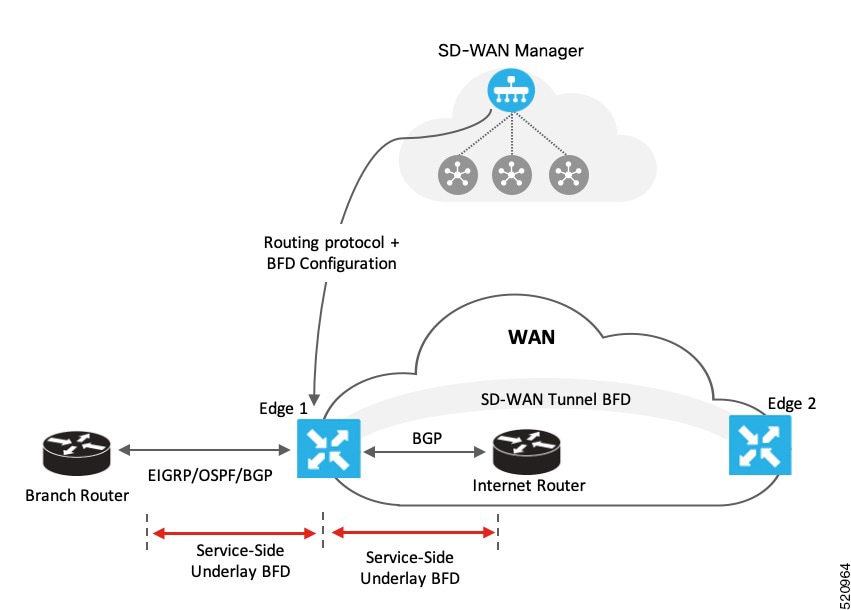
BFD for Routing Protocols in Cisco Catalyst SD-WAN

Cisco IOS XE Catalyst SD-WAN Release 17.3.1a

Cisco vManage Release 20.3.1

This feature extends BFD support to BGP, OSPF, and EIGRP in the Cisco Catalyst SD-WAN solution, allowing BFD to provide a consistent, uniform failure-detection method that quickly identifies forwarding-path failures and enables faster reconvergence.

BFD protocol for Cisco SD-WAN

A Bi-directional Forwarding Detection (BFD) is a network protocol that

  • detects failures rapidly between forwarding engines,

  • operates with low overhead, and

  • enables faster reconvergence of business-critical applications.

BFD provides a single, standardized method to detect link, device, or protocol failures across any layer and media.

BFD in enterprise networks

In enterprise networks, organizations increasingly run business-critical applications on a shared IP infrastructure. They design these networks with high redundancy to protect data and ensure reliability. However, redundancy works effectively only when network devices detect failures and switch to alternate paths quickly.

Traditional protocols often take more than a second to identify failures, which delays recovery for time-sensitive applications. BFD solves this problem by detecting failures rapidly and triggering faster recovery, allowing networks to maintain consistent performance and uptime.

How BFD works in Cisco Catalyst SD-WAN

With this feature, the Cisco Catalyst SD-WAN solution includes two independent BFD types that operate separately without conflict.

BFD Support for Cisco Catalyst SD-WAN Routing Protocols (Legacy BFD): This legacy BFD feature already exists in Cisco IOS XE and extends to the Cisco Catalyst SD-WAN solution starting from Cisco IOS XE Catalyst SD-WAN Release 17.3.1a.

Cisco Catalyst SD-WAN BFD: This feature specifically supports overlay BFD, which already exists in the Cisco Catalyst SD-WAN solution.

This type of BFD detects failures in the overlay tunnel and has these characteristics:

  • It operates by default and cannot be disabled.

  • It typically runs for the Cisco Catalyst SD-WAN Overlay Management Protocol (OMP).

  • In addition to detecting link failures, Cisco Catalyst SD-WAN BFD measures latency, loss, jitter, and other link statistics that application-aware routing uses.

Table 2. Differences: BFD for Cisco Catalyst SD-WAN routing protocols versus Cisco Catalyst SD-WAN BFD
BFD for Cisco Catalyst SD-WAN routing protocols Cisco Catalyst SD-WAN BFD
  • Runs on both, transport-side and service-side interfaces

  • The following protocols can be registered: BGP, OSPF, and EIGRP

    • BGP (transport and service side

    • EIGRP (service side)

    • OSPF and OSPFv3 (service side)

  • Detects link failures for peers in terms of whether a peer is up or down

  • Runs on a Cisco Catalyst SD-WAN tunnel to detect failures in the overlay tunnel

  • Is enabled by default and cannot be disabled

  • Is typically enabled for OMP

  • Besides link failures, it also measures latency, loss, and other link statistics used by application-aware routing

As shown in the image, you configure BFD for a routing protocol through Cisco SD-WAN Manager. Cisco SD-WAN Manager then pushes this configuration to the edge router. In this example, OSPF receives forwarding path detection failure messages from BFD. When a physical link fails, BFD notifies OSPF, prompting it to shut down its neighbors and withdraw or restore any routing information exchanged with remote neighbors.

Similarly, Edge 1 connects to the internet router through its transport interface. You configure BFD for BGP between the transport side of Edge 1 and the internet router. In this setup, BFD monitors the connection’s health and reports any detected failures.

Supported protocols and interfaces

Supported protocols

In Cisco Catalyst SD-WAN, the following routing protocols can receive forwarding-path failure notifications from BFD:

  • BGP

  • EIGRP

  • OSPF

  • OSPFv3

Supported interfaces

BFD supports the following interface types:

  • GigabitEthernet

  • TenGigabitEthernet

  • FiveGigabitEthernet

  • FortyGigabitEthernet

  • HundredGigabitEthernet

  • SVIs

  • Subinterfaces

Restrictions for Cisco IOS XE Catalyst SD-WAN devices in controller mode

  • The device supports only single-hop BFD.

  • The device does not support BFD for static routes.

  • To change the BFD session mode between software and hardware, you must remove all existing BFD configurations and reconfigure them.

  • The device supports BFD only for BGP, EIGRP, OSPF, and OSPFv3.

  • Cisco SD-WAN Manager cannot monitor BFD for routing protocols in Cisco Catalyst SD-WAN; you must use CLI show commands for monitoring.

  • After a BFD session is established, the device does not update BFD session modes (echo-no-echo or software- hardware) immediately when you change BFD template parameters in Cisco SD-WAN Manager; it applies the change only after the session flaps at least once.

Static route support for BFD sessions in transport VPN

For BFD to work correctly, the next-hop IP address must be known and reachable. Static routes configured incorrectly can cause BFD session failures.

Static route configuration guidelines for BFD sessions in transport VPN

  • Do not configure static routes pointing directly to Ethernet (non-P2P) interfaces without specifying a next-hop IP. This causes BFD failures because the next-hop IP is unknown.

  • For Ethernet interfaces using DHCP, ensure the DHCP server provides the router IP. Then use either the DHCP-learned route or configure a static route with the dhcp keyword to dynamically resolve the next-hop IP. For more information on DHCP server and client configurations, see Configuring the Cisco IOS XE DHCP Server and Configuring the Cisco IOS XE DHCP Client.

  • For point-to-point (P2P) interfaces, such as cellular, you can configure static routes that point directly to the interface.

  • In P2P networks, the remote BFD endpoint is always a single hop away with no intermediate devices.

  • In non-P2P networks, the remote BFD endpoint is typically multiple hops away, with the next hop being only the first of several intermediate hops.

Static route support matrix for BFD sessions

Table 3. Static route support matrix for BFD sessions
Exit interface type Static route format BFD support Description

Ethernet (Non-P2P)

ip route 0.0.0.0 0.0.0.0 GigabitEthernetX

Not supported

Next-hop IP unknown; causes BFD failure. Use next-hop IP or DHCP-based static route.

Ethernet (Non-P2P)

ip route 0.0.0.0 0.0.0.0 <next-hop IP>

Supported

Recommended when next-hop IP is static and known.

Ethernet (Non-P2P)

ip route 0.0.0.0 0.0.0.0 dhcp

or

ip route 0.0.0.0 0.0.0.0 GigabitEthernetX dhcp

Supported

For DHCP interfaces; dynamically resolves next-hop IP from DHCP server.

Point-to-Point (P2P)

ip route 0.0.0.0 0.0.0.0 CellularX

Supported

Fully supported static route format for BFD.

Verify static routes for BFD sessions

To verify the installation and next-hop resolution of static default routes regardless of whether the route uses a next-hop IP address, DHCP-resolved next hop, or a directly connected interface use the show ip route command.

Examples

Ethernet (Non-P2P) with multiple next-hop IPs

For these configurations below:

ip route 0.0.0.0 0.0.0.0 10.0.0.1 
ip route 0.0.0.0 0.0.0.0 172.16.0.1

Verify the routing table for transport VPN:

Device# show ip route
S* 0.0.0.0/0 [1/0] via 10.0.0.1
             [1/0] via 172.16.0.1
Device#
Ethernet (Non-P2P) with DHCP-resolved Next-Hop

For this configuration below:

ip route 0.0.0.0 0.0.0.0 dhcp

Verify the routing table for transport VPN:

Device# show ip route
S* 0.0.0.0/0 [1/0] via 192.168.0.1
Device#
Ethernet (Non-P2P) with DHCP on specific interface

For this configuration below:

ip route 0.0.0.0 0.0.0.0 GigabitEthernet0/0/1 dhcp

Verify the routing table for transport VPN:

Device# show ip route
S* 0.0.0.0/0 [1/0] via 192.168.0.1, GigabitEthernet0/0/1
Device#
Point-to-point (P2P) directly connected interface

For this configuration below:

ip route 0.0.0.0 0.0.0.0 Cellular0/0/0

Verify the routing table for transport VPN:

Device# show ip route
S* 0.0.0.0/0 is directly connected, Cellular0/0/0
Device#
Combination of P2P and DHCP-based static routes

For these configurations below:

ip route 0.0.0.0 0.0.0.0 Cellular0/0/0
ip route 0.0.0.0 0.0.0.0 dhcp

Verify the routing table for transport VPN:

Device# show ip route
S* 0.0.0.0/0 is directly connected, Cellular0/0/0
             [1/0] via 192.168.0.1
Device#

Configure BFD using a configuration group

Before you begin

On the Configuration > Configuration Groups page, choose SD-WAN as the solution type.

Procedure


Step 1

From the Cisco SD-WAN Manager menu, choose Configuration > Configuration Groups

Step 2

Create and configure a BFD feature in a System profile.

  1. Configure basic settings.

    Table 4. Basic Configuration

    Field

    Description

    Poll Interval(In Millisecond)

    Specify how often BFD polls all data plane tunnels on a router to collect packet latency, loss, and other statistics used by application-aware routing.

    Range: 1 through 4,294,967,296 (232 – 1) milliseconds

    Default: 600,000 milliseconds (10 minutes)

    Multiplier

    Specify the value by which to multiply the poll interval, to set how often application-aware routing acts on the data plane tunnel statistics to figure out the loss and latency and to calculate new tunnels if the loss and latency times do not meet the configured SLAs.

    Range: 1 through 6

    Default: 6

    DSCP Values for BFD Packets(decimal)

    Specify the Differentiated Services Code Point (DSCP) value of the BFD packets that is used in the DSCP control traffic.

    Range: 0-63

    Default: 48

  2. Configure colors.

    Table 5. Color

    Field

    Description

    Add Color

    Color*

    Choose the color of the transport tunnel for data traffic moving between the devices. The color identifies a specific WAN transport provider.

    Values: 3g, biz-internet, blue, bronze, custom1, custom2, custom3, default, gold, green, lte, metro-ethernet, mpls, private1 through private6, public-internet, red, silver

    Default: default

    Hello Interval (milliseconds)*

    Specify how often BFD sends Hello packets on the transport tunnel. BFD uses these packets to detect the liveness of the tunnel connection and to detect faults on the tunnel.

    Range: 100 through 300000 milliseconds

    Default: 1000 milliseconds (1 second)

    Multiplier*

    Specify how many Hello packet intervals BFD waits before declaring that a tunnel has failed. BFD declares that the tunnel has failed when, during all these intervals, BFD has received no Hello packets on the tunnel. This interval is a multiplier of the Hello packet interval time.

    Range: 1 through 60

    Default: 7

    Path MTU Discovery*

    Enable or disable path MTU discovery for the transport tunnel. When path MTU discovery is enabled, the path MTU for the tunnel connection is checked periodically, about once per minute, and it is updated dynamically. When path MTU discovery is disabled, the expected tunnel MTU is 1472 bytes, but the effective tunnel MTU is 1468 bytes.

    Default: Enabled

    Default DSCP value for BFD packets*

    Specify the Differentiated Services Code Point (DSCP) value of the BFD packets that is used in the DSCP control traffic.

    Range: 0-63

    Default: 48


The show sdwan bfd session output displays BFD parameters based on the negotiation to choose greater value of hello interval and multiplier combined. The calculation of multiplier is changed from the show output per the negotiation result.

What to do next

Also see Deploy a configuration group.

Configure BFD for routing protocols

Use one of these methods to configure BFD for routing protocols:

Configure BFD for routing protocols using templates

Cisco SD-WAN Manager does not provide an independent template to configure BFD for routing protocols. However, you can register or deregister supported protocols to receive BFD packets by adding configurations through the CLI add-on template in Cisco SD-WAN Manager. Use the CLI add-on template to:

  • Add a single-hop BFD template and specify parameters such as timer, multiplier, and session mode.

  • Enable the BFD template under interfaces. You can add only one BFD template per interface.

  • Enable or disable BFD for supported routing protocols. The configuration steps differ for each protocol- BGP, EIGRP, OSPF, and OSPFv3.

Starting with release Cisco IOS XE Catalyst SD-WAN Release 17.15.1a, if SD-WAN mode is not configured for the tunnel interface, the BFDs become inactive for the tunnel interface.

Complete the tasks below to configure BFD for routing protocols using CLI commands.

Enable BFD for routing protocols

Configure BFD for service-side BGP

In Cisco SD-WAN Release 20.7.x and earlier releases, Feature Templates is titled Feature.

Procedure

Step 1

From the Cisco SD-WAN Manager menu, choose Configuration > Templates.

Step 2

Click Feature Templates.

Step 3

Click Add Template.

Step 4

Choose a device from the device list.

Step 5

Choose the CLI Add-on Template under Other Templates.

Step 6

Enter the CLI configuration to create a single-hop BFD template and enable BFD for service-BGP, as shown in the example below.

bfd-template single-hop t1
 interval min-tx 500 min-rx 500 multiplier 3
 !
interface GigabitEthernet1
   bfd template t1 
   
router bgp 10005
address-family ipv4 vrf 1
    neighbor 10.20.24.17 fall-over bfd
    !
  address-family ipv6 vrf 1
    neighbor 2001::7 fall-over bfd

In this example, you create a single-hop BFD template by specifying the minimum interval, maximum interval, and multiplier. These parameters are mandatory. You can also optionally configure other BFD parameters, such as echo mode (enabled by default) and BFD dampening (disabled by default). After creating the template, you enable it under an interface (GigabitEthernet1 in this example).

To modify a BFD template already enabled on an interface, you must first remove the existing template, update it, and then enable it on the interface again.

If you attach the BFD configuration to a device template that already includes a BGP feature template, ensure that you update the BGP configuration in the CLI add-on template to include the no neighbor ip-address ebgp-multihop command. This update is required because the neighbor ip-address ebgp-multihop command is enabled by default in the BGP feature template.

Step 7

Click Save.

Step 8

Attach the CLI Add-on Template with this configuration to the device template.

For the configuration to take effect, the device template must have a BGP feature template attached to it.

Step 9

Attach the device template to the device.


Configure BFD for transport-side BGP

In Cisco SD-WAN Release 20.7.x and earlier releases, Feature Templates is titled Feature.

Procedure

Step 1

From the Cisco SD-WAN Manager menu, choose Configuration > Templates.

Step 2

Click Feature Templates.

Step 3

Click Add Template.

Step 4

Choose a device from the device list.

Step 5

Choose the CLI Add-on Template under Other Templates.

Step 6

Enter the CLI configuration to create a single-hop BFD template and enable BFD for transport-BGP, as shown in the example below.


bfd-template single-hop t1
interval min-tx 500 min-rx 500 multiplier 3
! 
interface GigabitEthernet1
bfd template t1 
!     
router bgp 10005
neighbor 10.1.15.13 fall-over bfd
!
sdwan
interface GigabitEthernet1
tunnel-interface
allow-service bfd
allow-service bgp

In this example, you create a single-hop BFD template by specifying the minimum interval, maximum interval, and multiplier. These parameters are mandatory. You can also configure optional BFD parameters, such as echo mode (enabled by default) and BFD dampening (disabled by default). After creating the template, you enable it under an interface (GigabitEthernet1 in this example), because GigabitEthernet1 is also the SD-WAN tunnel source, allowing service under its tunnel interface ensures that both BGP and BFD packets pass over the tunnel.

To modify a BFD template already enabled on an interface, you must remove the existing template, update it, and then enable it on the interface again.

If you attach the BFD configuration to a device template that already includes a BGP feature template, ensure that you update the BGP configuration in the CLI add-on template to include the no neighbor ip-address ebgp-multihop command. This update is required because the neighbor ip-address ebgp-multihop command is enabled by default in the BGP feature template.

Step 7

Click Save.

Step 8

Attach the CLI Add-on Template with this configuration to the device template.

For the configuration to take effect, the device template must have a BGP feature template attached to it.

Step 9

Attach the device template to the device.


Configure BFD for service-side EIGRP

In Cisco SD-WAN Release 20.7.x and earlier releases, Feature Templates is titled Feature.

Procedure

Step 1

From the Cisco SD-WAN Manager menu, choose Configuration > Templates.

Step 2

Click Feature Templates.

Step 3

Click Add Template.

Step 4

Choose a device from the device list.

Step 5

Choose the CLI Add-on Template under Other Templates.

Step 6

Enter the CLI configuration to add a single-hop BFD template and enable BFD for EIGRP as shown in the example below.

bfd-template single-hop t1
 interval min-tx 500 min-rx 500 multiplier 3
 !
interface GigabitEthernet5
   bfd template t1 
   
router eigrp myeigrp
address-family ipv4 vrf 1 autonomous-system 1
    af-interface GigabitEthernet5
     bfd

In this example, you create a single-hop BFD template by specifying the minimum interval, maximum interval, and multiplier. These parameters are mandatory. You can also configure optional BFD parameters, such as echo mode (enabled by default) and BFD dampening (disabled by default).

After creating the template, you enable it under an interface (GigabitEthernet5 in this example).

To modify a BFD template already enabled on an interface, you must first remove the existing template, update it, and then enable it on the interface again.

Step 7

Click Save.

Step 8

Attach the CLI Add-on Template with this configuration to the device template.

For the configuration to take effect, the device template must have a BGP feature template attached to it.

Step 9

Attach the device template to the device.


Configure BFD for service-side OSPF and OSPFv3

In Cisco SD-WAN Release 20.7.x and earlier releases, Feature Templates is titled Feature.

Procedure

Step 1

From the Cisco SD-WAN Manager menu, choose Configuration > Templates.

Step 2

Click Feature Templates.

Step 3

Click Add Template.

Step 4

Choose a device from the device list.

Step 5

Choose the CLI Add-on Template under Other Templates.

Step 6

Enter the CLI configuration to add a single-hop BFD template enable BFD for OSPF and OSPFv3 as shown in the examples below.

OSPF
bfd-template single-hop t1
interval min-tx 500 min-rx 500 multiplier 3
! 
interface GigabitEthernet5
bfd template t1
!
interface GigabitEthernet1
bfd template t1 
!     
router ospf 1 vrf 1
 bfd all-interfaces
!
OSPFv3
bfd-template single-hop t1
 interval min-tx 500 min-rx 500 multiplier 3
 
interface GigabitEthernet5
   bfd template t1
router ospfv3 1
 address-family ipv4 vrf 1
  bfd all-interfaces

In these examples, you create a single-hop BFD template by specifying the minimum interval, maximum interval, and multiplier. These parameters are mandatory. You can also configure optional BFD parameters, such as echo mode (enabled by default) and BFD dampening (disabled by default).

After creating the template, you enable it under an interface (GigabitEthernet5 in this example).

To modify a BFD template already enabled on an interface, you must first remove the existing template, update it, and then enable it on the interface again.

Step 7

Click Save.

Step 8

Attach the CLI Add-on Template with this configuration to the device template.

For the configuration to take effect, the device template must have a BGP feature template attached to it.

Step 9

Attach the device template to the device.


Attach feature template to device template

Use these steps to attach the configuration to a device template.

After you create a CLI add-on template to enable BFD, attach the template to the device template for the configuration to take effect.

In Cisco SD-WAN Release 20.7.x and earlier releases, Device Templates is titled Device.

Before you begin

Make sure the device template already includes the relevant feature template (BGP, OSPF, or EIGRP) before you attach the CLI add-on template.

Procedure

Step 1

From the Cisco SD-WAN Manager menu, choose Configuration > Templates.

Step 2

Click Device Templates.

Step 3

Click Create Template and choose From Feature Template from the drop-down options.

Step 4

From the Device Model drop-down options, choose a device.

Enter a name and description for the template.

Step 5

Click Create.

Step 6

Click Additional Templates.

Step 7

In the CLI Add-on Template field, choose the CLI add-on template you configured to enable BFD for routing protocols.

Step 8

Click Create.


What to do next

Attach device template to device

Configure BFD for routing protocols using CLI commands

Follow these steps to configure BFD for BGP, EIGRP, OSPF, and OSPF3 using device CLI.

Procedure


Step 1

Create a BFD template.

The CLI configuration for creating a BFD template remains the same irrespective of the protocol you configure it for.

Create a single-hop BFD template as shown in the example below.

bfd-template single-hop t1
 interval min-tx 500 min-rx 500 multiplier 3 

Step 2

Enable BFD for service-side BGP.

This example shows BGP configured, BFD enabled on the interface under VRF 1, and then enabled for service-side BGP.

interface GigabitEthernet5
bfd template t1
!                 
router bgp 10005
  bgp log-neighbor-changes
  distance bgp 20 200 20
  !
  address-family ipv4 vrf 1
  bgp router-id 10.20.24.15
  redistribute connected
  neighbor 10.20.24.17 remote-as 10007
  neighbor 10.20.24.17 activate
  neighbor 10.20.24.17 send-community both
  neighbor 10.20.24.17 maximum-prefix 2147483647 100
  neighbor 10.20.24.17 fall-over bfd
  exit-address-family
  !
  address-family ipv6 vrf 1
  bgp router-id 10.20.24.15
  neighbor 2001::7 remote-as 10007
  neighbor 2001::7 activate
  neighbor 2001::7 send-community both
  neighbor 2001::7 maximum-prefix 2147483647 100
  neighbor 2001::7 fall-over bfd
  exit-address-family

Step 3

Enable BFD for transport-side BGP

interface GigabitEthernet1
bfd template t1
!                 
router bgp 10005
bgp router-id   10.1.15.15
bgp log-neighbor-changes
distance bgp 20 200 20
neighbor 10.1.15.13 remote-as 10003
neighbor 10.1.15.13 fall-over bfd
address-family ipv4 unicast
neighbor 10.1.15.13 remote-as 10003
neighbor 10.1.15.13 activate
neighbor 10.1.15.13 maximum-prefix 2147483647 100
neighbor 10.1.15.13 send-community both
redistribute connected
exit-address-family
!
timers bgp 60 180

sdwan
interface GigabitEthernet1
tunnel-interface
allow-service bgp
allow-service bfd

Step 4

Enable BFD for EIGRP.

This example shows EIGRP configured, BFD enabled on the interface under VRF 1, and then enabled for service-side EIGRP.

interface GigabitEthernet5
bfd template t1
!
router eigrp myeigrp
address-family ipv4 vrf 1 autonomous-system 1
    af-interface GigabitEthernet5
     no dampening-change
     no dampening-interval
     hello-interval 5
     hold-time      15
     split-horizon
     bfd
     exit-af-interface
    !
    network 10.20.24.0 0.0.0.255
    topology base
     redistribute connected
     redistribute omp
     exit-af-topology
    !
    exit-address-family
   !

Step 5

Enable BFD for OSPFv3.

This example shows OSPFv3 configured, BFD enabled on the interface under VRF 1, and then enabled for service-side OSPFv3.

interface GigabitEthernet5
   bfd template t1
   ospfv3 1 ipv4 area 0
   ospfv3 1 ipv4 dead-interval 40
   ospfv3 1 ipv4 hello-interval 10
   ospfv3 1 ipv4 network broadcast
   ospfv3 1 ipv4 priority 1
   ospfv3 1 ipv4 retransmit-interval 5
   ospfv3 1 ipv6 area 0
   ospfv3 1 ipv6 dead-interval 40
   ospfv3 1 ipv6 hello-interval 10
   ospfv3 1 ipv6 network broadcast
   ospfv3 1 ipv6 priority 1
   ospfv3 1 ipv6 retransmit-interval 5
  
router ospfv3 1
 address-family ipv4 vrf 1
  area 0 normal
  bfd all-interfaces
  router-id 10.20.24.15
  distance 110
  exit-address-family
 !
 address-family ipv6 vrf 1
  area 0 normal
  bfd all-interfaces
  router-id 10.20.24.15
  distance 110
  exit-address-family
 !
!
exit

Automatically suspending BFD sessions

A BFD session flap is a network condition that

  • occurs when a BFD session repeatedly transitions between up and down states,

  • happens because one device in the session becomes unavailable and then available again, or

  • repeatedly recovers and fails due to unstable connections, disrupting applications and causing unnecessary traffic steering between overlay paths.

Automatically suspending BFD sessions

To prevent repeated BFD session flaps, Cisco Catalyst SD-WAN automatically suspends unstable BFD sessions based on the following parameters:

Flap cycle

A flap cycle includes this sequence:

  • The BFD session is in the up state.

  • The BFD session transitions to the down state.

  • The BFD session comes back up.

SLA threshold

An SLA threshold determines when to add a BFD session to the suspended list. It defines a limit for traffic metrics such as loss, latency, or jitter. When any metric exceeds the defined threshold, the system suspends the BFD session. These thresholds represent the traffic performance levels specified in the SLA.

An SLA threshold is optional. If you configure one, set higher values for loss, latency, and jitter to prevent conflicts with SLA parameters defined in SLA classes. For more details on SLA classes, see the Cisco Catalyst SD-WAN Policies Configuration Guide.

Benefits of automatically suspending BFD sessions

  • You can manually remove the affected circuit or tunnel interface from the BFD suspended list.

  • Provides monitoring of a suspended tunnel.

How BFD session suspension works

  • As the BFD suspension feature is for forward data traffic, you should enable BFD suspension on the remote-end node to block the reverse data traffic to avoid dropping data traffic.

  • This feature does not manipulate the state of the BFD session.

Summary

The BFD session suspension workflow temporarily halts unstable sessions to prevent repeated flapping, allowing only control traffic while blocking data traffic until stability is restored.

Workflow

If a BFD session exceeds the flap-count value within the configured flapping-window interval, then the BFD session must remain suspended until the configured duration interval.

  1. For a BFD session in the suspended state, the following occurs:
    • If a session reflaps or exceeds the threshold parameters defined, the session is moved back to suspended state and the duration is reset again.
    • If the session does not flap and is within the threshold range, the session is automatically removed out of the suspended state after the duration interval expires.
    • You can also manually remove suspended BFD sessions by using the request platform software sdwan auto-suspend reset command. For more information, see the Cisco IOS XE SD-WAN Qualified Command Reference Guide.

Result

Data traffic is not sent across the overlay network when a BFD session is in the suspended state.

Only regular SLA measurement, echo response, or path maximum transmission unit (PMTU) control traffic is sent across a suspended BFD session.

Restrictions for automatically suspending BFD sessions

Defines limitations for using BFD automatic suspension in Cisco SD-WAN.

  • On a Cisco IOS XE Catalyst SD-WAN device with a single TLOC, automatic suspension may drop BFD sessions.

  • The last-resort circuit may not work for a single site unless all BFD sessions are down for a tunnel interface. The last-resort circuit is enabled only if all BFD sessions on the non last-resort circuit are suspended or down.

  • SD-WAN Manager feature templates do not support configuring automatic suspension of BFD sessions.

  • You can configure BFD automatic suspension only through a device CLI or a CLI add-on template.

  • When duplicated traffic is sent through a different BFD session, it may still route through a suspended BFD session.

Configure automatic suspension of BFD sessions using a CLI template

To configure automatic suspension of BFD sessions using a CLI template.

If you enable color all and a specific color , the specific color takes precedence over the color all parameter. For more information on BFD colors, see bfd color.

For more information about using CLI templates, see CLI Add-On Feature Templates and CLI Templates.

Procedure


Step 1

Enable BFD automatic suspension with or without last resort.

Before enabling last resort for the BFD automatic suspension feature, you must enable the last-resort circuit on a tunnel interface.

For more information on last resort, see last-resort-circuit.

auto-suspend
    enable-lr
auto-suspend
    no enable-lr

Step 2

Configure the flap parameters.

When you use SLA-based BFD automatic suspension, ensure the duration is greater than the BFD multiplier multiplied by the BFD poll interval. We recommend configuring the BFD automatic suspension duration to more than 30 minutes.

duration sec
    flapping-window sec
    flap-count flap-count

Step 3

(Optional) Configure SLA parameters.

Before configuring SLA thresholds, ensure to configure BFD session flapping parameters and duration.

thresholds
   color
    all
     jitter  jitter-value
     latency latency-value
     loss    loss-value
    !

Verify automatic suspension of BFD sessions

Use any of these commands to verify automatic suspension of BFD sessions.

To view the total suspend count and check how many times the BFD session has been suspended, use the show sdwan bfd sessions suspend command.

The following columns are added for analyzing BFD session suspension metrics: RE-SUSPEND COUNT, SUSPEND TIME LEFT, TOTAL COUNT, and SUSPEND DURATION.

Device# show sdwan bfd sessions suspend
                          SOURCE TLOC   REMOTE TLOC                    DST PUBLIC       DST PUBLIC         RE-SUSPEND  SUSPEND       TOTAL     SUSPEND
SYSTEM IP        STATE    COLOR         COLOR           SOURCE IP      IP               PORT        ENCAP  COUNT       TIME LEFT     COUNT     DURATION
---------------------------------------------------------------------------------------------------------------------------------------------------------
172.16.255.14    up       lte           lte             10.1.15.15     10.1.14.14       12426       ipsec   0          0:00:19:52    18        0:00:00:07

To check whether a suspended flag has been added to a BFD session and to view other BFD session metrics, use the show sdwan bfd sessions alt command.

The following columns are added for BFD suspension:

  • BFD-LD (Local Discriminator) is a unique identifier for all BFD sessions. Its value must be non-zero and is used internally by Cisco TAC for troubleshooting.

  • The FLAGS column includes the ‘Sus’ flag, which indicates that a BFD session is suspended.”

Device# show sdwan bfd sessions alt
*Sus = Suspend
*NA  = Flag Not Set
                                       SOURCE TLOC    REMOTE TLOC                  DST PUBLIC      DST PUBLIC
SYSTEM IP        SITE ID   STATE       COLOR          COLOR          SOURCE IP     IP              PORT        ENCAP  BFD-LD    FLAGS    UPTIME
-----------------------------------------------------------------------------------------------------------------------------------------------------
172.16.255.14    400       up          3g              lte           10.0.20.15    10.1.14.14      12426       ipsec  20004     NA       0:19:30:40
172.16.255.14    400       up          lte             lte           10.1.15.15    10.1.14.14      12426       ipsec  20003     Sus      0:00:02:46
172.16.255.16    600       up          3g              lte           10.0.20.15    10.0.106.1      12366       ipsec  20002     NA       0:19:30:40
172.16.255.16    600       up          lte             lte           10.1.15.15    10.0.106.1      12366       ipsec  20001     NA       0:19:20:14

To view the BFD sessions where the ‘Sus’ flag is added, use the show sdwan bfd history command.

Device# show sdwan bfd history
                                                   DST PUBLIC       DST PUBLIC                                RX      TX
SYSTEM IP        SITE ID     COLOR     STATE       IP               PORT        ENCAP  TIME                   PKTS    PKTS    DEL   FLAGS
------------------------------------------------------------------------------------------------------------------------------------------
172.16.255.16    600         lte       up          10.0.106.1       12366       ipsec  06/03/22 02:51:06      0       0       0     [ ]
172.16.255.16    600         lte       up          10.0.106.1       12366       ipsec  06/03/22 02:52:04      153     154     0     [Sus]
172.16.255.16    600         lte       down        10.0.106.1       12366       ipsec  06/03/22 03:00:50      1085    1085    0     [Sus]

To view a summary of BFD sessions, including sessions that are up, down, have flapped, or have been suspended use the show sdwan bfd summary command.

The following fields are added for BFD session suspension: sessions-flap, sessions-up-suspended, and sessions-down-suspended.

Device# show sdwan bfd summary
sessions-total           4
sessions-up              4
sessions-max             4
sessions-flap            4
poll-interval            60000
sessions-up-suspended    1
sessions-down-suspended  0

Monitor and verify BFD configuration

This sections provides a list of commands that you can run to verify your BFD configuration.

Verify the BFD template

Run the show bfd interface command to check the BFD template under an interface.


Device# show bfd interface
Interface Name: GigabitEthernet5
 Interface Number: 11
 Configured bfd interval using bfd template: 12383_4T1
 Min Tx Interval: 50000, Min Rx Interval: 50000, Multiplier: 3
Verify BFD configuration for BGP

Run the show bfd neighbors client bgp ipv4 command to check the status of the BFD session.


Device# show bfd neighbors client bgp ipv4

IPv4 Sessions
NeighAddr                              LD/RD         RH/RS     State     Int
10.20.24.17                             1/1          Up        Up        Gi5
Verify BFD configuration for EIGRP

Run the show bfd neighbors client eigrp command to check the status of the BFD session.


Device# show bfd neighbors client eigrp
IPv4 Sessions
NeighAddr                              LD/RD         RH/RS     State     Int
10.20.24.17                             1/1          Up        Up        Gi5
Verify BFD configuration for OSPF

Run the show bfd neighbors client ospf command to check the status of the BFD session.


Device# show bfd neighbors client ospf
IPv4 Sessions
NeighAddr            LD/RD         RH/RS     State     Int
10.20.24.17          1/1          Up        Up        Gi5

Troubleshoot common BFD errors

This section explains how to identify and resolve common BFD issues.

Check control connections

If you experience issues with BFD, start by checking the control connection between Cisco SD-WAN Manager and the edge router by running the show sdwan control connections command.

Device#show sdwan control connections 
                                                                                       PEER                                          PEER                                          CONTROLLER 
PEER    PEER PEER            SITE       DOMAIN PEER                                    PRIV  PEER                                    PUB                                           GROUP      
TYPE    PROT SYSTEM IP       ID         ID     PRIVATE IP                              PORT  PUBLIC IP                               PORT  LOCAL COLOR     PROXY STATE UPTIME      ID         
----------------------------------------------------------------------------------------------------------------------------------------------------------------------------------------
vsmart  dtls 172.16.255.19   100        1      10.0.5.19                               12355 10.0.5.19                               12355 lte             No    up     0:12:45:44  0           
vsmart  dtls 172.16.255.20   200        1      10.0.12.20                              12356 10.0.12.20                              12356 lte             No    up     0:15:59:45  0           
vmanage dtls 172.16.255.22   200        0      10.0.12.22                              
Issues in pushing device template to device

If you identify issues with pushing the device template to the device, collect debug logs on the edge device as shown below.

debug netconf all
request platform soft system shell
tail -f /var/log/confd/cia-netconf-trace.log

If Cisco SD-WAN Manager has successfully pushed the configuration to the device and the issue still persists, run the show sdwan running-config command to view all details related to BFD.

Issues with transport-side BFD

If the transport-side BFD session is down, check the packet filter data under the Cisco Catalyst SD-WAN tunnel interface to ensure that you have allowed the BFD packets to pass through on the transport side. Look for allow-service bgp and allow-service bfd in the output.

Device#show sdwan running-config  | sec sdwan
 tunnel mode sdwan
sdwan
 interface GigabitEthernet1
  tunnel-interface
   encapsulation ipsec
   color lte
   allow-service bgp
   allow-service bfd
   ……………

Troubleshoot BFD using radioactive tracing

Minimum supported releases: Cisco IOS XE Catalyst SD-WAN Release 17.15.1a and Cisco Catalyst SD-WAN Manager Release 20.15.1

BFD troubleshooting focuses on identifying and fixing issues in the BFD protocol, which detects faults between devices. You can use this feature to check device logs and run debugging commands to collect detailed information about BFD activity.

Radioactive tracing helps in selective debugging of a session. Tracing is enabled across the layers for intended BFD session that is identified by tloc-pair or a local discriminator. It enables debug level traces automatically for all the modules while processing a packet that matches the condition.

The following show and debug commands are used in BFD troubleshooting:

  • debug platform condition start

  • debug platform condition feature sdwan controlplane bfd

  • show platform hardware qfp active feature bfd datapath

  • show logging profile sdwan internal filter

For more information on these show commands, see the chapter Troubleshooting Commands in the Cisco IOS XE SD-WAN Qualified Command Reference guide.