Multicast Overlay Routing

Feature history for multicast overlay

This table describes the developments of this feature, by release.

Table 1. Feature history
Feature Name Release Information Description

Support for multicast overlay routing Protocols

Cisco IOS XE Catalyst SD-WAN Release 17.2.1r

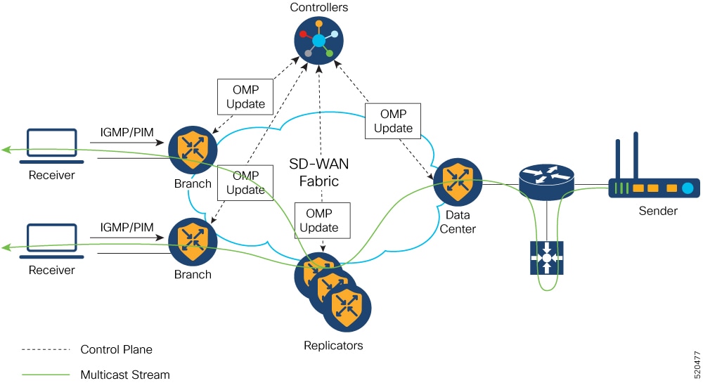
This feature enables efficient distribution of one-to-many traffic. Multicast routing protocols such as IPv4 Multicast, IGMPv3, PIM SSM, PIM ASM, Auto RP, and Static RP distribute data, such as audio or video streaming broadcasts, to multiple recipients.

Using multicast overlay protocols, a source can send a single packet of data to a single multicast address, which is then distributed to an entire group of recipients.

Multicast over L3 TLOC extension

Cisco IOS XE Catalyst SD-WAN Release 17.3.2

Cisco SD-WAN Release 20.3.1

This feature enables support for transport location (TLOC), which allows addition of the peer’s transport to avoid the extra cost of additional IP addresses. It also allows dynamic load balancing across multiple transports.

Dynamic rendezvous point (RP) selection by a PIM BSR

Cisco IOS XE Catalyst SD-WAN Release 17.5.1a

Cisco SD-WAN Release 20.5.1

This feature adds support for automatic selection of an RP candidate using a PIM BSR in an IPv4 multicast overlay. There is no single point of failure because every site has a local RP.

A Cisco IOS XE Catalyst SD-WAN device device is selected as the RP, not a service-side device.

Support for MSDP to interconnect Cisco SD-WAN and non-SD-WAN domains

Cisco IOS XE Catalyst SD-WAN Release 17.11.1a

Cisco Catalyst SD-WAN Control Components Release 20.11.1

This feature enables Multicast Source Discovery Protocol (MSDP) interoperability between Cisco IOS XE Catalyst SD-WAN devices in Cisco Catalyst SD-WAN and the devices in a non-SD-WAN setup.

Note


This feature does not provide support for MSDP peers formed between Cisco IOS XE Catalyst SD-WAN devices in the overlay network.

Multicast support for hub and spoke topologies

Cisco IOS XE Catalyst SD-WAN Release 17.15.1a

Cisco Catalyst SD-WAN Manager Release 20.15.1

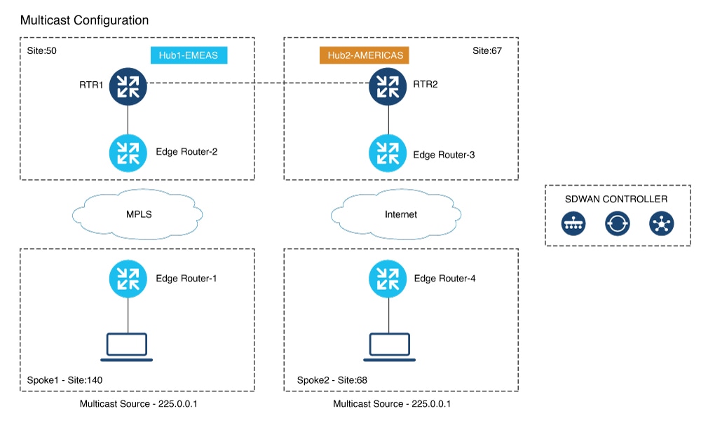
This feature enables efficient distribution of traffic on edge devices using hub-and-spoke network topology. Multicast routing protocols such as IPv4 Multicast, IGMPv3, PIM SSM, PIM ASM, Auto RP, and Static RP distribute data to multiple recipients.

Multicast overlay routing for Cisco IOS XE Catalyst SD-WAN

A Cisco IOS XE Catalyst SD-WAN multicast overlay is a routing protocol that:

  • extends Protocol Independent Multicast Source-Specific Multicast (PIM-SSM) over the Cisco Catalyst SD-WAN overlay using Overlay Management Protocol (OMP),

  • integrates PIM-SM in customer VPNs with OMP in the overlay, leverages Cisco IOS XE MVPN, and uses OMP replicators to optimize the multicast distribution tree across the overlay topology, and

  • supports IGMPv2 and IGMPv3 reports, advertising receiver multicast interest to remote Cisco Catalyst SD-WAN routers using OMP and enabling dynamic join or prune actions for optimized and secure multicast delivery over the overlay network.

The Cisco IOS XE Catalyst SD-WAN multicast overlay implementation extends native multicast by creating a secure optimized multicast tree that runs on top of the overlay network.

Protocol Independent Multicast Sparse-Mode (PIM-SM) is deployed in the customer VPNs, and the OMP replicator is used in overlay multicast to optimize the multicast distribution tree.

The Cisco IOS XE Catalyst SD-WAN router advertises receiver's multicast interest using OMP and participates in join or prune actions with replicators, which use OMP to relay these actions to routers providing overlay connectivity to the PIM-RP or source.

Multicast overlay supported features


Note


From Cisco IOS XE Catalyst SD-WAN Release 17.3.2, TLOC extension with multicast and multicast application-aware route policy features are supported.


  • IPv4 Overlay Multicast (PIM SSM), IPv4 Overlay Multicast (PIM ASM)

  • PIM-RP on IOS XE VPN

  • Replicator with geo-location (GPS)

  • Static RP and Auto-RP

  • PIM Bootstrap Router (BSR)

  • IGMP v2, IGMP v3, and PIM on service side

  • IPSec and GRE Encapsulation

  • vEdge and IOS XE Catalyst SD-WAN Interop

  • Overlay Multicast Signaling using OMP

Restrictions for multicast overlay routing

Multicast overlay routing does not support these features:

  • MSDP/Anycast-RP on Cisco Catalyst SD-WAN routers.

  • IPv6 overlay and IPv6 underlay.

  • Dynamic BFD tunnel for multicast.

  • Multicast with asymmetric unicast routing.

  • Multicast overlay working does not support Data Policy. If a data policy is configured, only the required traffic is matched and multicast traffic is not matched.

  • The Cisco vEdge device is used only as the Last Hop Router (LHR), whereas Cisco IOS XE Catalyst SD-WAN devices can be used in all multicast roles (FHR, LHR, RP and Replicator roles).

  • Bidirectional PIM is not supported with hub-and-spoke or full-mesh deployments.

  • On Cisco 1000 Series Integrated Services Routers, when IGMP snooping is enabled and there are no local receivers for multicast traffic in the VLAN, the multicast traffic floods to all ports in the VLAN.

Restrictions for multicast routing with hub-and-spoke topology

Minimum supported releases: Cisco IOS XE Catalyst SD-WAN Release 17.15.1a and Cisco Catalyst SD-WAN Manager Release 20.15.1.

  • You can configure multicast rendezvous point and replicator node on hub-site devices only. Replicator cannot be configured on spoke-site devices.

  • MSDP interconnect feature is not supported with hub-and-spoke multicast deployment.

  • You can configure multicast routing on hub-and-spoke using CLI add-on template only.

  • On-demand tunnel between spoke sites is not supported with multicast.

  • Multicast is supported only with centralized control policy–based hub-and-spoke deployment. Intent-based configuration, as described in the Hub-and-Spoke chapter, is not supported.

Configure multicast overlay routing

Prerequisites:

  1. If you want to limit rendezvous point (RP) selection, configure an IPv4 ACL using a CLI add-on template. Configure an IPv4 ACL using a standard or extended access list and attach it to your device before enabling PIM.

    You must have created a valid standard or extended ACL prior to using the ACL in your multicast configuration.

  2. If you want to limit rendezvous point (RP) selection, configure an IPv4 ACL using a CLI add-on template. Configure an IPv4 ACL using a standard or extended access list and attach it to your device before enabling PIM.

  3. You cannot configure an ACL for a PIM feature template using Cisco SD-WAN Manager. You must configure the ACL using a CLI add-on template. The Cisco IOS XE Catalyst SD-WAN multicast overlay implementation supports IOS XE standard or extended access lists.

  4. At least one replicator is mandatory for overlay multicast configuration.

  5. You can optionally configure IGMP to allow individual hosts on the service side to join multicast groups within a particular VPN.

Configure multicast using configuration groups

From Cisco IOS XE Catalyst SD-WAN Release 17.11.1a you have the option to configure multicast using Configuration Groups.

Procedure


Step 1

From the Cisco SD-WAN Manager menu, choose Configuration > Templates > Configuration Groups.

Step 2

Click adjacent to the configuration group name and choose Edit.

Step 3

Click Service Profile.

Step 4

Click Add Feature.

Step 5

From the feature drop-down list, choose Multicast.

The Cisco IOS XE Catalyst SD-WAN overlay multicast network supports the following protocols:

  • PIM

  • IGMP

  • MSDP

The following tables describe the options for configuring the Multicast feature.

Field

Description

Type

Choose a feature from the drop-down list.

Feature Name*

Enter a name for the feature.

Description

Enter a description of the feature. The description can contain any characters and spaces.

Table 2. Basic Configuration

Field

Description

SPT Only

Enable this option to ensure that the Rendezvous Points (RPs) can communicate with each other using the shortest-path tree.

Local Replicator

Enable this option to configure the Cisco IOS XE Catalyst SD-WAN device as a multicast replicator.

Threshold

Specify a value.

Optional, keep it set to the default value if you are not configuring a replicator.

Table 3. PIM

Field

Description

Source Specific Multicast (SSM)

Enable this option to configure SSM.

ACL

Specify an access control list value. An access control list allows you to filter multicast traffic streams using the group and sometimes source IPv4 or IPv6 addresses.

Configure an IPv4 access control list using a standard or extended access list and attach it to your device before enabling PIM. You must have created a valid standard or extended ACL before using the ACL in your multicast configuration.

Note


You cannot configure an ACL for a PIM feature template using Cisco SD-WAN Manager. You must configure the ACL using a CLI add-on template. For information on configuring ACL using the CLI add-on template, see the section Configure an ACL for Multicast Using a CLI Add-On Template in chapter Multicast Overlay Routing of the Cisco SD-WAN Routing Configuration Guide.

SPT Threshold

Specify the traffic rate, in kbps, at which to switch from the shared tree to the shortest-path tree (SPT). Configuring this value forces traffic to remain on the shared tree and travel via the RP instead of via the SPT.

Add Interface

Interface Name

Enter the name of an interface that participates in the PIM domain, in the format ge slot /port.

Query Interval(sec)

Specify how often the interface sends PIM query messages. Query messages advertise that PIM is enabled on the router.

Join/Prune Interval(sec)

Specify how often PIM multicast traffic can join or be removed from a rendezvous point tree (RPT) or shortest-path tree (SPT). Cisco IOS XE Catalyst SD-WAN device send join and prune messages to their upstream RPF neighbor.

How do you want to configure your Rendezvous Point (RP)

Cisco IOS XE SD-WAN supports the following modes:

Static

Click this check box to a specify the static IP address of a rendezvous point (RP).

Add Static RP

IP Address

Specify the static IP address of a rendezvous point (RP).

ACL

Specify an ACL value.

Override

Enable this option for cases when dynamic and static group-to-RP mappings are used together and there is an RP address conflict. In this case, the RP address configured for a static group-to-RP mapping takes precedence.

If you do not enable this option, and there is RP address conflict, dynamic group-to-RP mappings will take precedence over static group-to-RP mappings.

Auto RP

Click this check box to enable reception of PIM group-to-RP mapping updates. This enables reception on the Auto-RP multicast groups, 224.0.1.39 and 224.0.1.40.

RP Announce

Click this check box to enable transmission of Auto-RP multicast messages.

RP Discovery

Click this check box to enable Auto-RP automatic discovery of rendezvous points (RPs) in the PIM network so that the router can serve as an Auto-RP mapping agent. An Auto-RP mapping receives all the RPs and their respective multicast groups and advertise consistent group-to-RP mapping updates.

Interface

Specify the source interface for Auto-RP RP Announcements or RP Discovery messages.

Scope

Specify the IP header Time-to-Live (TTL) for Auto-RP RP Announcements or RP Discovery messages.

PIM-BSR

Configure a PIM BSR.

RP Candidate

Interface Name

Choose the interface that you used for configuring the PIM feature template.

Access List

Add an access list value if you have configured the access list with a value.

Interval

Add an interval value if you have configured the interval with a value.

Priority

Specify a higher priority on the Cisco IOS XE SD-WAN device than on the service-side device.

BSR Candidate (Maximum: 1)

Interface Name

Chose the same interface from the drop-down list that you used for configuring the PIM feature template.

Hash Mask Length

Specify the hash mask length. Valid values for hash mask length are 0–32.

Priority

Specify a higher priority on the Cisco IOS XE Catalyst SD-WAN device than on the service-side device.

RP Candidate Access List

Add a value if you have configured the RP candidate access list with a value.

An RP candidate uses a standard ACL where you can enter the name for the access list.

Table 4. IGMP

Field

Description

Add IGMP

Interface

Enter the name of the interface to use for IGMP. To add another interface, click Add.

Version

Specify a version number.

Optional, keep it set to the default version number.

Group Address

Enter a group address to join a multicast group.

Source Address

Enter a source address to join a multicast group.

Add

Click Add to add the IGMP for the group.

Table 5. MSDP

Field

Description

Originator-ID

Specify the ID of the originating device. This ID is the IP address of the interface that is used as the RP address.

Connection Retry Interval

Configure an interval at which MSDP peers will wait after peering sessions are reset before attempting to re-establish the peering sessions.

Mesh Group

Mesh Group Name

Enter a mesh group name. This configures an MSDP mesh group and indicates that an MSDP peer belongs to that mesh group.

Note


All MSDP peers present on a device that participate in a mesh group must be in a full mesh with all other MSDP peers in the group. Each MSDP peer on each device must be configured as a peer using the ip msdp peer command, and as a member of the mesh group using the ip msdp mesh-group command.

Peer-IP

Configure an MSDP peer specified by an IP address.

Advanced Settings

Connect-Source Interface

Enter the primary address of a specified local interface that is used as the source IP address for the TCP connection.

Peer Authentication Password

Enables MD5 password encryption for a TCP connection between two MSDP peers.

Note


MD5 authentication must be configured with the same password on both MSDP peers. Otherwise, a connection between them cannot be established.

Keep Alive

Configure an interval at which an MSDP peer will send keepalive messages.

Hold-Time

Configure an interval at which the MSDP peer will wait for keepalive messages from other peers before declaring them as down.

Remote AS

Specifies the autonomous system number of the MSDP peer. This keyword and argument are used for display purposes only.

SA Limit

Limits the number of SA messages allowed in the SA cache from the specified MSDP.

Default Peer

Configure a default peer from which to accept all MSDP SA messages.


Configure multicast using the CLI

To configure multicast, excute this command:

Procedure


sdwan multicast address-family ipv4 vrf 1 replicator [threshold <num>]

Example:

Device(config)# sdwan
Device(config)# multicast
  Device(config)# address-family ipv4 vrf 1
  Device(config)# replicator threshold 7500
  Device(config)# !
 !

Configure multicast using Cisco SD-WAN Manager

When a Cisco IOS XE Catalyst SD-WAN router is used as a replicator, follow these steps to configure multicast:

Procedure


Step 1

From the Cisco SD-WAN Manager menu, choose Configuration > Templates .

Step 2

Click Device Templates.

Step 3

From the Create Template drop-down list, choose From Feature Template. From the Device Model drop-down list, choose the type of device for which you are creating the template.

Step 4

Click Service VPN in the Service VPN section. Click the Service VPN drop-down list.

Step 5

Under Additional VPN Templates, click Multicast.

Step 6

To enable Local Replicator on the device, choose On (otherwise keep it Off).

Step 7

To configure replicator, choose the Threshold. (Optional, keep it default if you are not configuring replicator).

Step 8

Save feature template. Attach feature template to device template.

Step 9

In the Template Description field, enter a description of the template. The description can be up to 2048 characters and can contain only alphanumeric characters.


What to do next

When you first open a feature template, for each parameter that has a default value, the scope is set to Default (indicated by a check mark), and the default setting or value is shown. To change the default or to enter a value, click the scope drop-down list to the left of the parameter field and select the value.

Configure an ACL for multicast using a CLI Add-On template

You can configure an ACL to limit RP and Bootstrap Router (BSR) selection using a CLI add-on template. An ACL allows you to filter multicast traffic streams using the group and sometimes source IPv4 or IPv6 addresses.

Before you begin

Once you create the CLI add-on template, you attach it to the device.

Procedure


Step 1

To configure an ACL for multicast, create a CLI add-on feature template and attach it to the device template.

Example:

ip access-list standard 27
1 permit 225.0.0.0 0.255.255.255
2 permit 226.0.0.0 0.255.255.255
3 permit 227.0.0.0 0.255.255.255
4 permit 228.0.0.0 0.255.255.255
5 deny 229.0.0.0 0.255.255.255
6 permit any
ip access-list extended 101
1 permit pim 172.16.10.0 0.0.0.255 any
2 permit pim 10.1.1.0 0.0.0.255 any

Step 2

From the Configuration > Templates window, choose Feature.

Step 3

Edit the Cisco PIM feature template that you configured for the RP or the BSR candidate by clicking and then clicking Edit.

For more information, see Configure a PIM BSR.

Step 4

(Optional) In the Access List field for the configured RP candidate, enter the same ACL value as you configured in the CLI add-on template.

Step 5

(Optional) In the RP Candidate Access List field for the configured BSR candidate, enter the same ACL value as you configured in the CLI add-on template.

Step 6

Update the feature template and attach the feature template to the device template.


Configure PIM

Use the PIM template for all Cisco IOS XE Catalyst SD-WAN devices.

Configure the PIM Sparse Mode (PIM-SM) protocol using Cisco SD-WAN Manager templates so that a router can participate in the Cisco IOS XE Catalyst SD-WAN multicast overlay network:

Procedure


Create a PIM feature template to configure PIM parameters.

  1. From the Cisco SD-WAN Manager menu, choose Configuration > Templates.

  2. Click Device Templates.

    In Cisco Catalyst SD-WAN Control Components Release 20.7.x and earlier releases, Device Templates is titled Device.

  3. Click Create Template. From the Create Template drop-down list, choose From Feature Template.

  4. From the Device Model drop-down list, choose the type of device for which you are creating the template.

  5. Click Service VPN. Under Additional VPN Templates, click PIM.

  6. From the PIM drop-down list, click Create Template. The PIM template form is displayed. The top of the form contains fields for naming the template, and the bottom contains fields for defining PIM parameters.

  7. In the Template Name field, enter a name containing up to 128 alphanumeric characters. In the Template Description field, enter a description containing 2048 alphanumeric characters.

  8. Click Basic Configuration and configure SSM – On/Off.

  9. Configure access list (if already defined), RP option (Auto-RP or static RP), RP Announce settings and configure the interface name on the service side.

    Save feature template and attach feature template to a device template.

    When you first open a feature template, for each parameter that has a default value, the scope is set to Default (indicated by a check mark), and the default setting or value is shown. To change the default or to enter a value, click the scope drop-down list to the left of the parameter field and select the value.

    Parameter Scope Scope Description
    Device Specific (indicated by a host icon)

    Use a device-specific value for the parameter. For device-specific parameters, you cannot enter a value in the feature template. You enter the value when you attach a Cisco IOS XE Catalyst SD-WAN device to a device template.

    When you click Device Specific, the Enter Key box opens. This box displays a key, which is a unique string that identifies the parameter in a CSV file that you create. This file is an Excel spreadsheet that contains one column for each key. You upload the CSV file when you attach a Cisco IOS XE Catalyst SD-WAN device to a device template.

    To change the default key, type a new string and move the cursor out of the Enter Key box.

    Examples of device-specific parameters are system IP address, hostname, GPS location, and site ID.

    Global

    Enter a value for the parameter, and apply that value to all devices.

    Examples of parameters that you might apply globally to a group of devices are DNS server, syslog server, and interface MTUs.

    To configure PIM, click Basic Configuration and configure the following parameters. Parameters marked with an asterisk are required to configure PIM.

    Table 6. Basic Configuration
    Parameter Name Description
    Auto-RP Click On to enable Auto-RP to enable reception of PIM group-to-RP mapping updates. This will enable reception on the Auto-RP multicast group, 224.0.1.39 and 224.0.1.40. By default, Auto-RP is disabled.
    Auto-RP RP Announce Click On to enable transmission of Auto-RP multicast messages. By default, RP Announce is disabled.
    Auto-RP RP Discovery Click On to enable Auto-RP automatic discovery of rendezvous points (RPs) in the PIM network so that the router can serve as an Auto-RP mapping agent. An Auto-RP mapping will receive all the RPs and their respective multicast groups and advertise consistent group-to-RP mapping updates. By default, RP Discovery is disabled.
    Static-RP Specify the IP address of a rendezvous point (RP).
    SPT Threshold Specify the traffic rate, in kbps, at which to switch from the shared tree to the shortest-path tree (SPT). Configuring this value forces traffic to remain on the shared tree and travel via the RP instead of via the SPT.
    Interface Specify the source interface for Auto-RP RP Announcements or RP Discovery messages.
    Scope Specify the IP header Time-to-Live (TTL) for Auto-RP RP Announcements or RP Discovery messages.

    To save the feature template, click Save.

    If the router is just a multicast replicator and is not part of a local network that contains either multicast sources or receivers, you do not need to configure any PIM interfaces. The replicator learns the locations of multicast sources and receivers from the OMP messages it exchanges with the Cisco Catalyst SD-WAN Controller. These control plane messages are exchanged in the transport VPN (VPN 0). Similarly, other Cisco IOS XE Catalyst SD-WAN devices discover replicators dynamically, through OMP messages from the Cisco Catalyst SD-WAN Controller.

    To configure PIM interfaces, click Interface. Then click Add New Interface and configure the following parameters:

    Parameter Name Description
    Name Enter the name of an interface that participates in the PIM domain, in the format ge slot /port .
    Hello Interval

    Specify how often the interface sends PIM hello messages. Hello messages advertise that PIM is enabled on the router.

    Range: 1 through 3600 seconds

    Default: 30 seconds

    Join/Prune Interval

    Specify how often PIM multicast traffic can join or be removed from a rendezvous point tree (RPT) or shortest-path tree (SPT). Cisco IOS XE Catalyst SD-WAN send join and prune messages to their upstream RPF neighbor.

    Range: 0 through 600 seconds

    Default: 60 seconds

    To edit an interface, click the pencil icon to the right of the entry.

    To delete an interface, click the trash icon to the right of the entry.

    To save the feature template, click Save.


Configure IGMP

Use the IGMP template for all Cisco IOS XE Catalyst SD-WAN devices. Internet Group Management Protocol (IGMP) allows routers to join multicast groups within a particular VPN.

Before you begin

To configure IGMP using Cisco SD-WAN Manager templates:

  1. Create an IGMP feature template to configure IGMP parameters.

  2. Create the interface in the VPN to use for IGMP. See the VPN-Interface-Ethernet help topic.

  3. Create a VPN feature template to configure VPN parameters. See the VPN help topic

Procedure


Step 1

Navigate to the Template Window and Name the Template.

  1. From the Cisco SD-WAN Manager menu, choose Configuration > Templates .

  2. Click Device Templates.

    In Cisco SD-WAN Release 20.7.x and earlier releases, Device Templates is titled Device.

  3. Click Create Template. From the Create Template drop-down list, choose From Feature Template.

  4. From the Device Model drop-down list, choose the type of device for which you are creating the template.

  5. Click Service VPN. Click the Service VPN drop-down list.

  6. Under Additional VPN Templates, click IGMP.

  7. From the IGMP drop-down list, click Create Template. The IGMP template form is displayed. The top of the form contains fields for naming the template, and the bottom contains fields for defining IGMP parameters.

  8. Add interface name on the service side to enable IGMP

    (Optional ) In the Join Group And Source Address field, click on Add Join Group and Source Address. The Join Group and Source Address window displays.

    (Optional) Enter group address to join and source address.

  9. In the Template Name field, enter a name containing up to 128 characters and only alphanumeric characters. In the Template Description field, enter a description containing up to 2048 characters and only alphanumeric characters.

    When you first open a feature template, for each parameter that has a default value, the scope is set to Default (indicated by a check mark), and the default setting or value is shown. To change the default or to enter a value, click the scope drop-down to the left of the parameter field and select the value.

    Parameter Scope Scope Description
    Device Specific (indicated by a host icon)

    Use a device-specific value for the parameter. For device-specific parameters, you cannot enter a value in the feature template. You enter the value when you attach a Cisco IOS XE Catalyst SD-WAN device to a device template.

    When you click Device Specific, the Enter Key box opens. This box displays a key, which is a unique string that identifies the parameter in a CSV file that you create. This file is an Excel spreadsheet that contains one column for each key. You upload the CSV file when you attach a Cisco IOS XE Catalyst SD-WAN device to a device template.

    To change the default key, type a new string and move the cursor out of the Enter Key box.

    Examples of device-specific parameters are system IP address, hostname, GPS location, and site ID.

    Global

    Enter a value for the parameter, and apply that value to all devices.

    Examples of parameters that you might apply globally to a group of devices are DNS server, syslog server, and interface MTUs.

Step 2

Configure Basic IGMP Parameters

To configure IGMP, click Basic Configuration to enable IGMP. Then, click Interface, and click Add New Interface to configure IGMP interfaces. All parameters listed below are required to configure IGMP.

Parameter Name Description
Interface Name

Enter the name of the interface to use for IGMP.

To add another interface, click the plus sign (+).

Join Group Address

Optionally, click Add Join Group Address to enter a multicast group.

Click Add to add the IGMP for the group.

Step 3

To save the feature template, click Save.


Configure PIM and IGMP using the CLI

For a Cisco IOS XE Catalyst SD-WAN router located at a site that contains one or more multicast sources, enable PIM on the service-side interface or interfaces. These are the interfaces that connect to the service-side network.

To enable PIM or IGMP per VPN, you must configure PIM or IGMP and its interfaces for all VPNs support multicast services.

PIM configuration is not required in VPN 0 (the transport VPN facing the overlay network) or in VPN 512 (the management VPN).

If a source interface is specified in the send-rp-discovery container, ensure that the interface already has an IP address and PIM configured.

Sample configuration:

vrf definition 1
 rd 1:1
 address-family ipv4
  exit-address-family
 !
!
ip pim vrf 1 autorp listener
ip pim vrf 1 send-rp-announce Loopback1 scope 12 group-list 10
ip pim vrf 1 send-rp-discovery Loopback1 scope 12
ip pim vrf 1 ssm default
ip access-list standard 10
 10 permit 10.0.0.1 0.255.255.255
!
ip multicast-routing vrf 1 distributed
interface GigabitEthernet0/0/0.1
 no shutdown
 encapsulation dot1Q 1
 vrf forwarding 1
 ip address 172.16.0.0 255.255.255.0
 ip pim sparse-mode
 ip igmp version 3
 ip ospf 1 area 0
exit
interface GigabitEthernet0/0/2
 no shutdown
 vrf forwarding 1
 ip address 172.16.0.1 255.255.255.0
 ip pim sparse-mode
 ip ospf 1 area 0
exit
interface Loopback1
 no shutdown
 vrf forwarding 1
 ip address 192.0.2.255 255.255.255.255
 ip pim sparse-mode
 ip ospf 1 area 0
exit  
sdwan
 multicast
  address-family ipv4 vrf 1
   replicator threshold 7500
   
   exit

Configure MSDP using a CLI template

Before you begin

  • By enabling an MSDP peer, you implicitly enable MSDP.

  • IP multicast routing must be enabled and PIM-SM must be configured. For more information, see Configure PIM.

  • By default, CLI templates execute commands in global config mode. For more information about using CLI templates, see CLI Add-On Feature Templates and CLI Templates.

Procedure


Step 1

Enable MSDP and configure an MSDP peer as specified by the DNS name or IP address.

If you specify the connect-source keyword, the primary address of the specified local interface type and number values are used as the source IP address for the TCP connection. The connect-source keyword is recommended, especially for MSDP peers on a border that peer with a device inside of a remote domain.

Example:

ip msdp peer peer ip address connect-source 

Step 2

Configure an originating address.

Perform this optional task to allow an MSDP speaker that originates an SA message to use the IP address of its interface as the RP address in the SA message.

You can also change the originator ID for any one of the following reasons:
  • If you configure multiple devices in an MSDP mesh group for Anycast RP.

  • If you have a device that borders a PIM-SM domain and a PIM-DM domain. If a device borders a PIM-SM domain and a PIM-DM domain and you want to advertise active sources within the PIM-DM domain, configure the RP address in SA messages to be the address of the originating device’s interface.

Example:

ip msdp originator-id type number 

Step 3

Configure an MSDP Mesh Group to indicate that an MSDP peer belongs to that mesh group.

You can configure multiple mesh groups per device.

Note


All MSDP peers on a device that participate in a mesh group must be fully meshed with all other MSDP peers in the group. Each MSDP peer on each device must be configured as a peer using the ip msdp peer command and also as a member of the mesh group using the ip msdp mesh-group command.

ip msdp mesh-group mesh name{peer-ip address | peer name} 

How traffic flows in multicast overlay routing

Summary

The following illustration represents the example topology for multicast overlay routing on Cisco IOS XE Catalyst SD-WAN devices:

Workflow

Figure 1. Multicast Overlay Routing Topology

How multicast overlay protocols work in a hub-and-spoke topology

Use cases for multicast routing on hub-and-spoke

From Cisco IOS XE Catalyst SD-WAN Release 17.15.1a and Cisco Catalyst SD-WAN Manager Release 20.15.1, a source can send a single packet of data to a single multicast address using multicast overlay protocols in a hub-and-spoke topology. This single packet is then distributed to an entire group of recipients.

  • A sender in a hub site sending multicast traffic to receivers in same or other hub sites.

  • A sender in a hub site sending multicast traffic to receivers in spoke sites.

  • A sender in a spoke site sending multicast traffic to receivers in hub sites.

  • A sender in a spoke site sending multicast traffic to receivers in same/other spoke sites.

Summary

The illustration has the following configurations:

Workflow

Figure 2. Multicast Configuration
  • Any Source Multicast (ASM) with static or AutoRP

  • No BFD session between hub sites across different regions

  • No BFD sessions between spoke sites

  • BFD session must be present between hub sites and all the spoke sites across all regions

  • For every site (both hub and spoke) define a control policy. The site-list of the policy specifies all hub and spoke sites excluding the site on which the policy is applied.

  • There should be at least one unicast subnet with NextHop as Cisco IOS XE Catalyst SD-WAN device in the route table to forward multicast traffic. This is applicable to Hub-Spoke, Full Mesh and Dual Border scenarios too.

  • Configuration Example of Hub-and-spoke Multicast Using the CLI

Configuration example of hub-and-spoke multicast using the CLI

The following example shows the configuration of centralized control policy for hub-and-spoke deployment:

policy
 lists
  tloc-list Hub-TLOCs
   tloc 10.10.10.2 color biz-internet encap ipsec
   tloc 192.0.2.1 color biz-internet encap ipsec
  !
  site-list Branches
   site-id 140
   site-id 68
  !
  site-list DCs
   site-id 50
   site-id 67
  !
 !
 control-policy Hub-Control-Policy
  sequence 11
   match tloc
    site-list DCs
   !
   action accept
   !
  !
  sequence 31
   match route
    site-list DCs
   !
   action accept
   !
  !
  default-action reject
 !
 control-policy Spoke-Control-Policy
  sequence 1
   match tloc
    site-list Branches
   !
   action reject
   !
  !
  sequence 11
   match tloc
    site-list DCs
   !
   action accept
   !
  !
  default-action reject
 !
!
apply-policy
 site-list Branches
  control-policy Spoke-Control-Policy out
 !
 site-list DCs
  control-policy Hub-Control-Policy out
 !
!  

The following example shows the spoke configuration for hub-and-spoke multicast deployment:

sdwan
 multicast        
  address-family ipv4 vrf 1
   spoke
  !
 !
!

Verify multicast routing on hub-and-spoke

Procedure


Use the command show platform software sdwan multicast active-sources vrf on spokes to verify multicast source active route next-hop pointing to the selected replicator.

Example:

Device# show platform software sdwan multicast active-sources vrf 1    

Multicast SDWAN Overlay Received Source-Active Routes:
  (10.0.0.0, 255.0.0.0) next-hop: 192.168.255.254
      src-orig-count: 1, rp-addr: 10.0.0.1