Sample configuration
This section details the step-by-step approach to build a new Routed Optical Networking based, 75 km fiber span to replace an existing legacy span in a two node DCI topology.
The documentation set for this product strives to use bias-free language. For the purposes of this documentation set, bias-free is defined as language that does not imply discrimination based on age, disability, gender, racial identity, ethnic identity, sexual orientation, socioeconomic status, and intersectionality. Exceptions may be present in the documentation due to language that is hardcoded in the user interfaces of the product software, language used based on RFP documentation, or language that is used by a referenced third-party product. Learn more about how Cisco is using Inclusive Language.
This section details the sizing requirements for a network. For a small lab installation, you need three servers with 256 GB of RAM to run Crosswork, Crosswork Network Controller, Cisco Optical Network Controller, NSO, Crosswork Hierarchical Controller, and EPNM without high availability (HA). For a production setup, calculate the total resources required using information provided in the tables.
For Cisco Crosswork, see Plan Your Deployment.
For Cisco Optical Network Controller, see Cisco Optical Network Controller 25.1.x Installation Guide.
Network profiles are defined according to network size, available services, and application features.
| Network entity or feature |
Lab (20%) |
Production (100%) |
|---|---|---|
| Devices | 2000 | 10000 |
| Total number of interfaces | 100000 | 650000 |
| IGP interfaces | 20000 | 100000 |
| VPN Services (Layer2 and Layer3) | 40000 | 200000 |
| Endpoints for each VPN service | 2–10 | 50 |
| Total LSPs (SR policies and RSVP tunnels) | 12000 | 60000 |
| Number of PCEP sessions | 2000 | 10000 |
 Note |
Each SR-PCE pair can only support 2000 PCEP sessions which means only 2000 headends for lab networks and 10000 headends for production networks. While counting headends, LCM nodes must be included. |
This table provides recommended deployment sizing requirements based on the defined network profiles for solutions that use Cisco Crosswork Network Controller.
|
Package |
Contents |
Crosswork Data Gateway deployment |
Recommended number of cluster VMs |
|---|---|---|---|
| Cisco Crosswork Network Controller Essentials | Cisco Crosswork Optimization Engine | On-Premise Standard (default): Collectors only. |
When Essentials package is installed without element management functions:
When Essentials package is installed with element management functions:
|
| Cisco Crosswork Active Topology | On-Premise Standard (default): Collectors only. | ||
| Element Management Functions | On-Premise Standard (default): Collectors only. | ||
| Cisco Crosswork Network Controller Advantage | Cisco Crosswork Service Health | On-Premise Extended: Collectors and offload services. | three hybrid nodes and two worker nodes |
|
Add-on Package |
Cisco Crosswork Change Automation | On-Premise Extended: Collectors and offload services. | three hybrid nodes and two worker nodes |
| Cisco Crosswork Health Insights | On-Premise Extended: Collectors and offload services. | ||
| Cisco Crosswork Zero Touch Provisioning | On-Premise Standard (default): Collectors only. |
Note |
For non-production lab installations without HA, you can use one hybrid node. |
This table provides details about CPU, memory, and disk requirements for each Crosswork VM and other VMs in the deployment.
| Crosswork VM | Crosswork Data Gateway | NSO |
SR-PCE |
Crosswork Hierarchical Controller | EPNM |
|---|---|---|---|---|---|
|
|
|
|
|
|
Note |
In Routed Optical Networking 2.1, Cisco Optical Network Controller and Crosswork Network Controller require different Crosswork Infrastructure versions. The Crosswork Infrastructure Cluster for Cisco Optical Network Controller must have:
|
Cisco Optical Network Controller scale support
Cisco Optical Network Controller supports up to 500 nodes and 600 services. It can run on the same cluster and adds resources incrementally at the maximum supported scale. These requirements are included in the Crosswork VM resources table.
This section details the step-by-step approach to build a new Routed Optical Networking based, 75 km fiber span to replace an existing legacy span in a two node DCI topology.
The planning and design phase consists of these activities:
Network planning and design
Inputs needed: packet layer traffic demands, optical fiber topology, resiliency criteria, and other network constraints.
WAE can be used to determine a new network build or augmentations to an existing network.
After the IP network circuits have been determined, Cisco ONP evaluates the optical layer feasibility and identifies the components required to support the network.
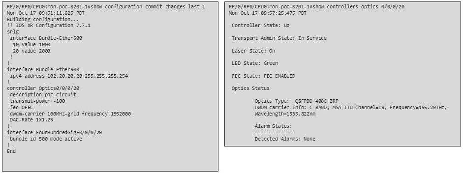
The output for a sample configuration includes these components:
This topology uses two Cisco 8201 routers, two NCS 2006 terminal nodes equipped with NCS1K-MD-64 add/drop multiplexers, and EDFA-35 bidirectional amplifiers. The span length is 75 km. Additional ILA nodes may be required for amplification if the spans are longer.
Automation software resource planning
Identify the servers required for the full solution. See Sample end-to-end configuration and Installation requirements for Routed Optical Networking components.
For a lab or EFT setup, it is recommended to use three servers each with 384 GB of RAM, 32 cores, and two TB SSDs.
The solution requires the use of VMware ESX 6.7 or higher.
The installation requirements for different Routed Optical Networking components are:
The implement phase involves:
Installation of hardware components
Hardware staging or installation and initial base configuration required for management connectivity.
All onboard software updates must be completed to the required revision.
All associated base wiring must be completed to support the network. This includes connections between the optical elements and connections between routers and optical add/drop end-points to support Routed Optical Networking circuits using ZR and ZR+ optics. See Deployment Topologies.
Install Cisco Optical Site Manager to support NCS 1010 nodes. See Install Cisco Optical Site Manager
Installation of automation software somponents
Complete all server hardware installation and base configuration to support the solution, including VMWare ESX if not already installed.
Install the following software components to support the Routed Optical Networking solution.
Cisco Optical Network Planner 5.2 (for optical planning)
Cisco WAN Automation Engine 7.6.x (for IP planning)
Cisco Crosswork Cluster, Crosswork Data Gateway, and Crosswork Applications (for supporting Crosswork Network Controller)
Cisco Optical Network Controller 3.1 (for supporting optical network)
Cisco Evolved Programmable Network Manager 7.1.4 (for managing the physical router and the optical network nodes)
Cisco Network Services Orchestrator 6.1.9 (base installation to support RON FP)
Cisco NSO Routed Optical Networking Core Function Pack 3.0 (for RON ML provisioning)
Cisco NSO Transport-SDN Function Pack Bundle 6.0 (for Crosswork Network Controller SR and xVPN provisioning)
Cisco Network Services Orchestrator DLM Service Pack 6.0 (for device synchronization between Crosswork Network Controller and NSO)
Cisco Crosswork Hierarchical Controller 8.0 (for provisioning the Routed Optical Networking ML service using the Crosswork Hierarchical Controller)
Note |
This is required only if the Routed Optical Networking ML service is provisioned via the Crosswork Hierarchical Controller GUI. |
Onboarding of devices
Add devices to Cisco Optical Network Controller. See Onboard Devices to Cisco Optical Network Controller.
Add NSO, SR-PCE, and devices to Crosswork Network Controller. See Add SR-PCE providers, NSO providers, and routers to Crosswork Network Controller.
Add routers to NSO using the IOS-XR CLI NED. See Step 3 in Provision an ML service using NSO Routed Optical Networking CFP.
Add and configure the following Crosswork Hierarchical Controller adapters. See Configure adapters for Routed Optical Networking in Crosswork Hierarchical Controller.
Note |
This step is required only if the Routed Optical Networking ML service is provisioned via the Crosswork Hierarchical Controller GUI. |
Add and configure the Crosswork Network Controller adapter.
Create or import sites in Crosswork Hierarchical Controller. See the sections, "Add Sites" and "Export and Import Sites" in the Cisco Crosswork Hierarchical Controller Administration Guide 8.0.
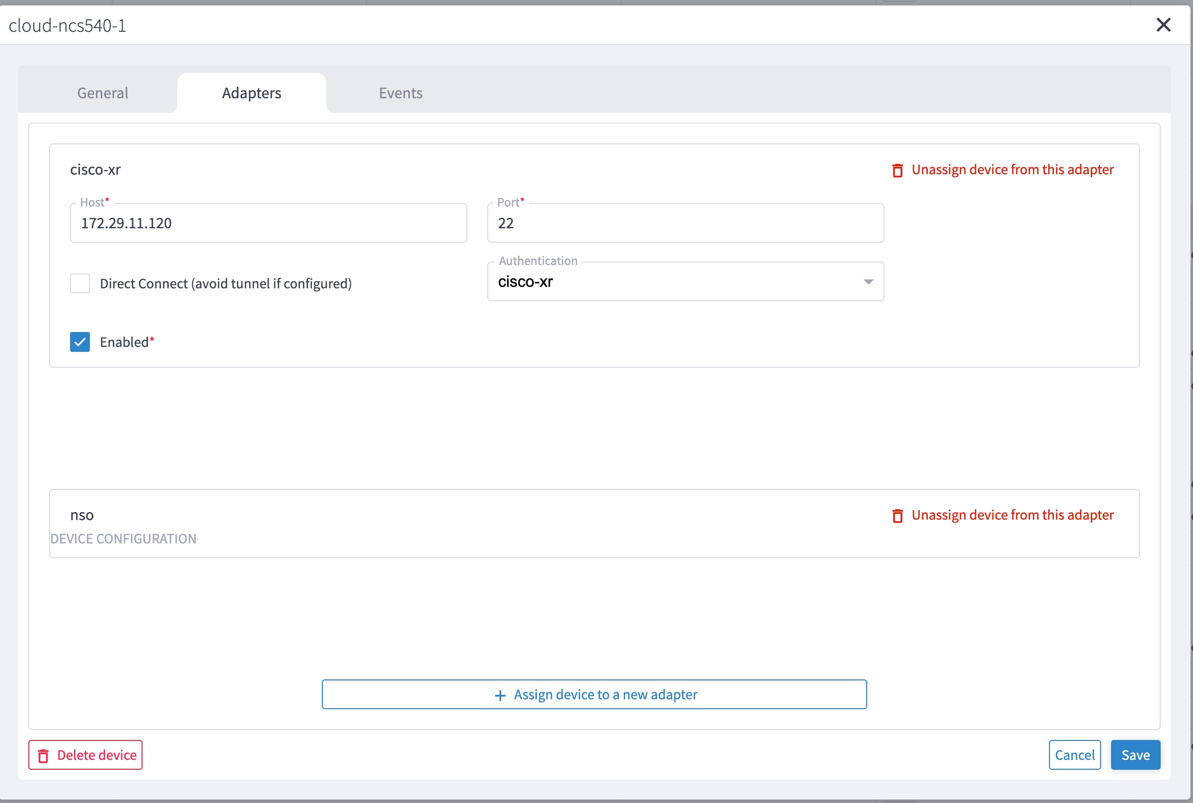
Add and configure the IOS-XR adapter. Create router devices in Crosswork Hierarchical Controller using the IOS-XR adapter type. After the routers are created, add the Crosswork Network Controller adapter to the router device.
Add and configure the Cisco Optical Network Controller adapter.
Provisioning of services
Ensure all device interconnections are complete.
To provision the Routed Optical Networking ML service, use either one of the procedures:
Using the NSO GUI:
Utilize the Routed Optical Networking FP ML services to provision and end-to-end service. See Provision an ML service using NSO Routed Optical Networking CFP.
Verify that the end-to-end service has been deployed by checking the NSO service deployment status using the check-sync status.
Verify the router optics controller state using the CLI or in EPNM. See Troubleshoot provisioning issues on ZR or ZR+ optics.
Using the Crosswork Hierarchical Controller GUI:
Utilize the Crosswork Hierarchical Controller GUI to provision and end-to-end Routed Optical Networking ML service. See Provision a Routed Optical Networking ML service using Crosswork Hierarchical Controller.
Verify the router optics controller state using the Link Assurance tool in Crosswork Hierarchical Controller. See Step 4 in Provision a Routed Optical Networking ML service using Crosswork Hierarchical Controller.
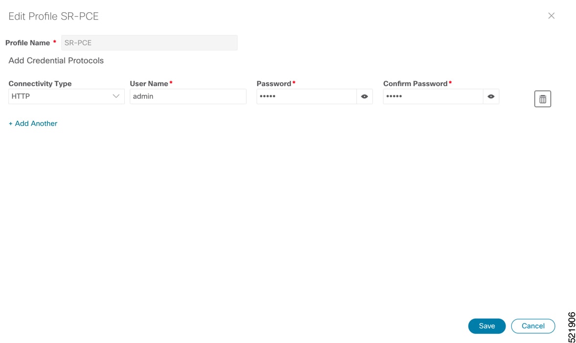
Follow these steps to add SR-PCE providers, NSO providers, and routers to Crosswork Network Controller.
Note |
When you add or import devices, or create providers, you need to specify the credential profile. |
|
Step 1 |
Log in to the Crosswork user interface. |
|
Step 2 |
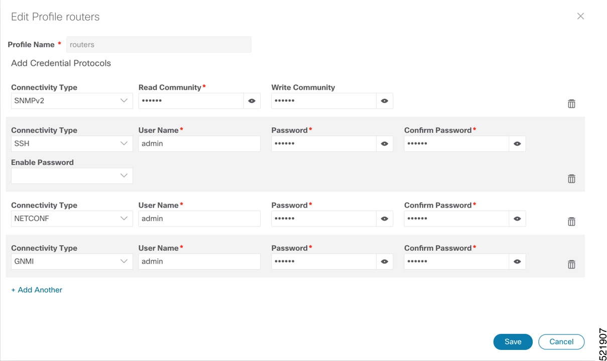
Choose from the main menu to create a credential profile. See Manage Credential Profiles.
|
|
Step 3 |
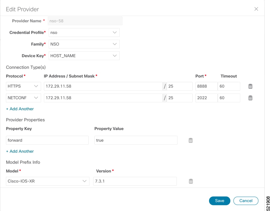
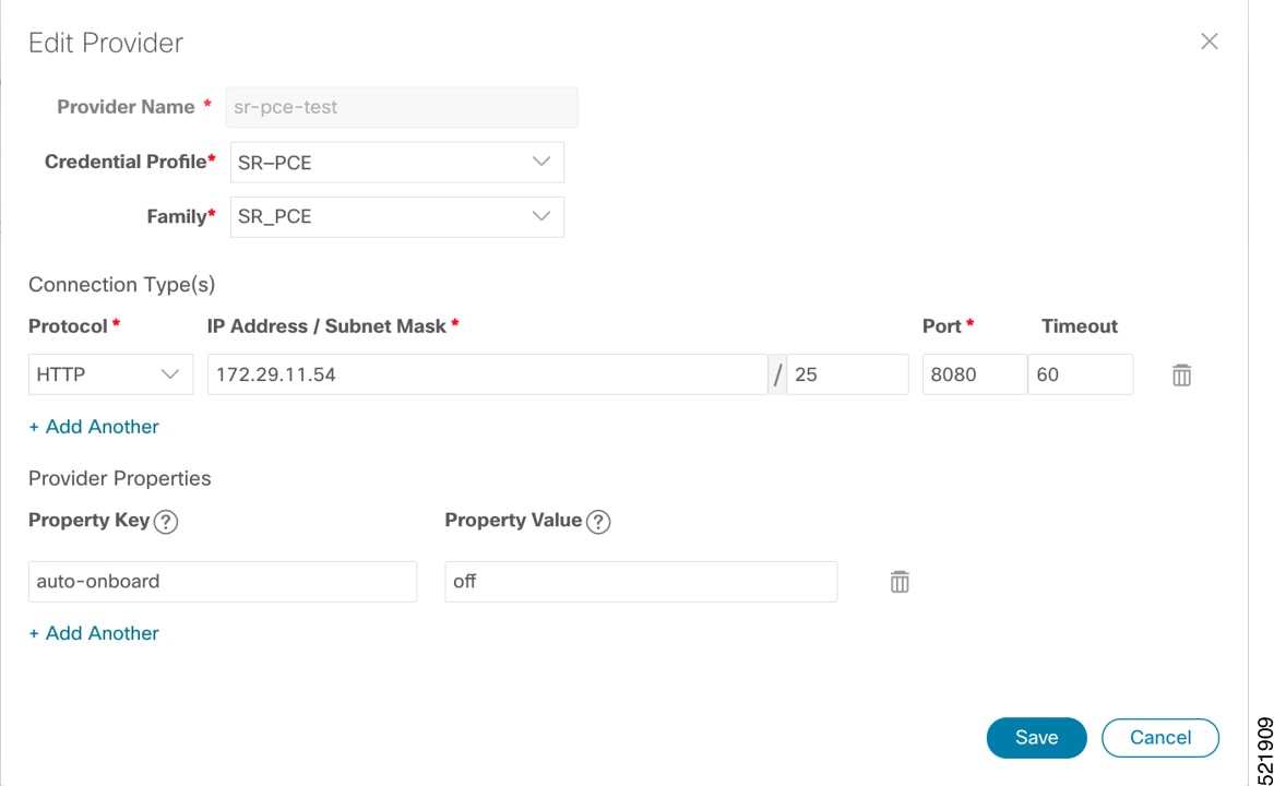
Add the providers. See About Adding Providers.
|
|
Step 4 |
Validate communications with one or more providers. Check the reachability of the provider using Get Provider Details. |
|
Step 5 |
Onboard devices. See Add Devices Through the UI.
|
SR-PCE providers, NSO providers, and routers appear in Crosswork Network Controller and are ready for management and monitoring.
These adapters are needed for the Routed Optical Networking solution.
|
Adapter |
Credential type |
|---|---|
|
Crosswork Network Controller |
HTTP (username and password) |
|
Crosswork Network Controller Crosswork Data Gateway |
HTTP (username and password) |
|
Cisco Optical Network Controller |
HTTP (username and password) |
|
IOS-XR |
SSH (username and password) |
Note |
If Cisco Optical Network Controller and Crosswork Network Controller are on the same Crosswork cluster, use the same credential profile for both. |
To use Crosswork Hierarchical Controller adapters, you are required to use credentials. These credentials are used for authentication when a device is assigned to an adapter. You can use the same credentials for multiple adapters.
The credentials are added under the tab in the Crosswork Hierarchical Controller GUI.
Follow these steps to add the adapters:
|
Step 1 |
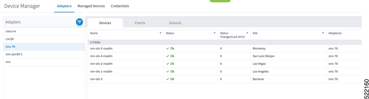
Choose in the applications bar in Crosswork Hierarchical Controller. |
||||||||||
|
Step 2 |
Click Add new adapter to add a new adapter. |
||||||||||
|
Step 3 |
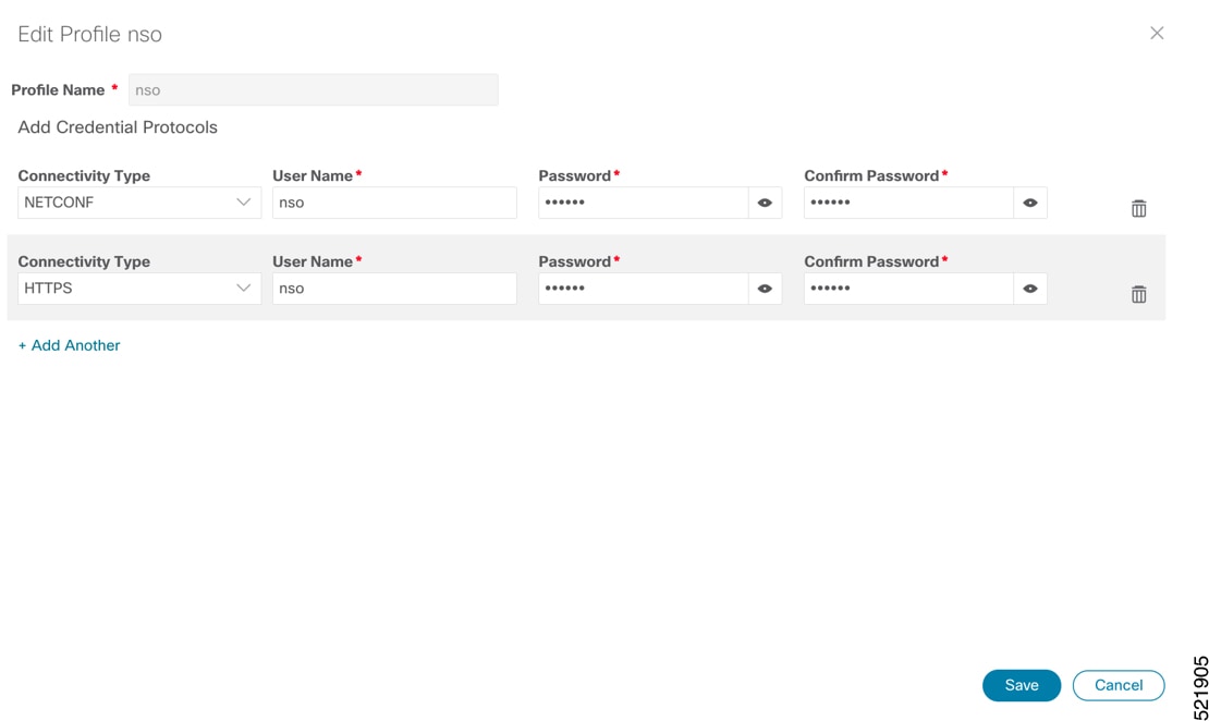
Enter the adapter details:
|
||||||||||
|
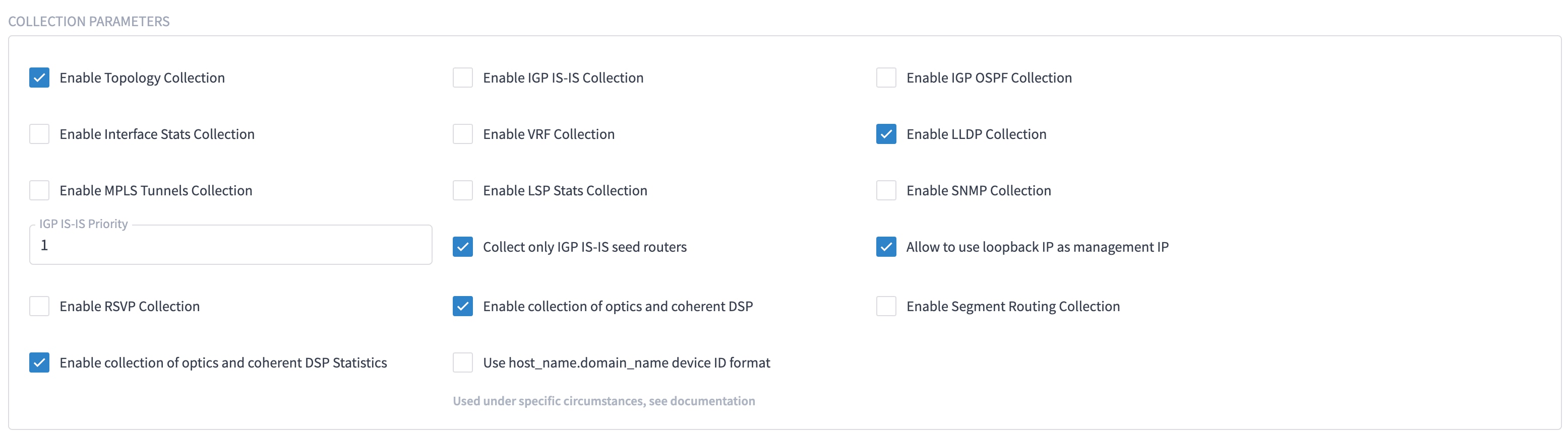
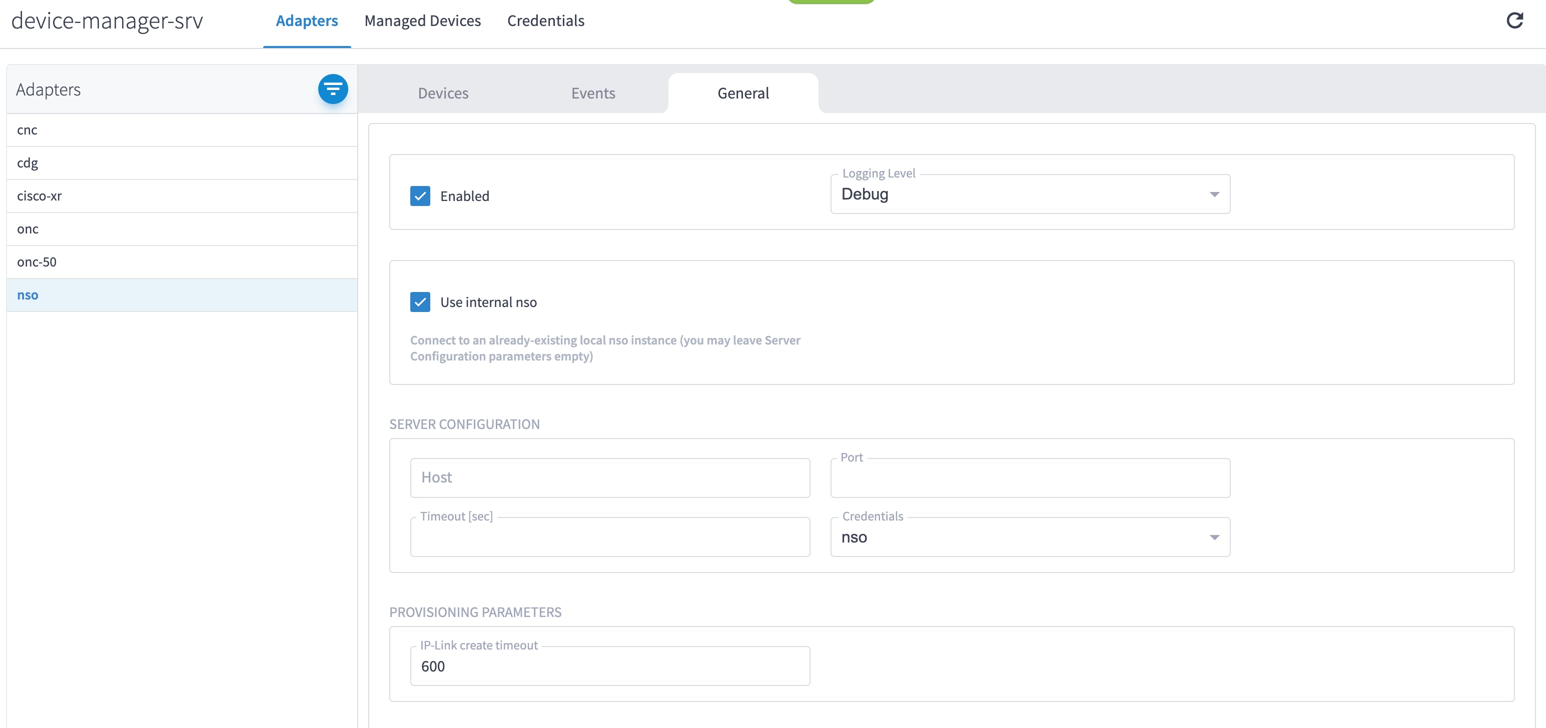
Step 4 |
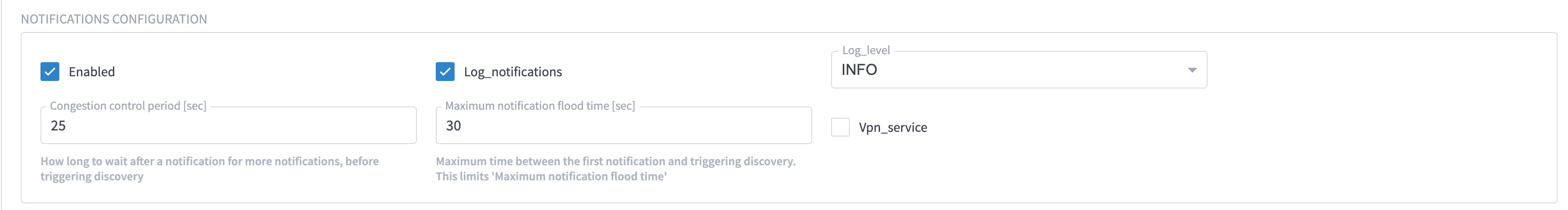
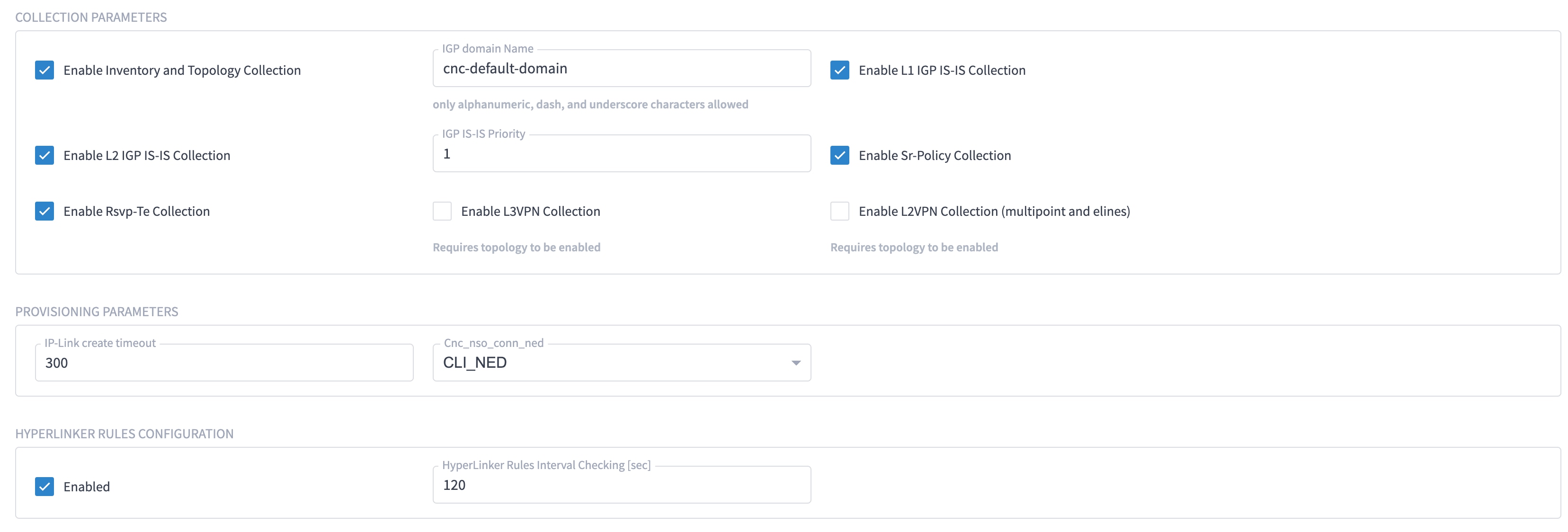
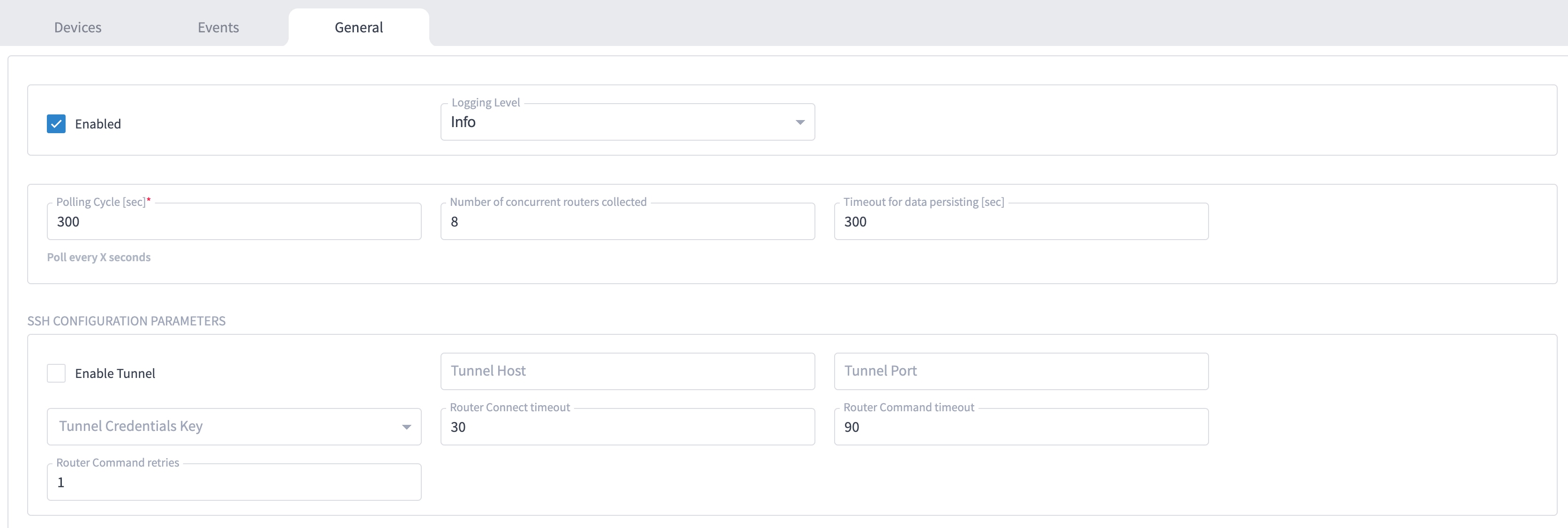
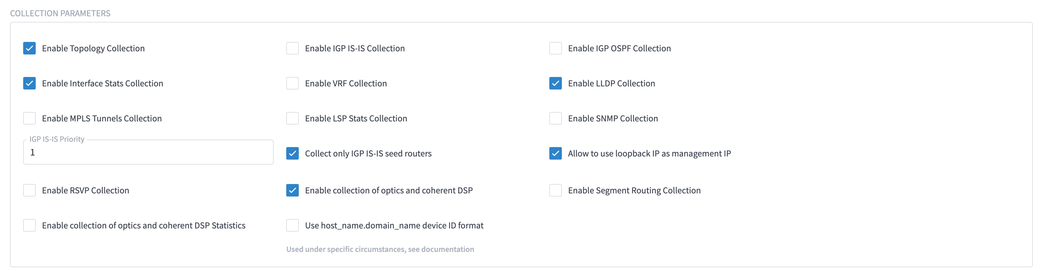
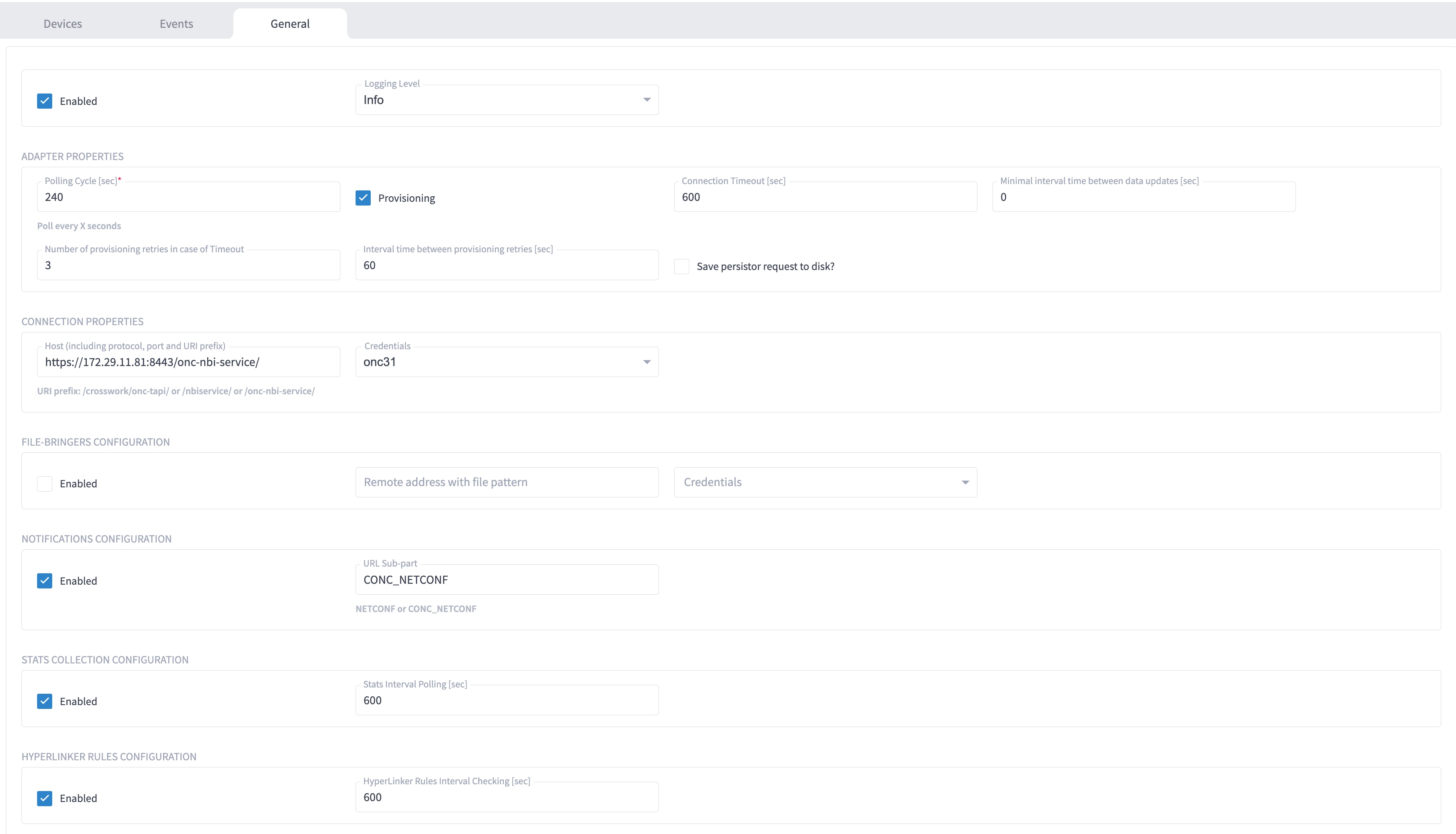
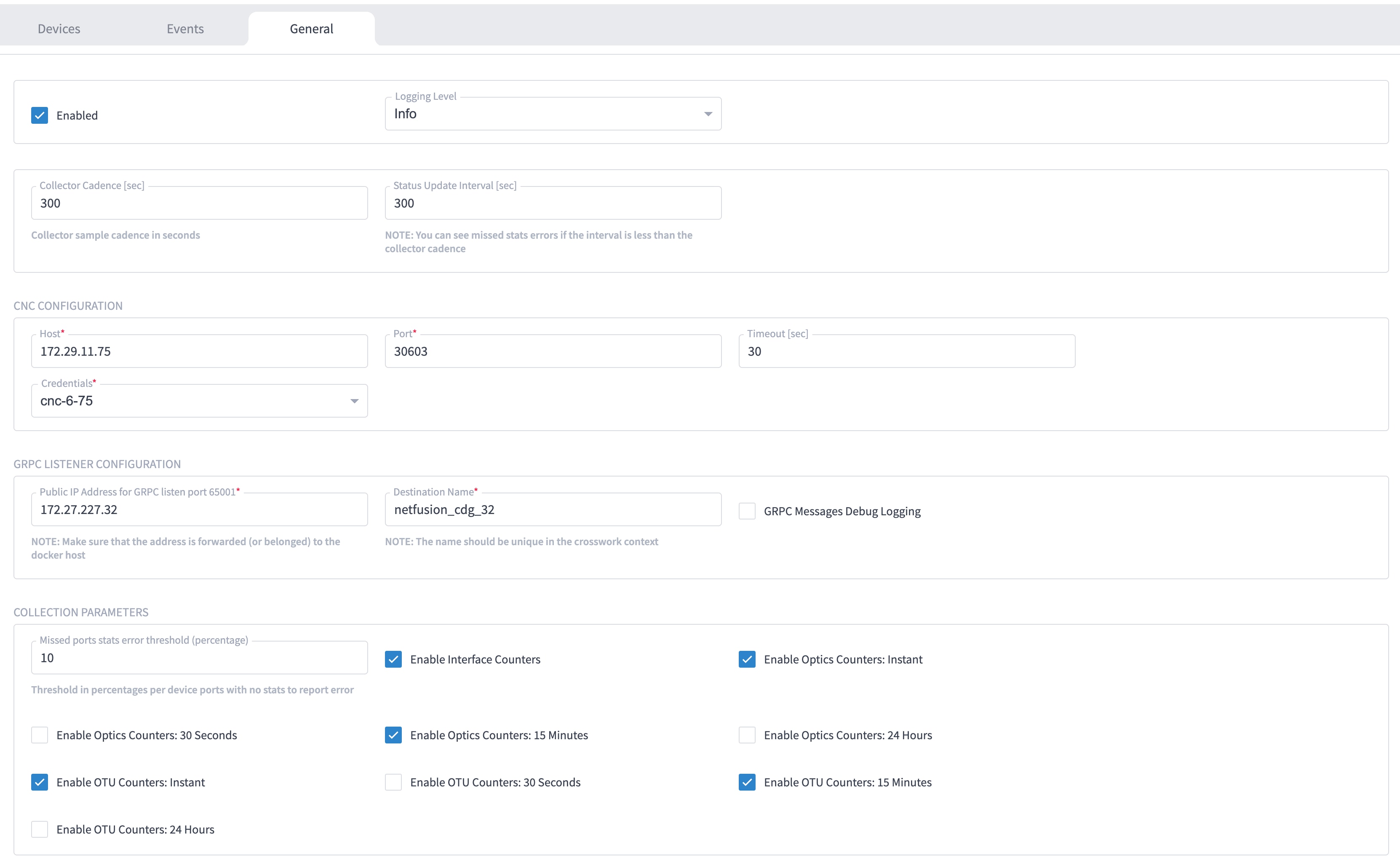
Select the adapter in the Adapters pane to configure the adapter. Configure the parameters as shown in these images.
|
The selected adapters are configured and ready for device assignment.
Enable Single Sign-On (SSO) in Crosswork Hierarchical Controller using Crosswork Network Controller as the identity provider.
Use this task when you need to configure SSO in Crosswork Hierarchical Controller with Crosswork Network Controller as Identity Provider. You can use the same SSO configuration to set up SSO for Cisco Optical Network Controller Release 3.1.
|
Step 1 |
Configure Crosswork Hierarchical Controller.
|
|
Step 2 |
Copy the SAML metadata from Crosswork Hierarchical Controller to a file. The metadata is at https://<HCO_IP_address>:<port>/sso/metadata. This file is a sample. |
|
Step 3 |
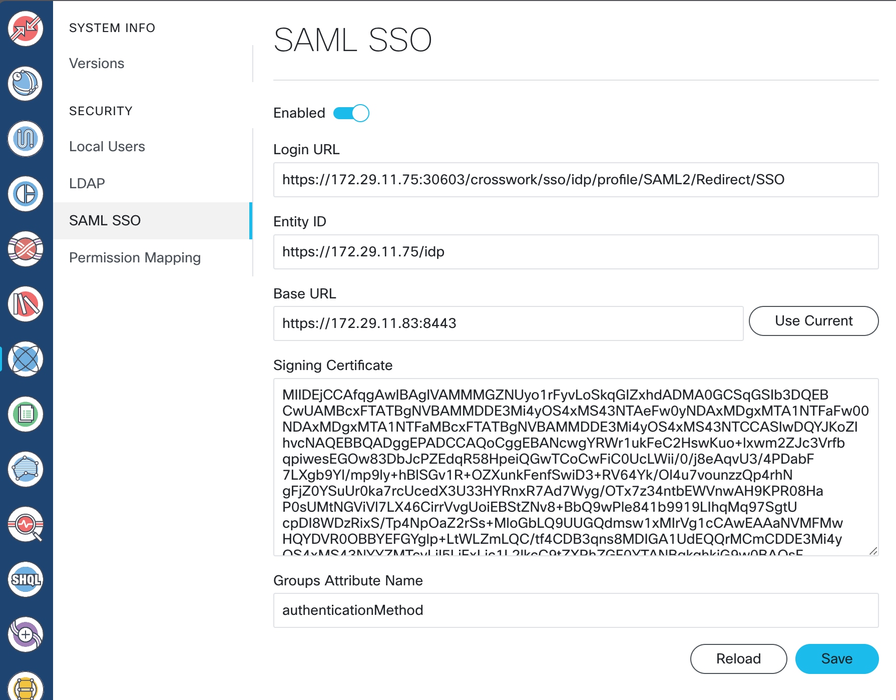
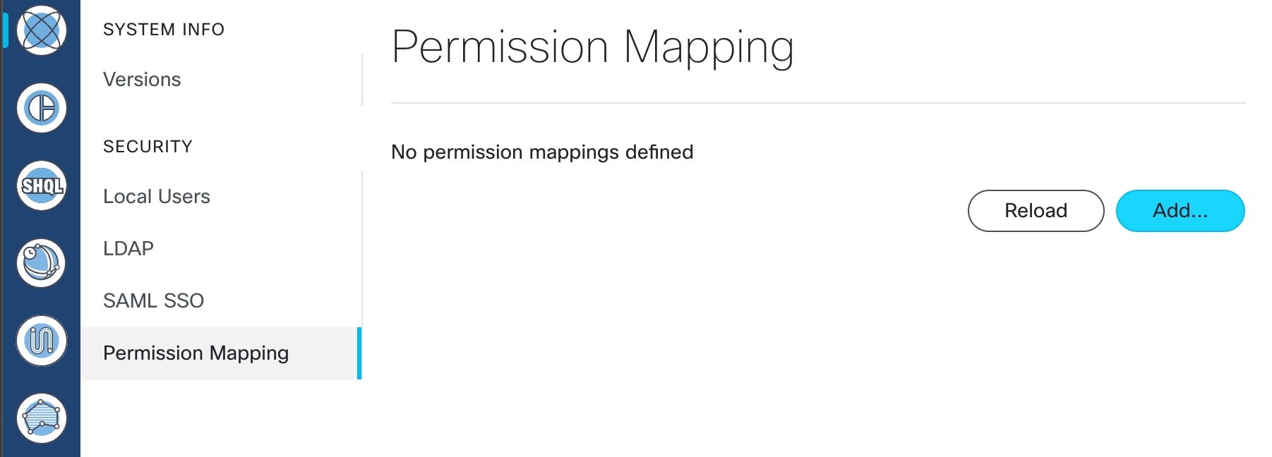
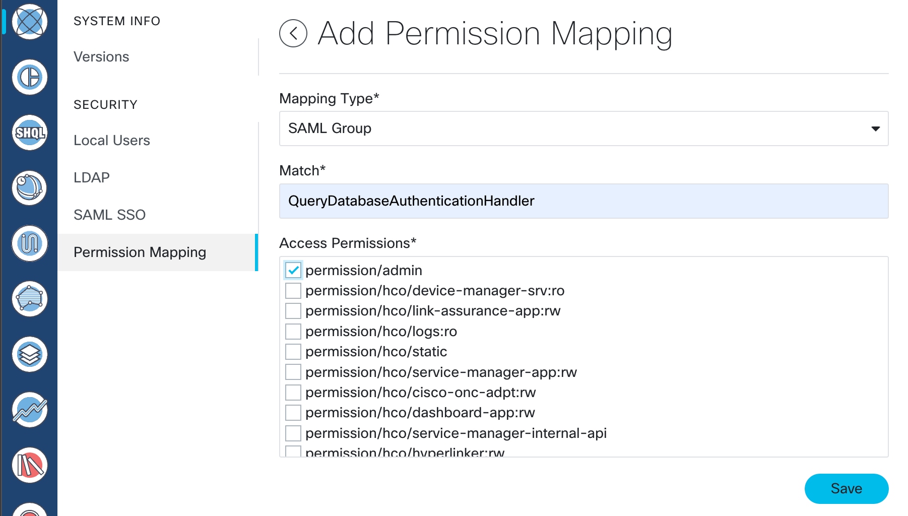
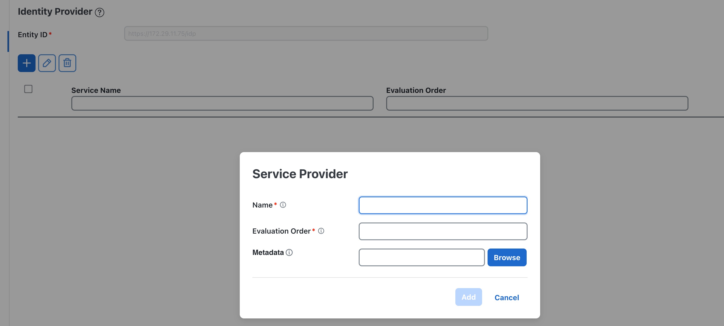
Configure Crosswork Network Controller.
|
|
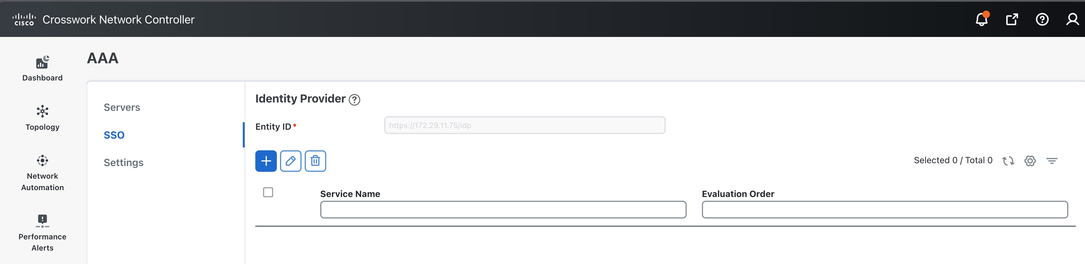
Step 4 |
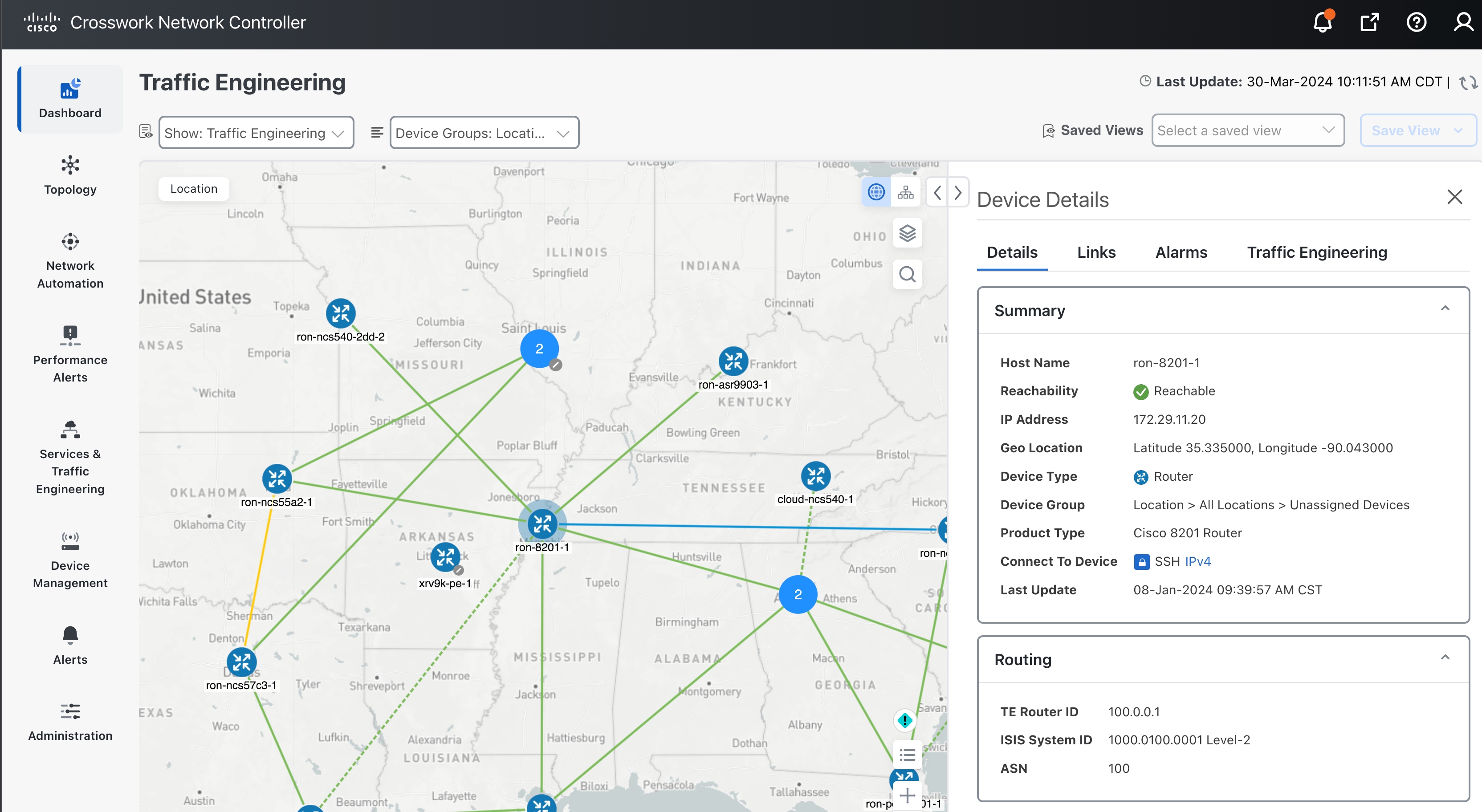
Log in to Crosswork Network Controller. 
Troubleshooting Cisco Crosswork Hierarchical Controller SSO
|
SSO is supported across Crosswork Hierarchical Controller 8.0, Crosswork Network Controller 6.0, Cisco Optical Network Controller, and Cisco Optical Site Manager.
|
Step 1 |
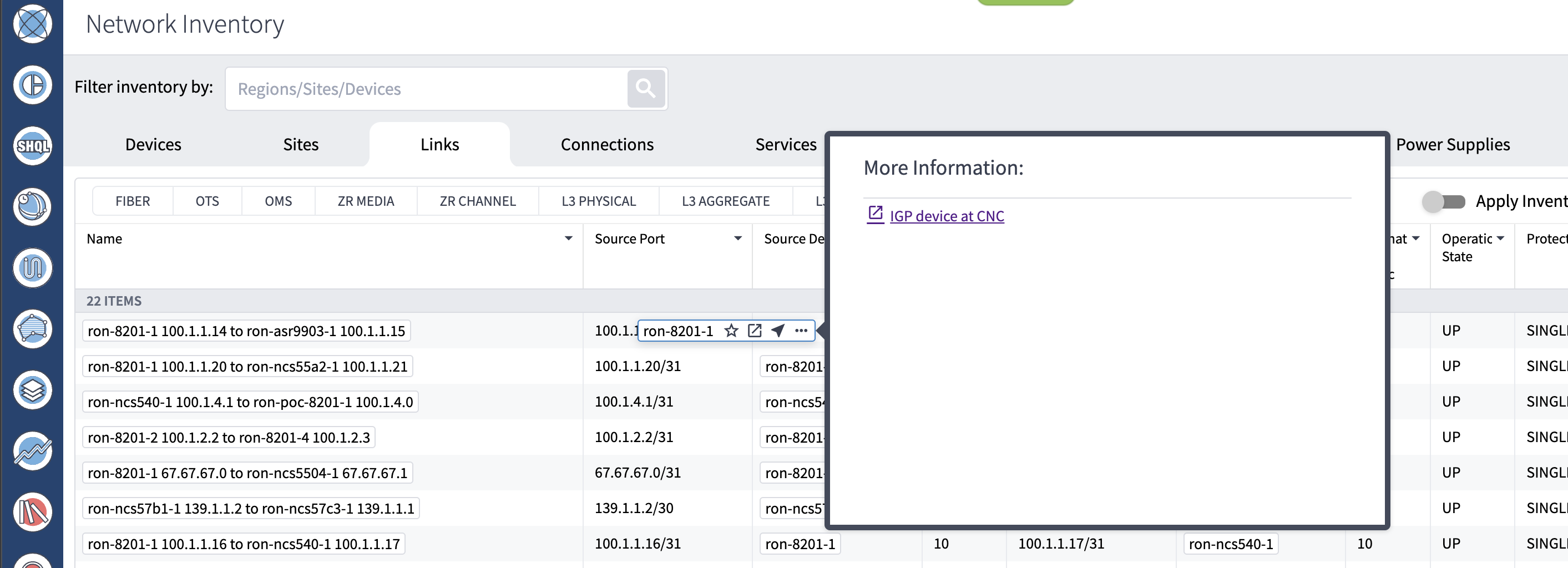
Cross launch from the IGP link source or destination router in Crosswork Hierarchical Controller to Crosswork Network Controller.
|
|
Step 2 |
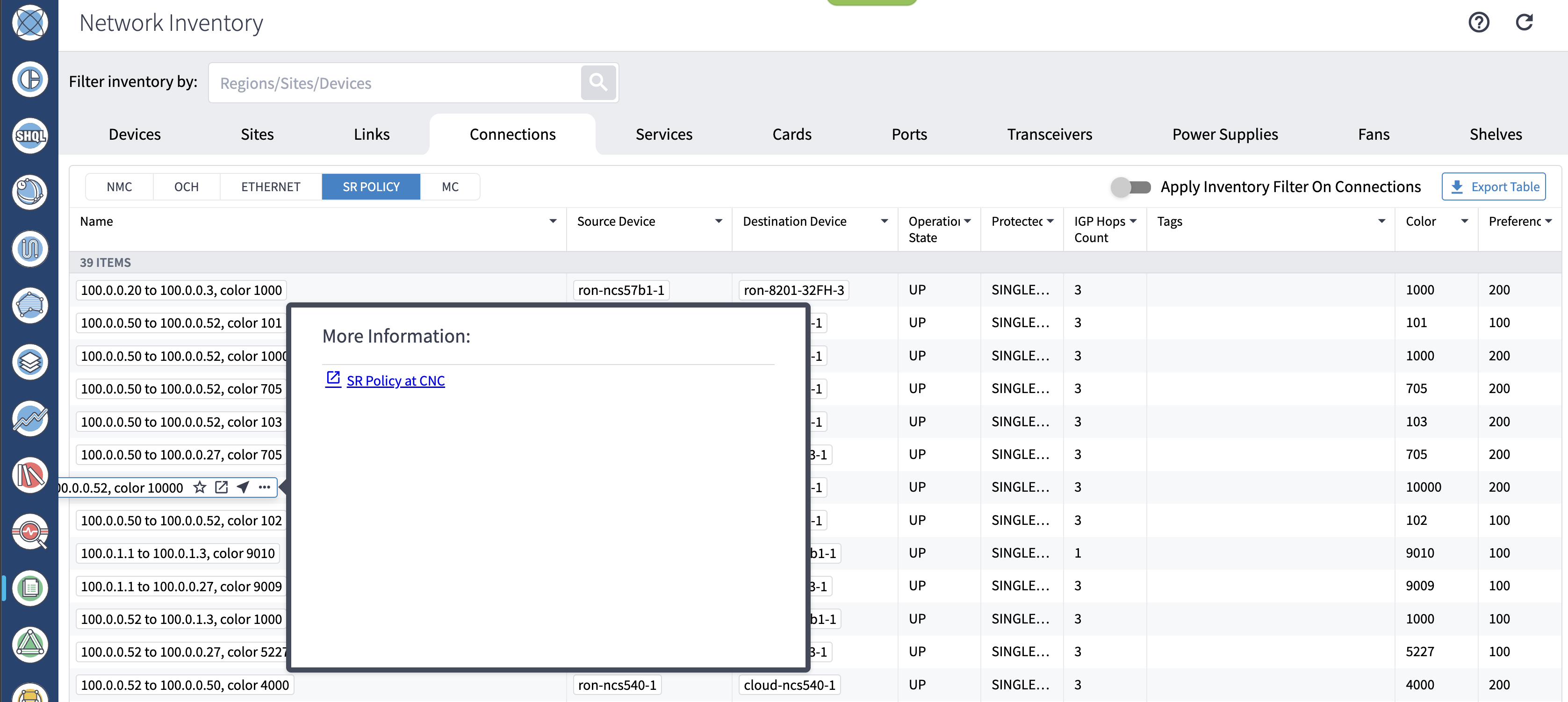
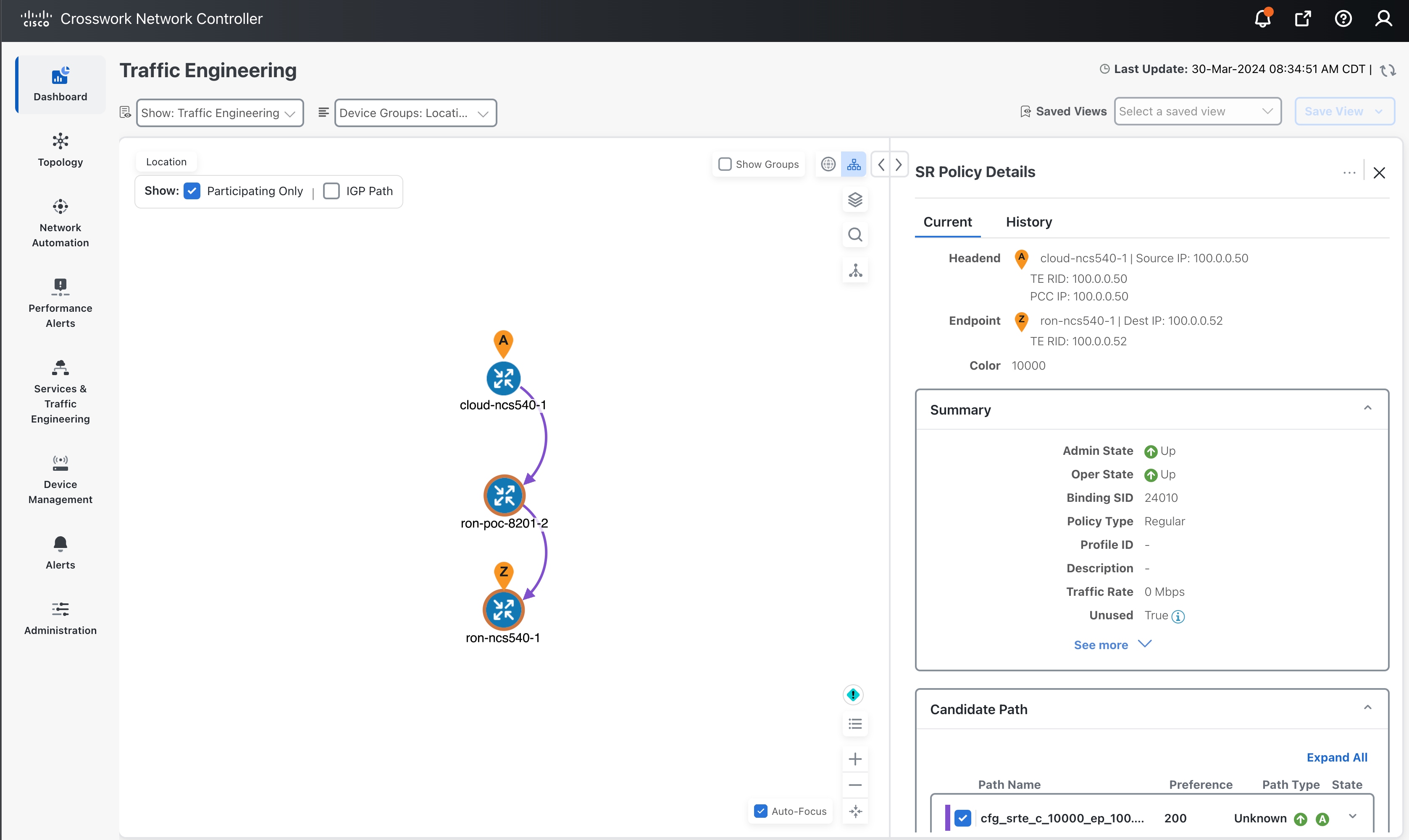
Cross launch from Crosswork Hierarchical Controller SR Policy to Crosswork Network Controller.
|
|
Step 3 |
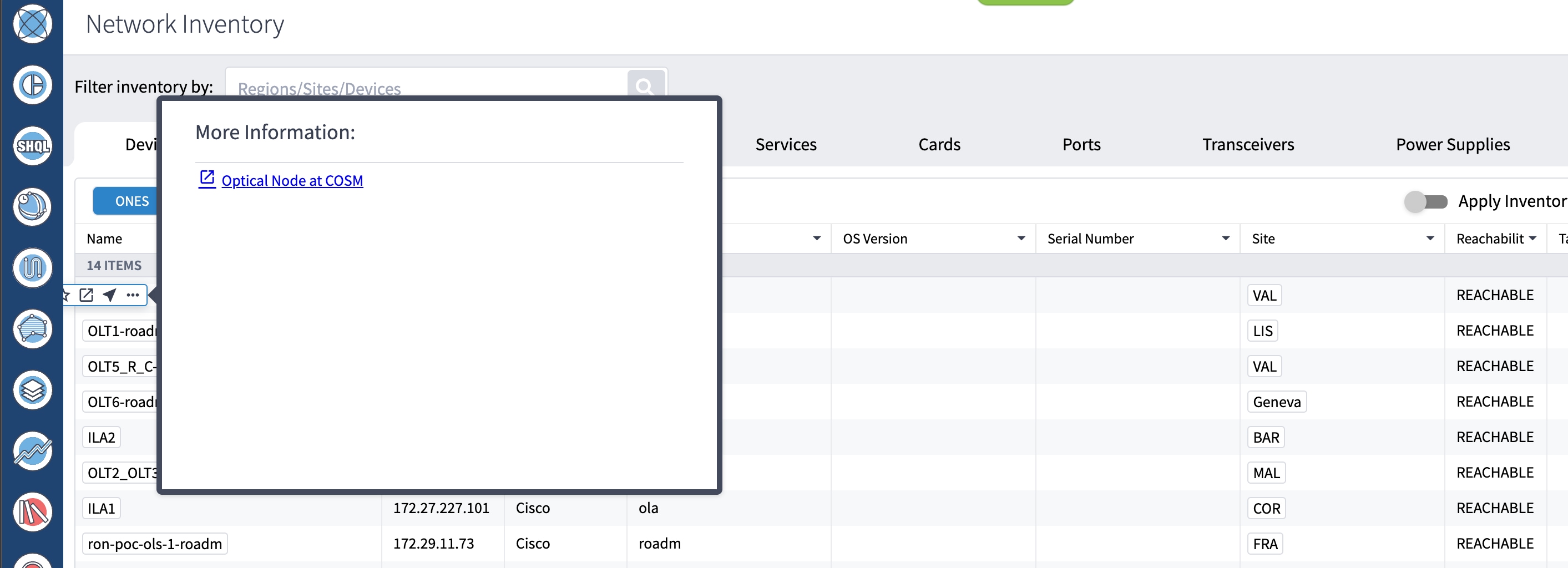
Cross launch from Crosswork Hierarchical Controller optical node to Cisco Optical Site Manager.
|
|
Step 4 |
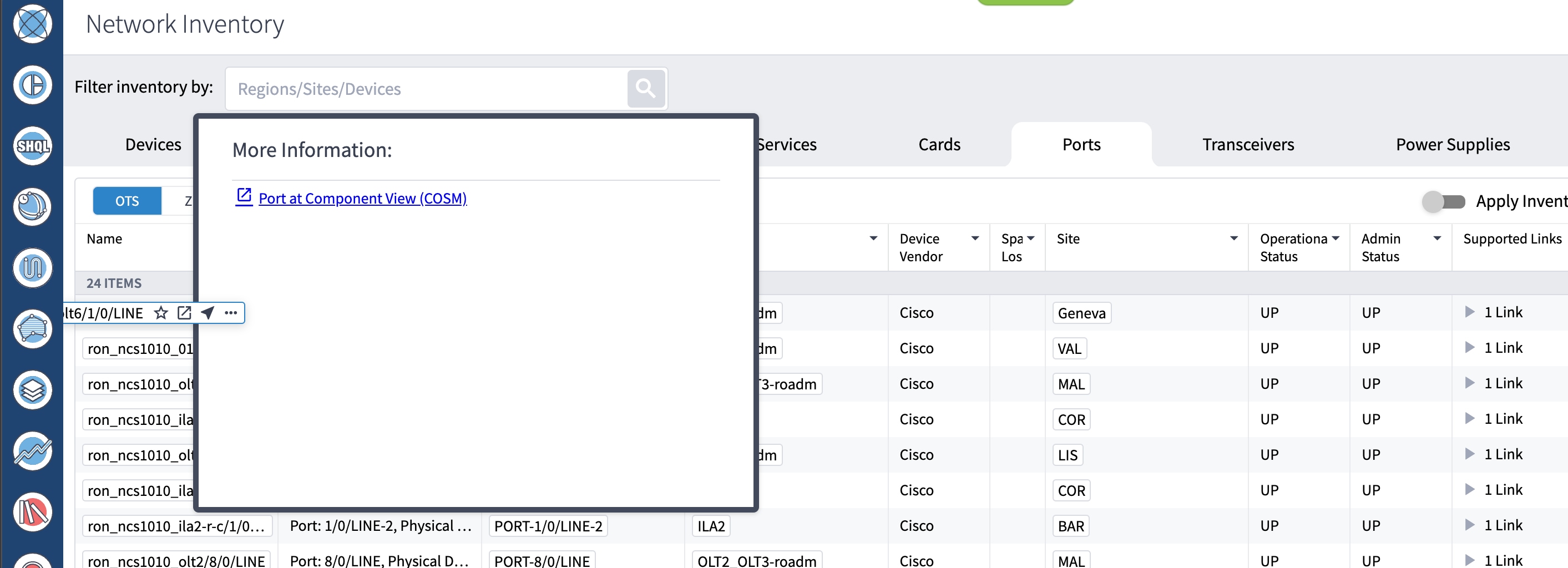
Cross launch from Crosswork Hierarchical Controller optical port to Cisco Optical Site Manager.
|
|
Step 5 |
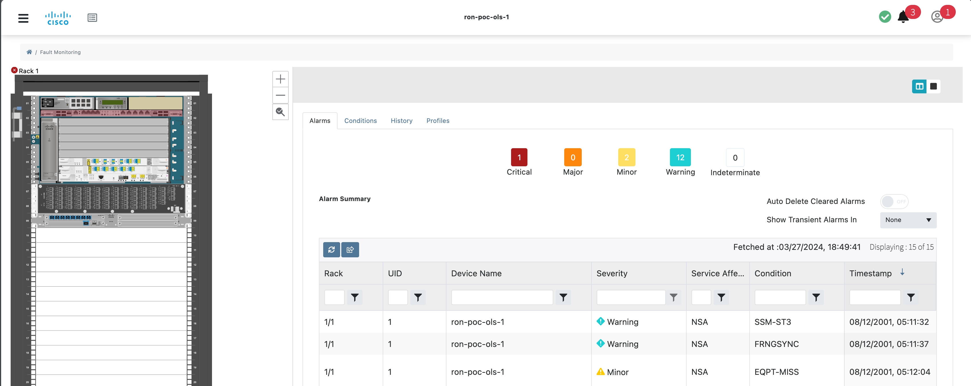
Cross launch from Crosswork Hierarchical Controller Link Assurance node to Cisco Optical Site Manager or SVO.
|
|
Step 6 |
Cross launch from Crosswork Hierarchical Controller Link Assurance port to Cisco Optical Site Manager.
|
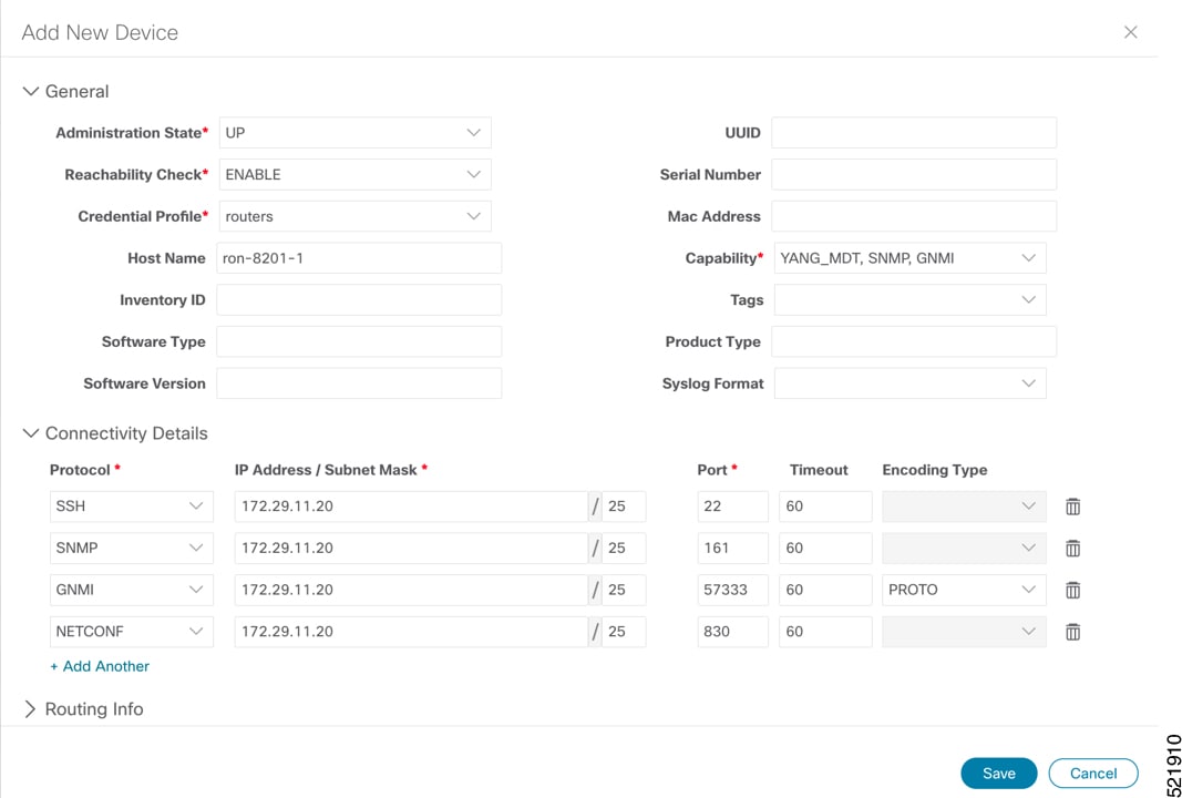
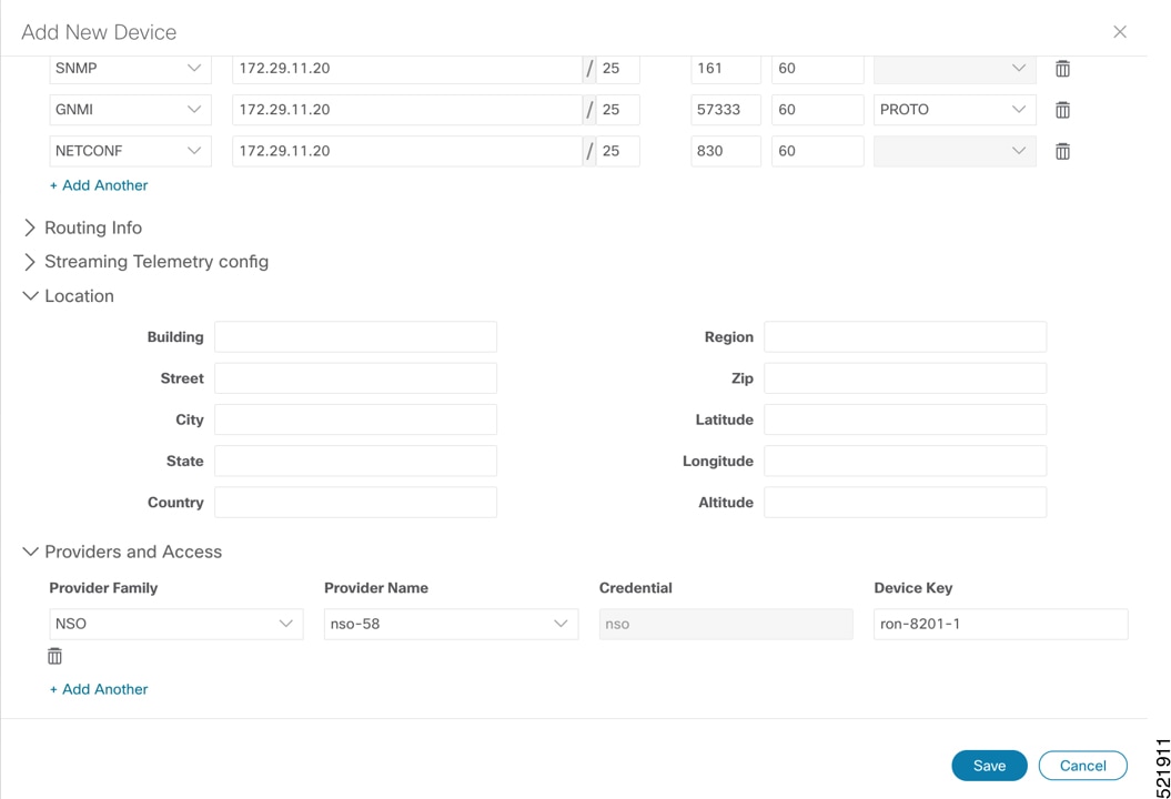
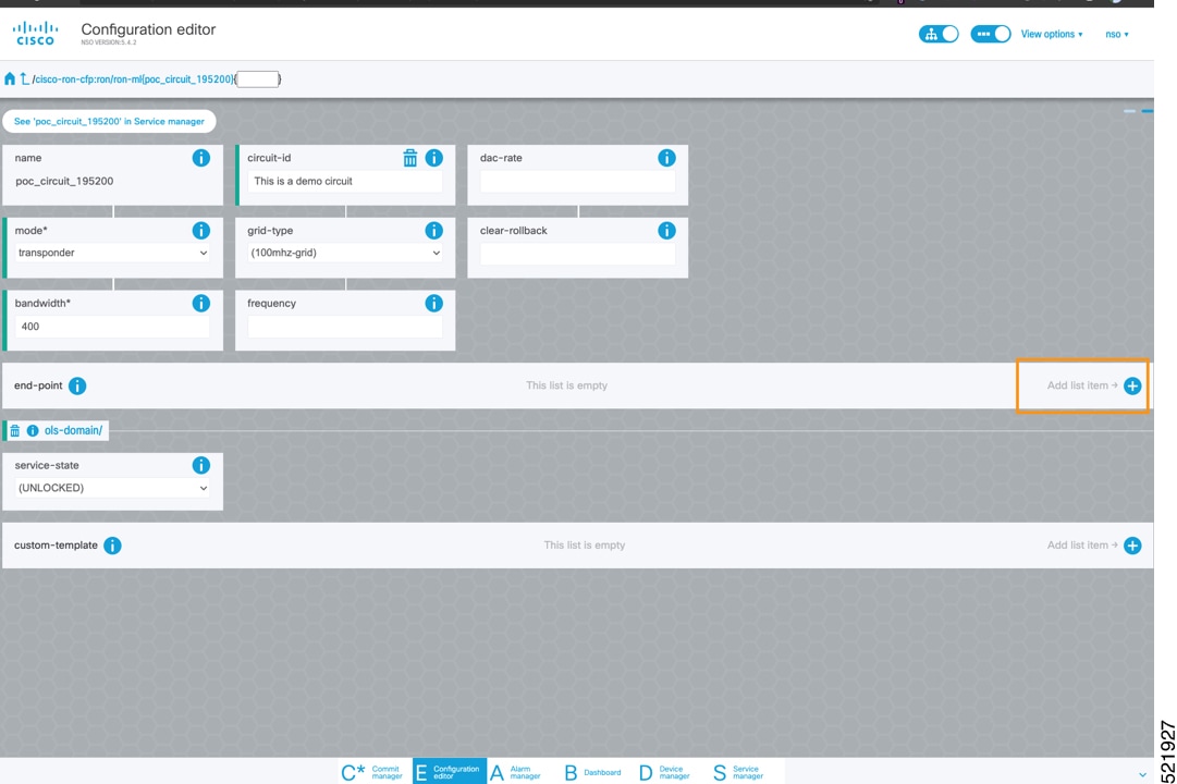
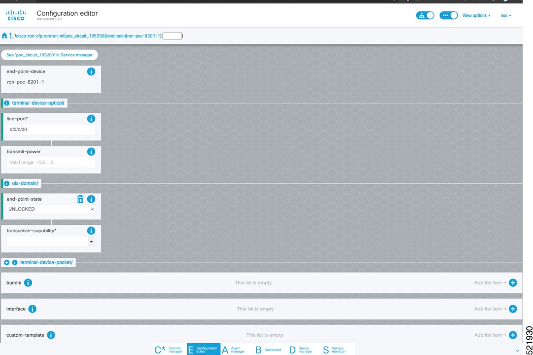
Follow these steps to provision the Routed Optical Networking ML service using the NSO Web UI.
|
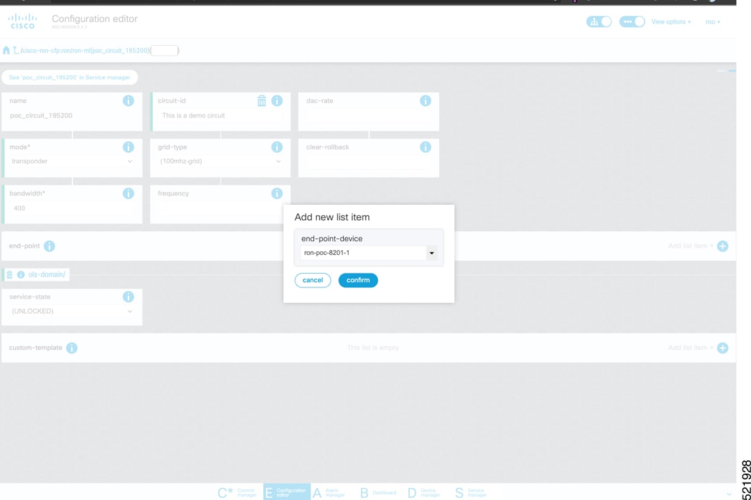
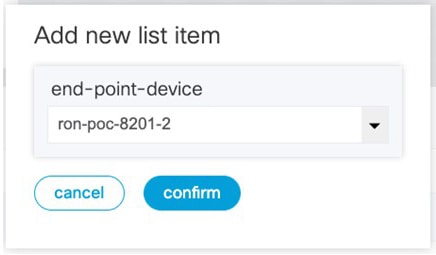
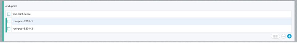
Step 1 |
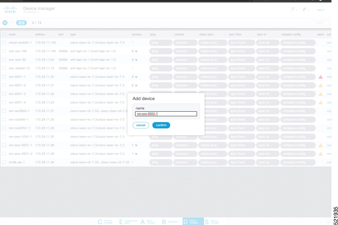
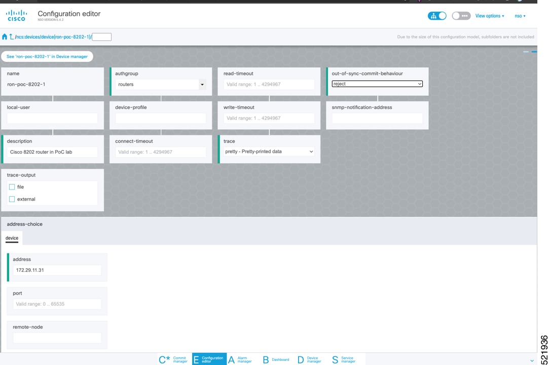
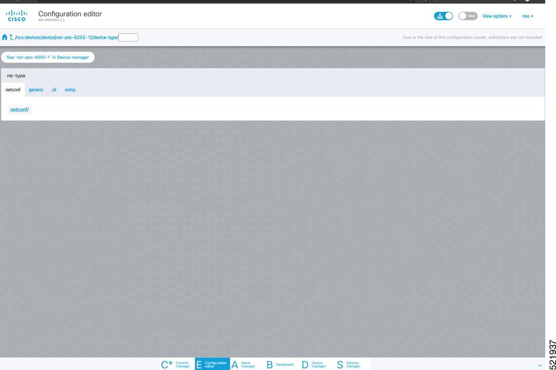
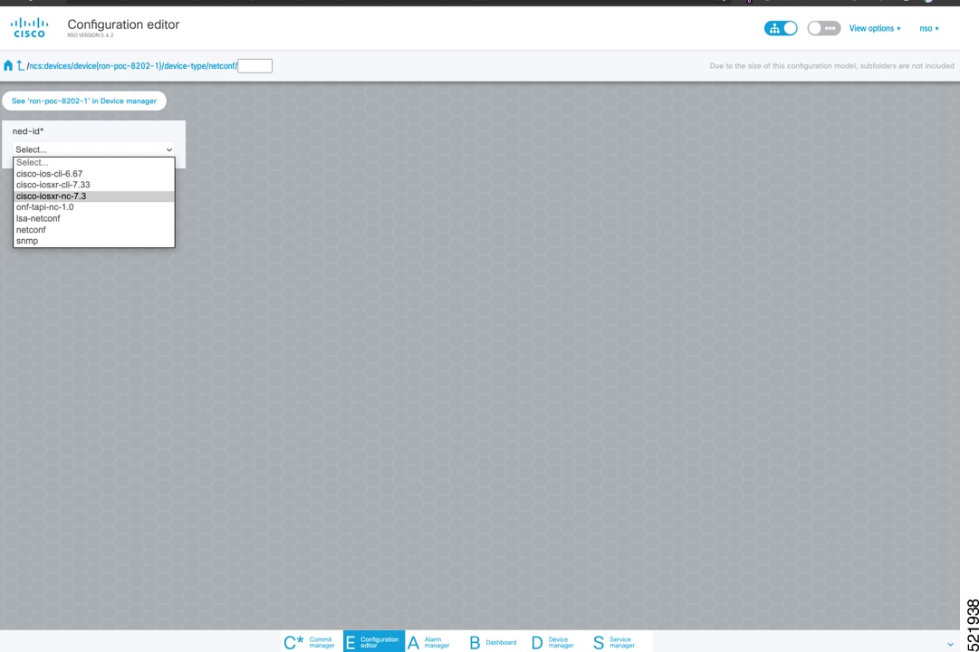
To add a new device, perform these steps:
|
||||||||
|
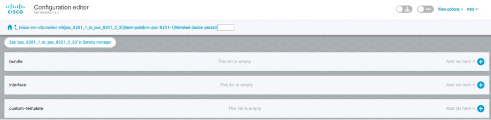
Step 2 |
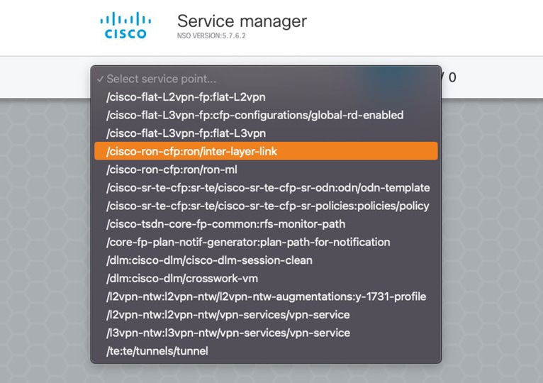
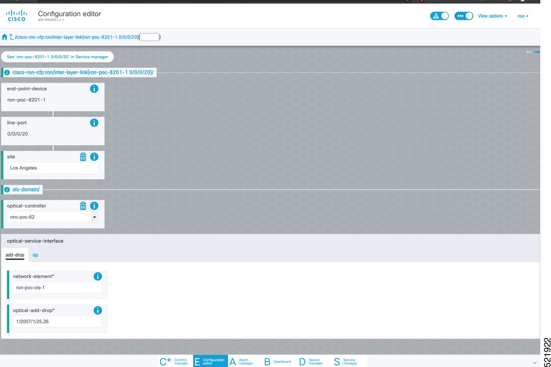
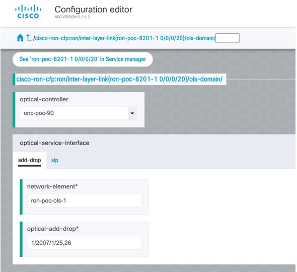
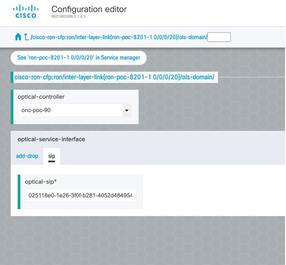
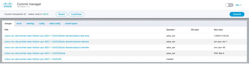
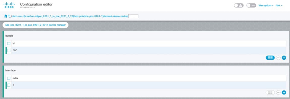
To configure the interlayer link service in NSO, perform these steps:
|
||||||||
|
Step 3 |
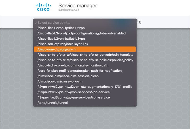
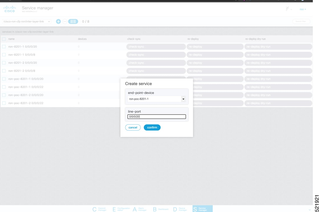
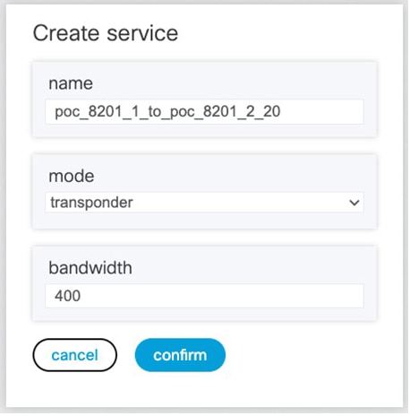
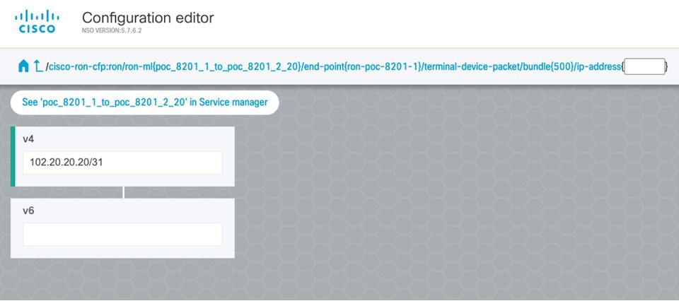
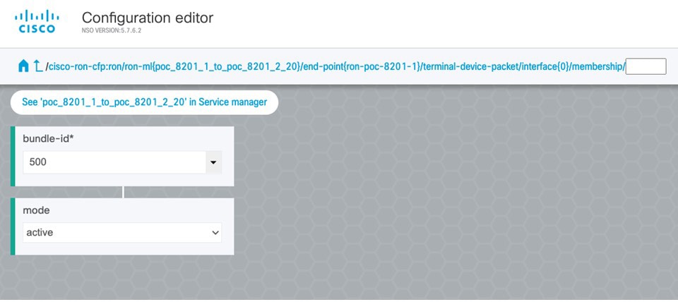
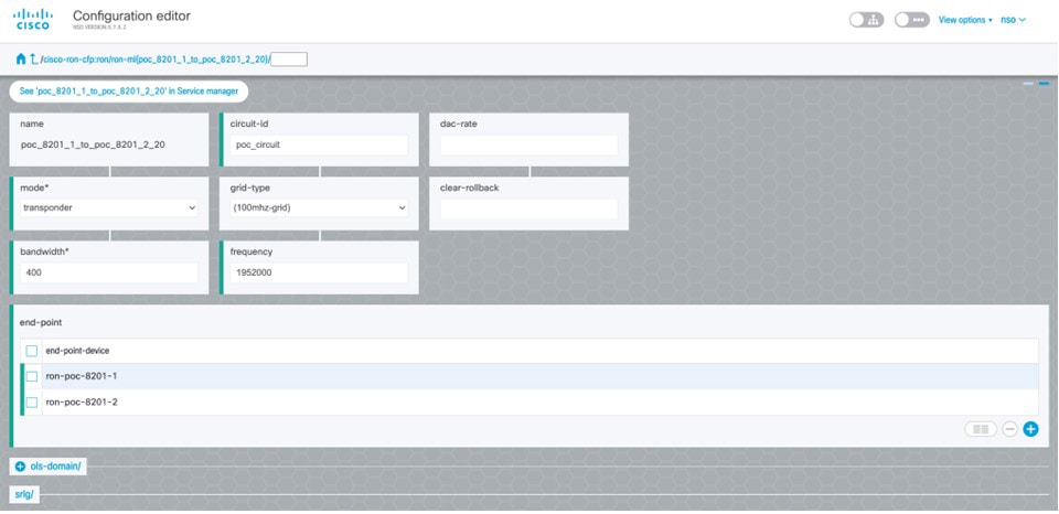
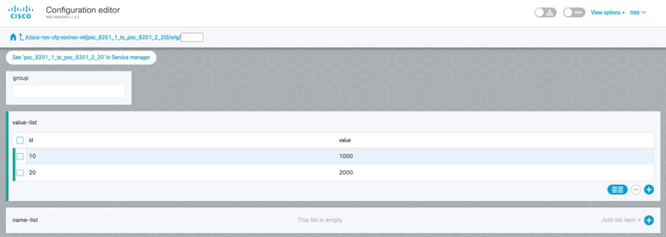
To create Routed Optical Networking ML service, perform these steps:
|
||||||||
|
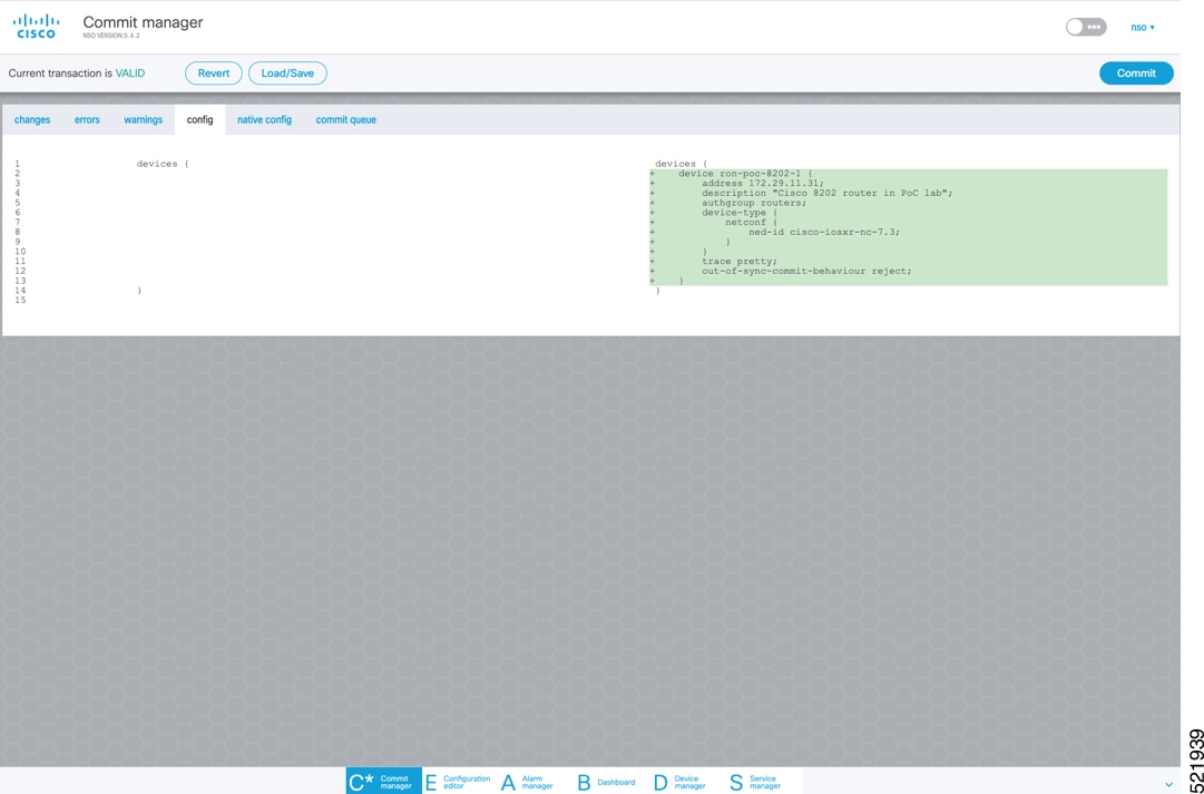
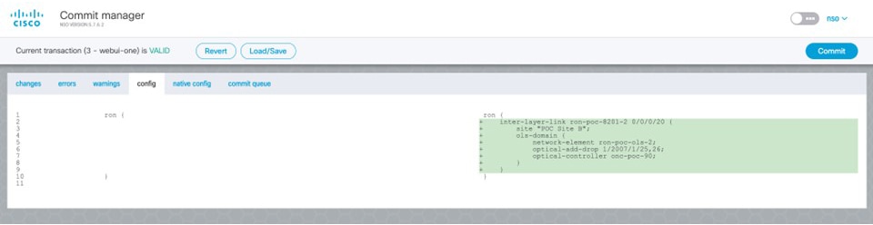
Step 4 |
In the Commit manager, click the config tab. The NSO CLI configuration for the end-to-end service is displayed. If the ols-domain component is not specified in the global configuration, no optical line system provisioning is performed, only router provisioning. You can preview and then commit the configuration. 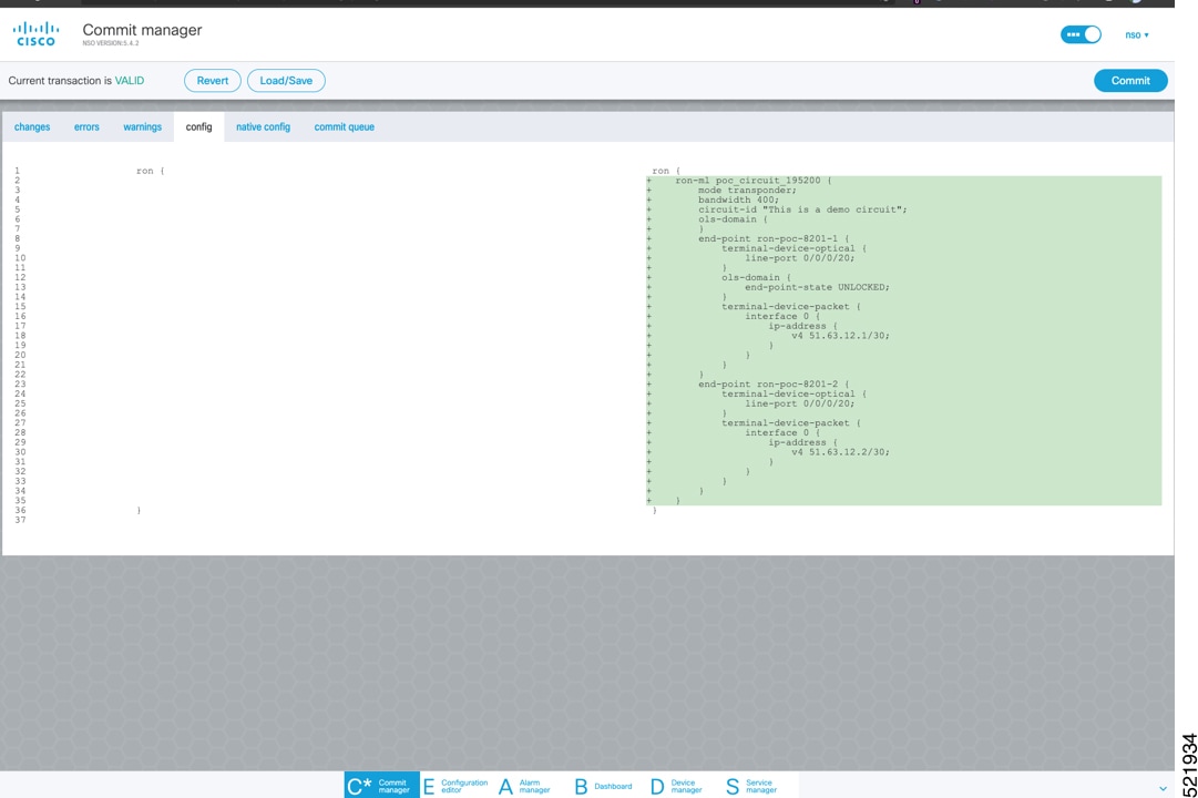 |
||||||||
|
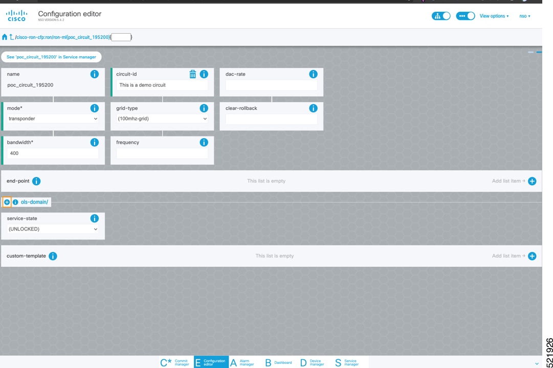
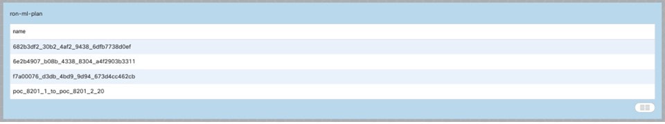
Step 5 |
Verify status in NSO UI. You can verify the status by inspecting the plan associated with the service. You can find the plan under the main ron-ml configuration which you can access by clicking the top portion of the service configuration. An example is highlighted in this image. 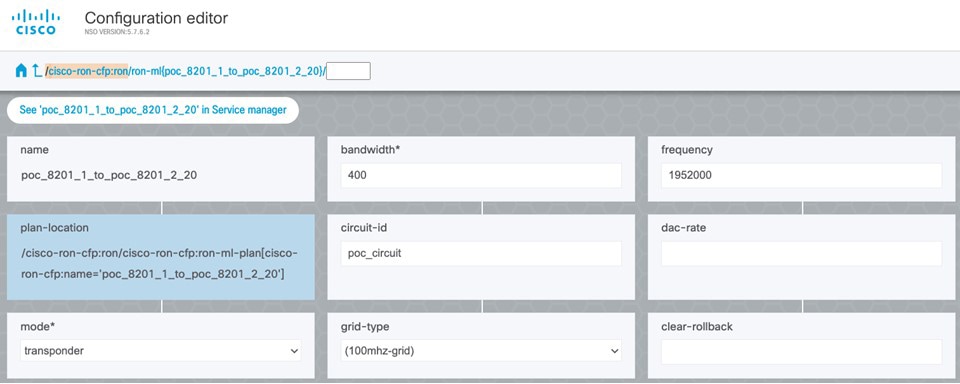
|
Follow these steps to provision Routed Optical Networking ML service using Crosswork Hierarchical Controller.
|
Step 1 |
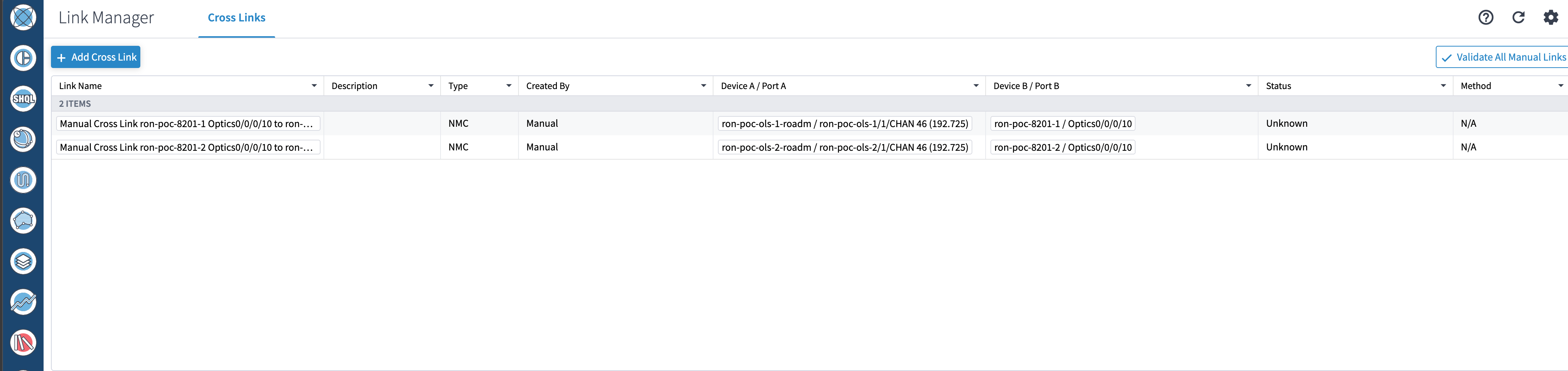
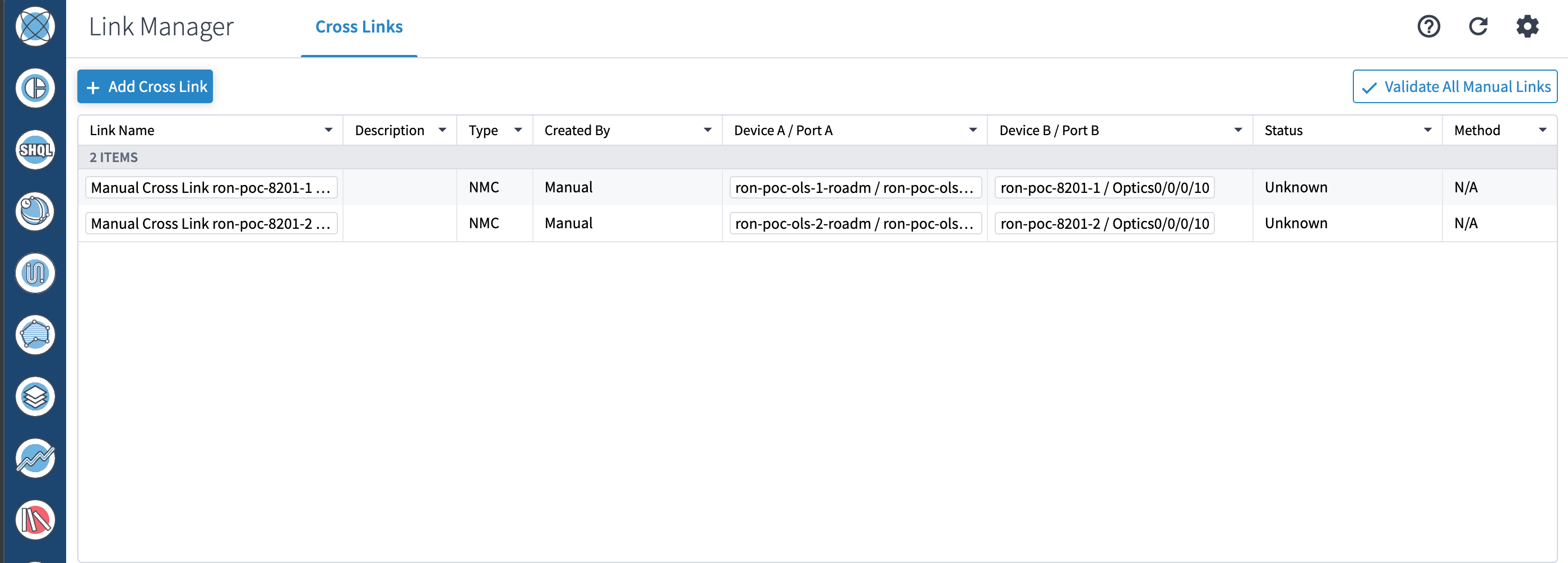
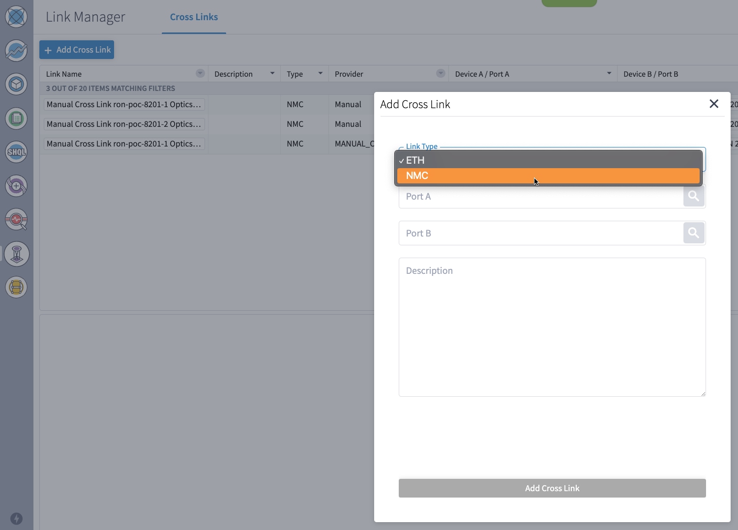
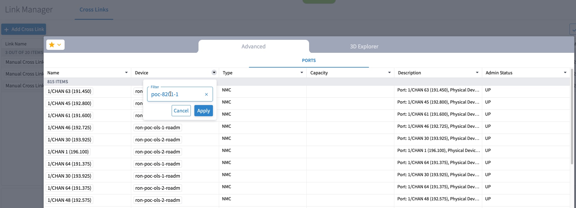
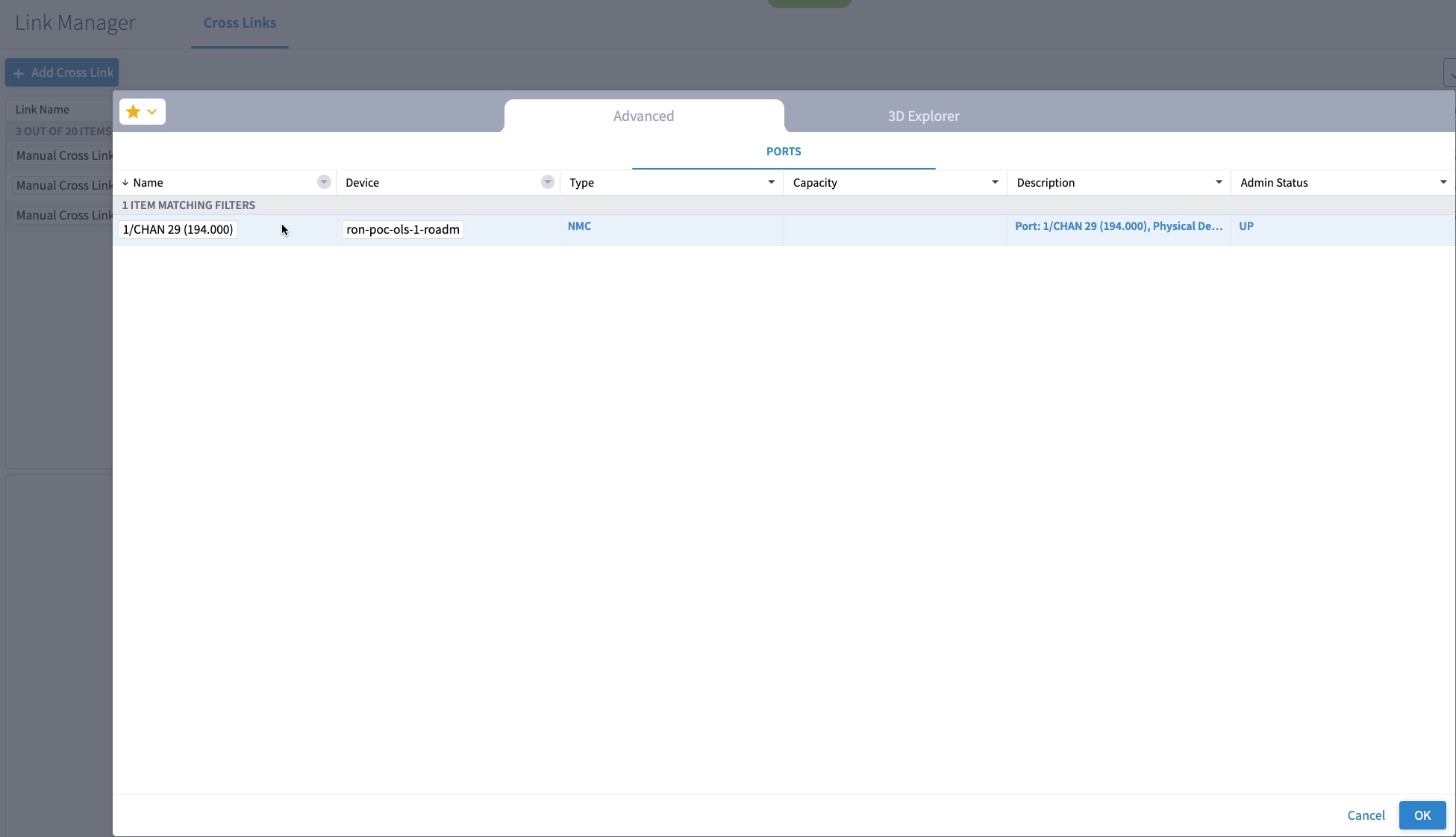
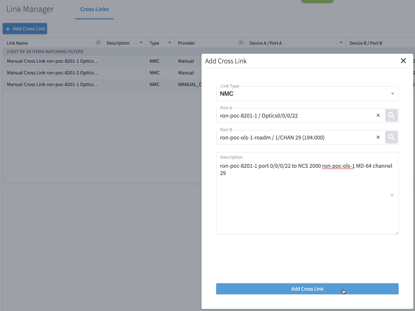
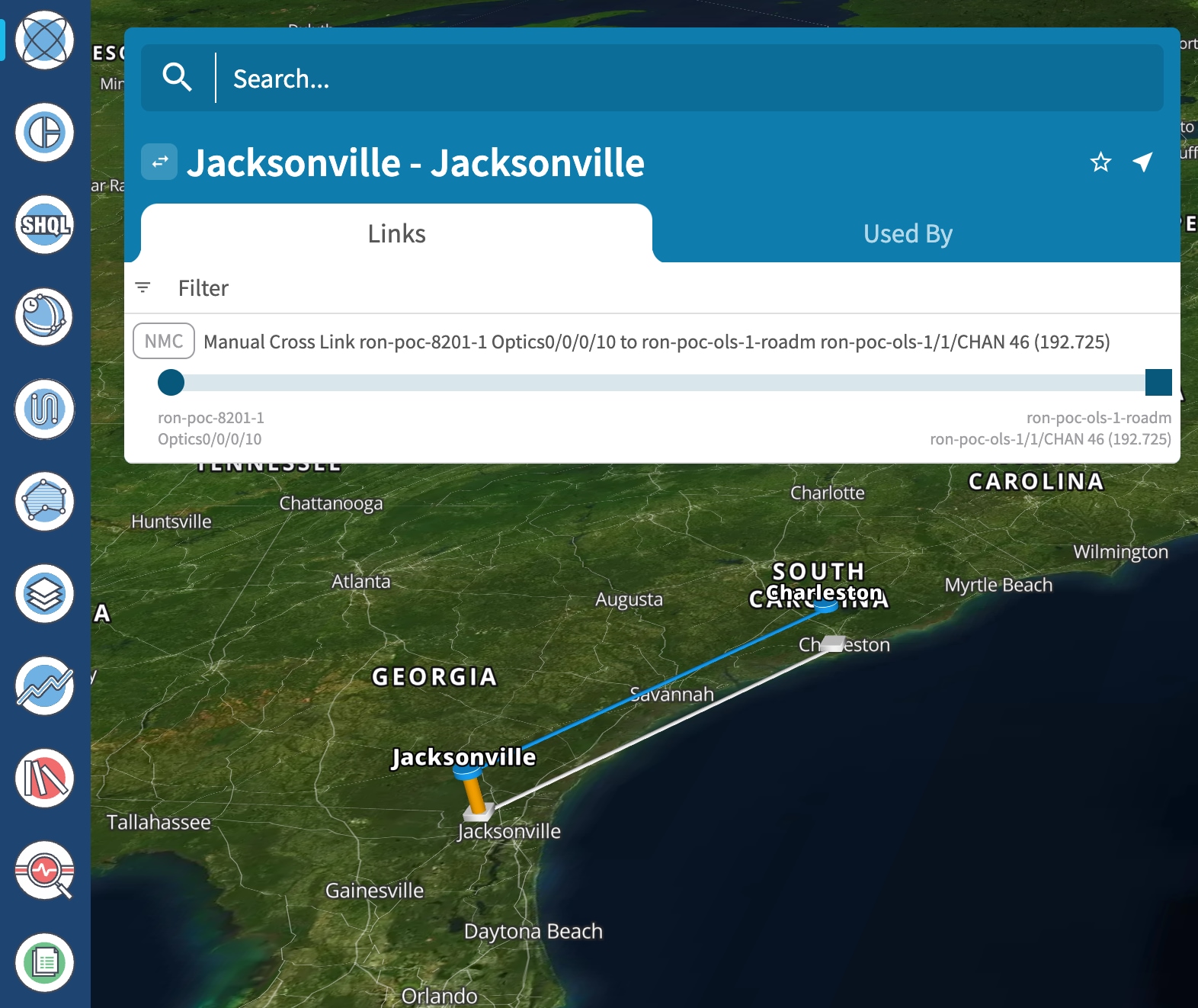
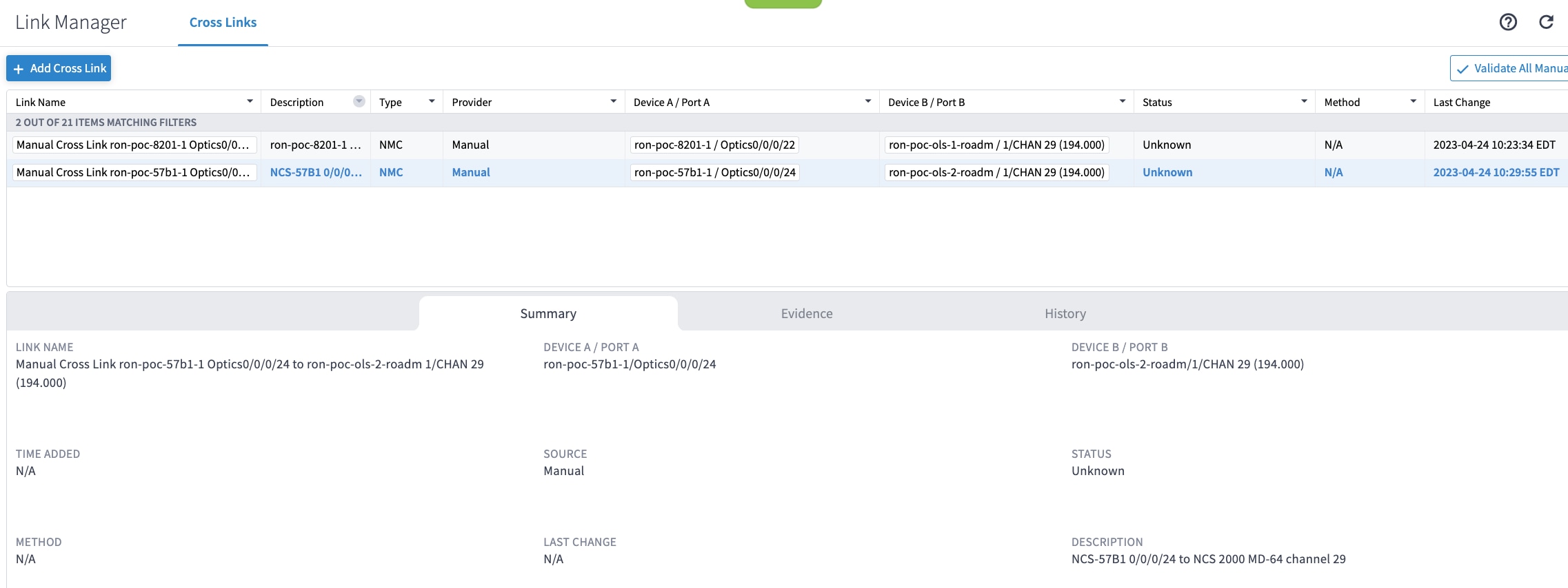
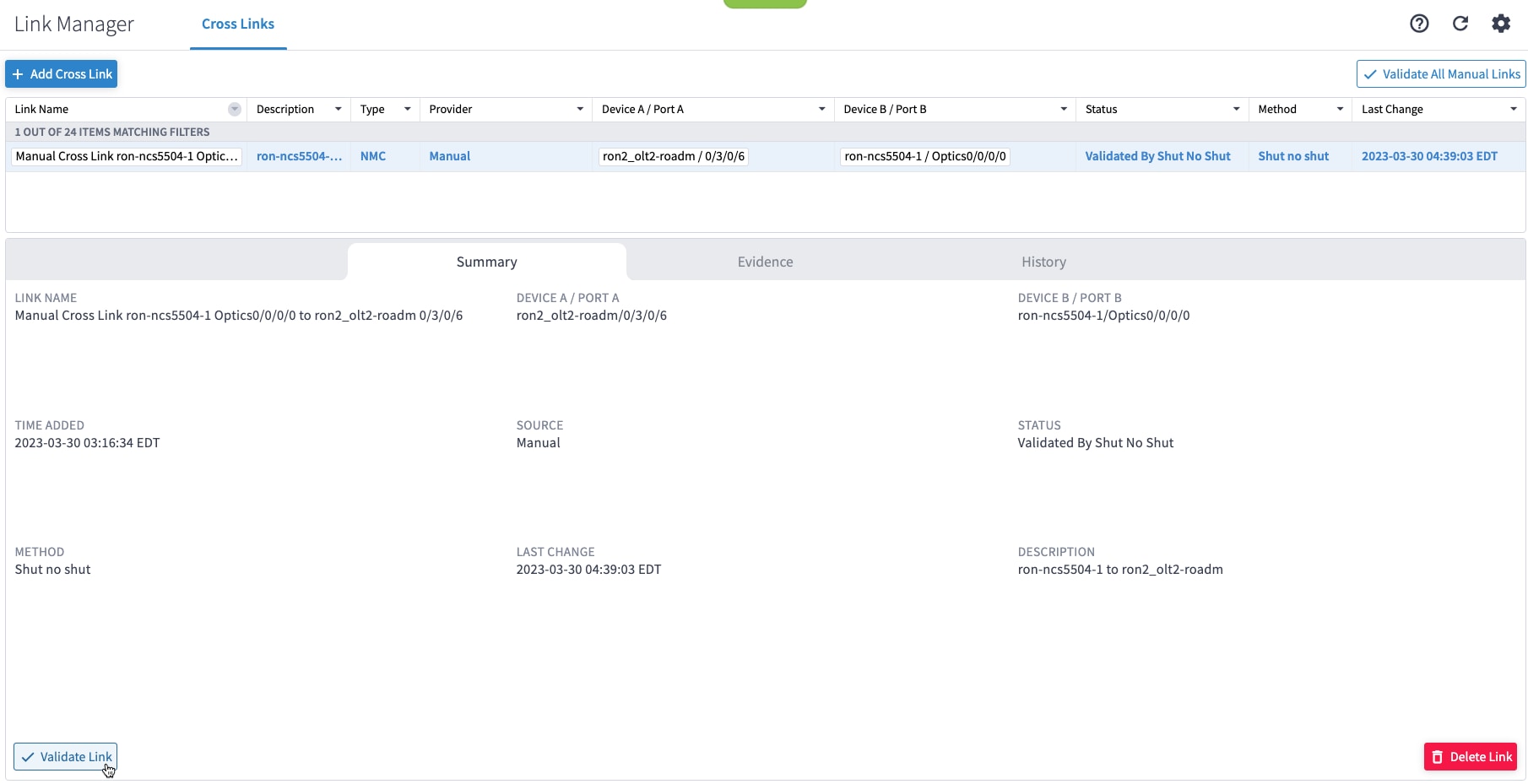
If you are performing both router and optical line system provisioning, you must create NMC Cross Links between router optics port and optical line system add-drop port. Crosswork Hierarchical Controller 8.0 in Routed Optical Networking 3.0 also supports “router only” provisioning. This type of provisioning applies optical parameters to the router optics port and IP layer parameters, but does not provision the optical line system.
|
|
Step 2 |
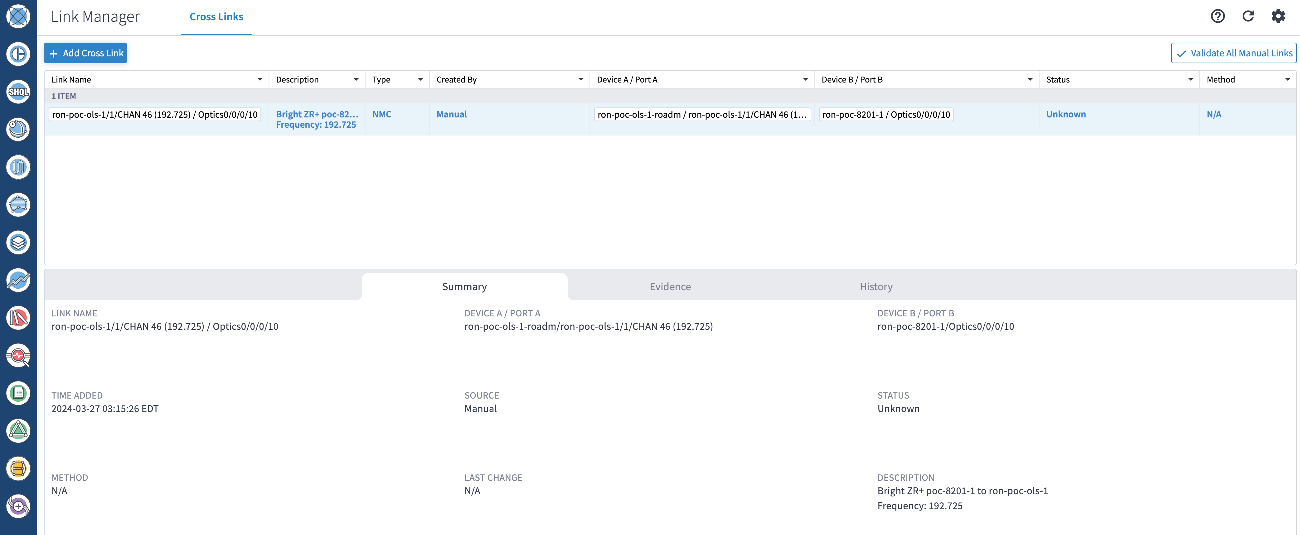
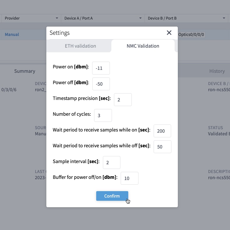
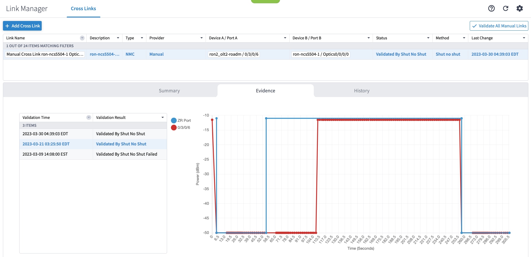
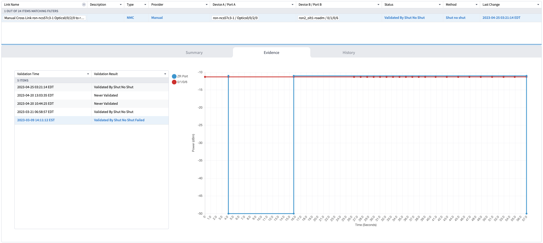
(Optional) Cross-link connectivity verification
|
|
Step 3 |
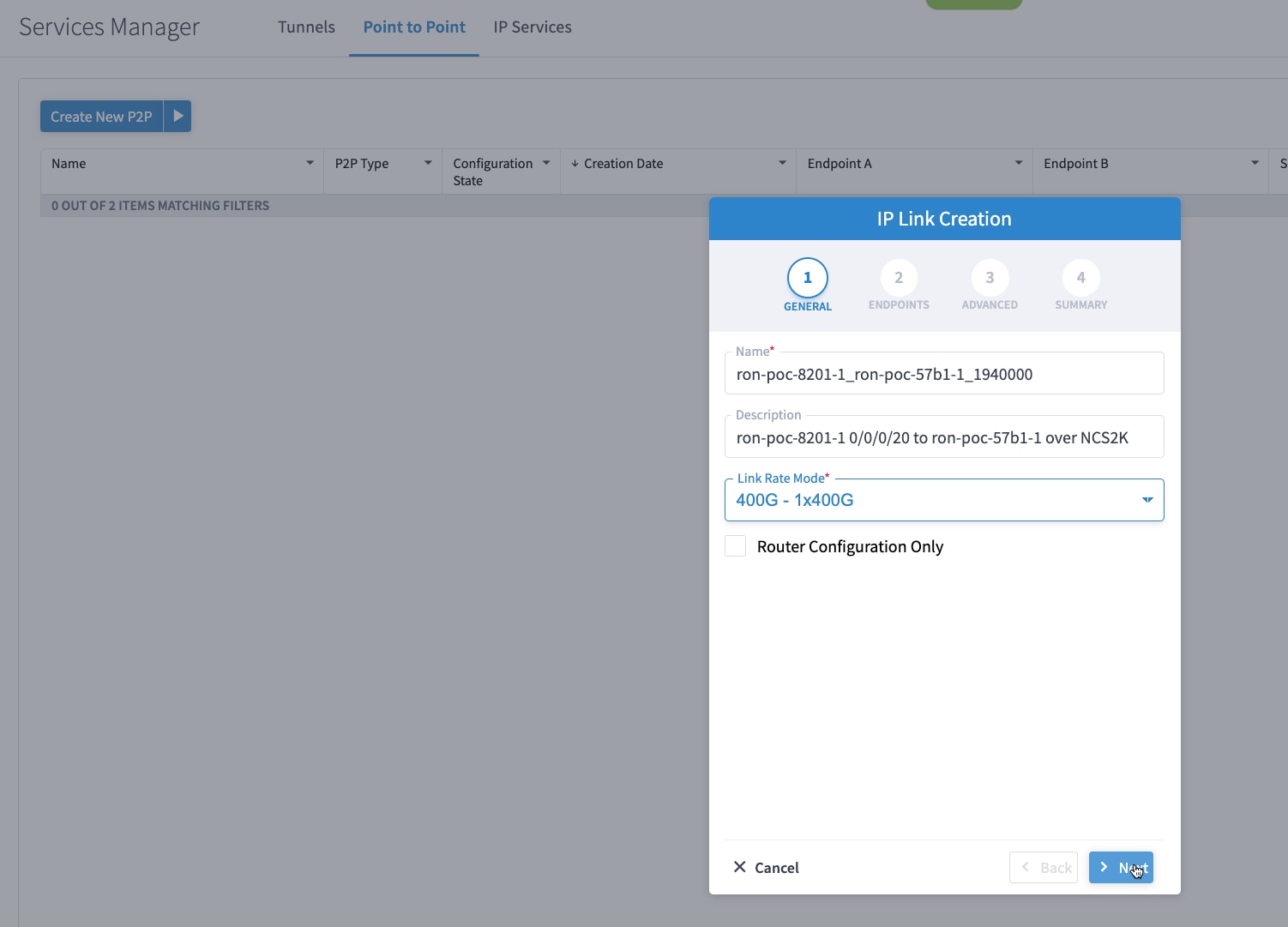
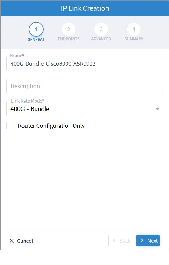
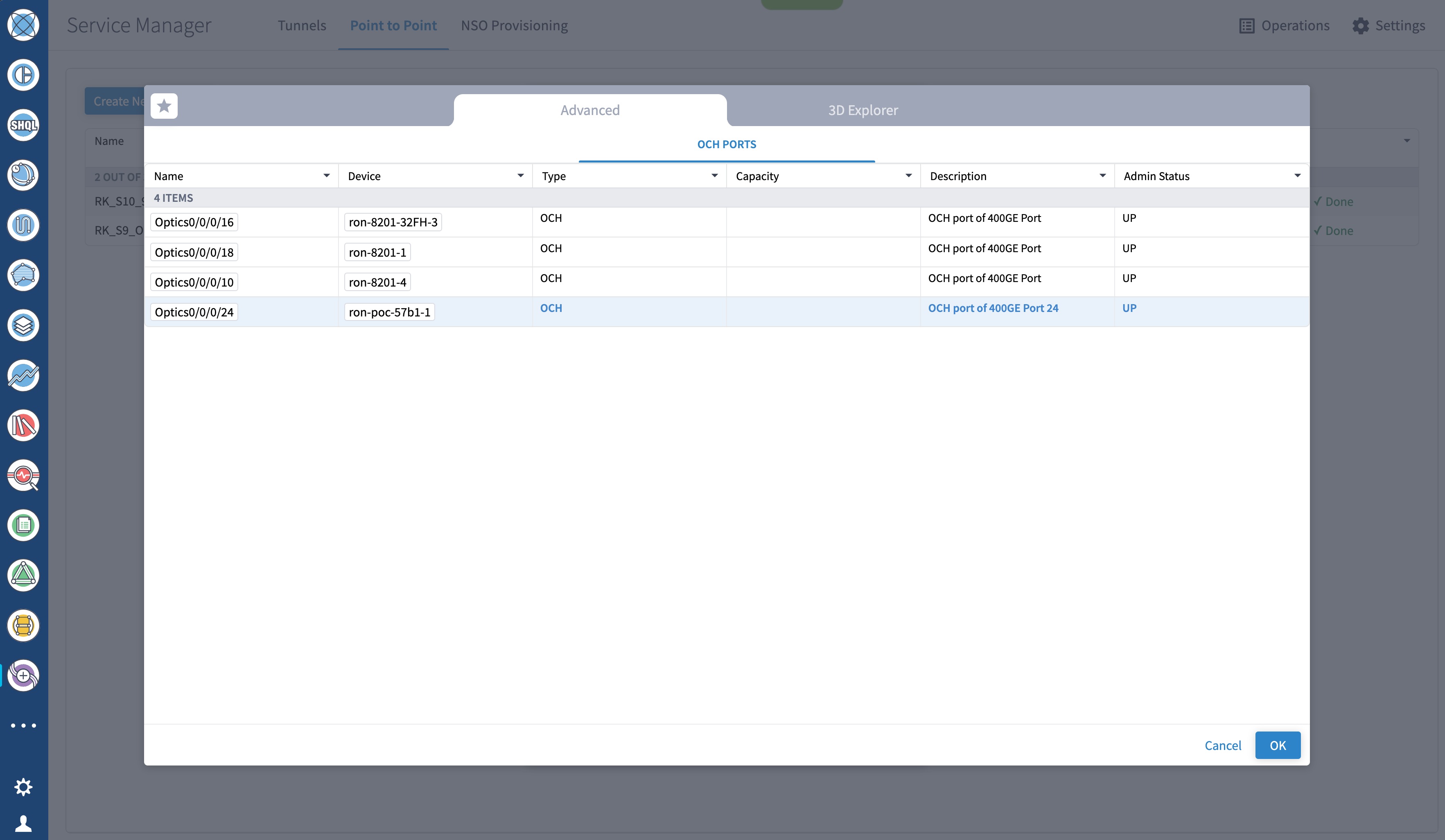
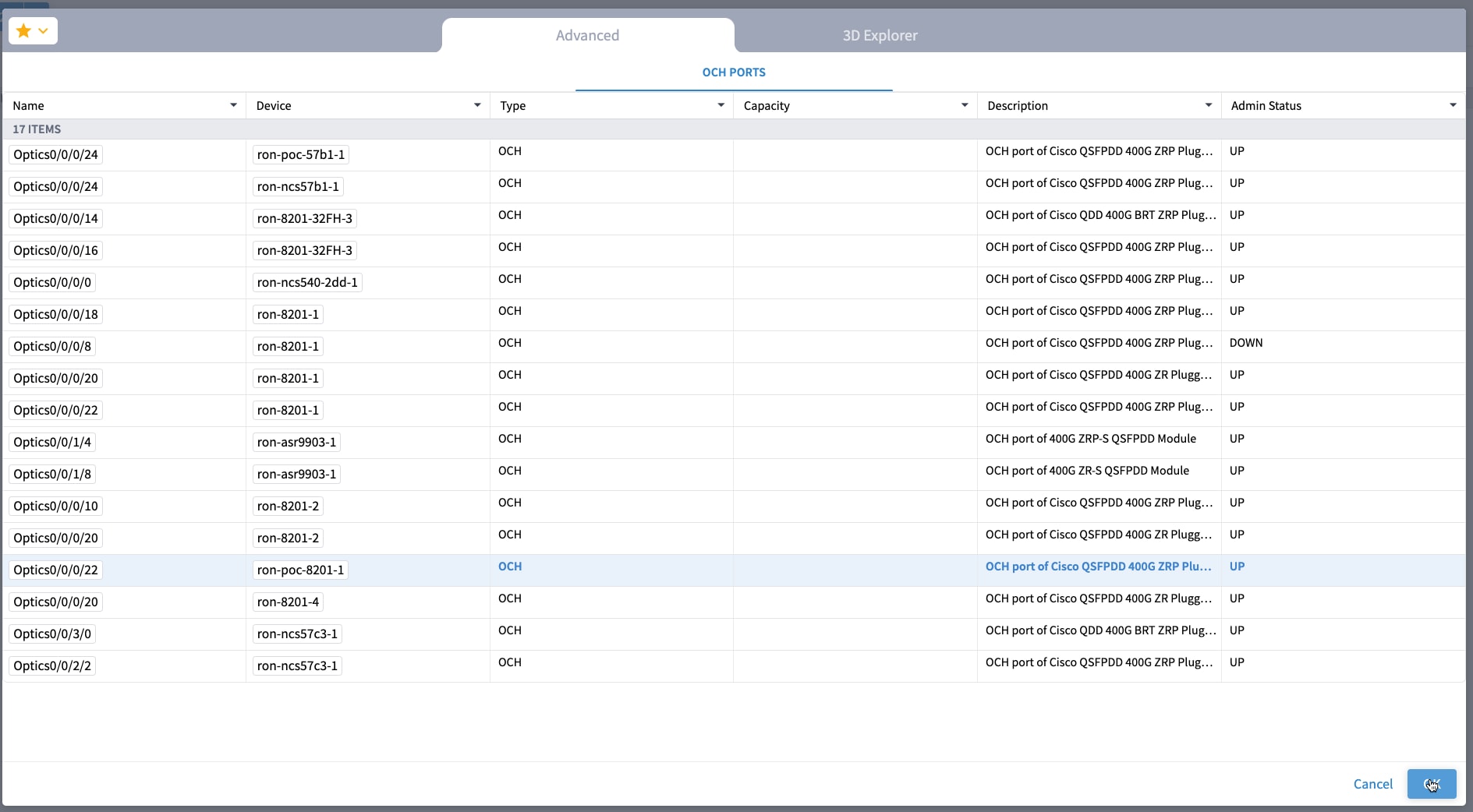
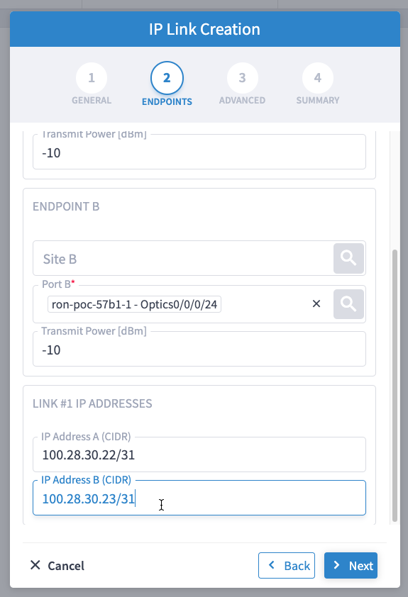
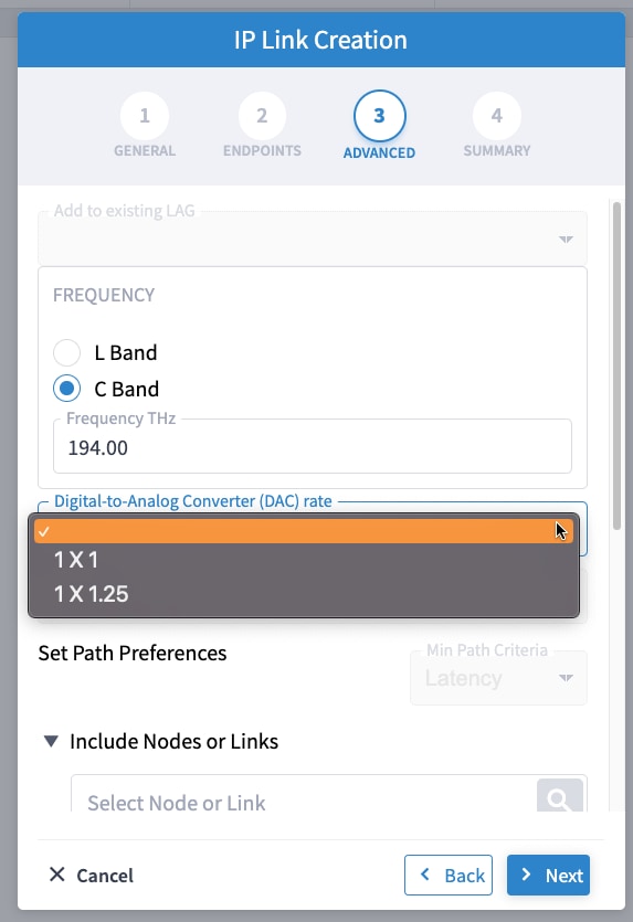
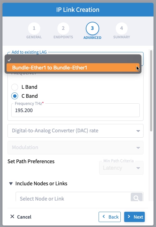
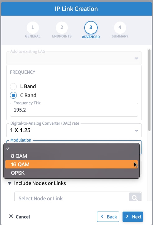
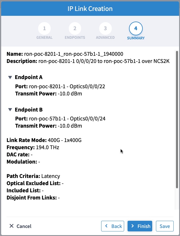
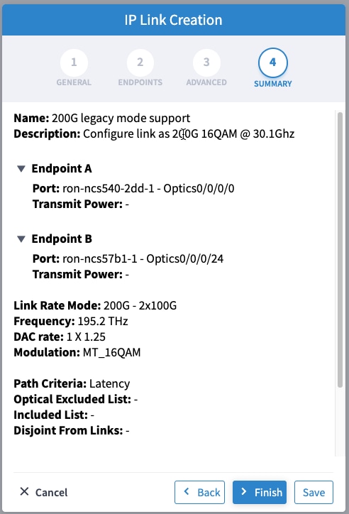
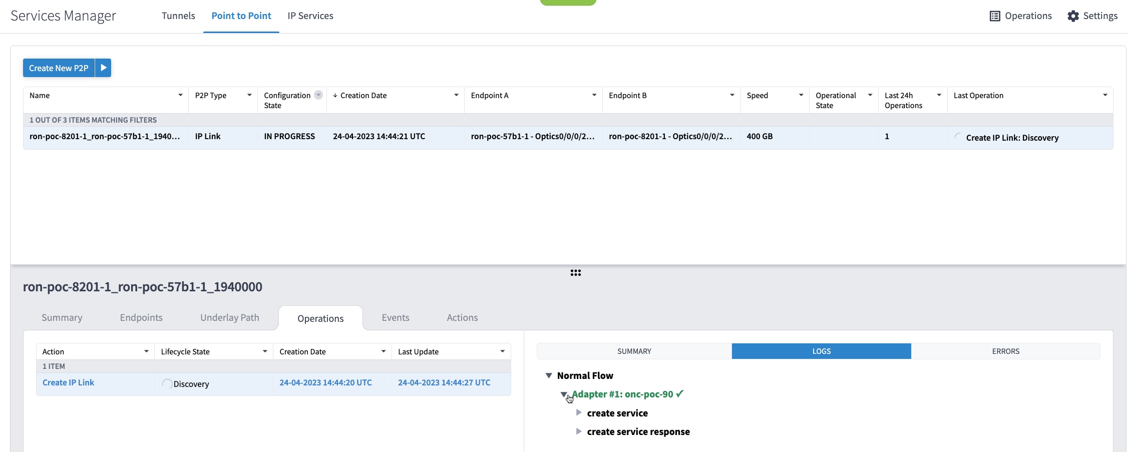
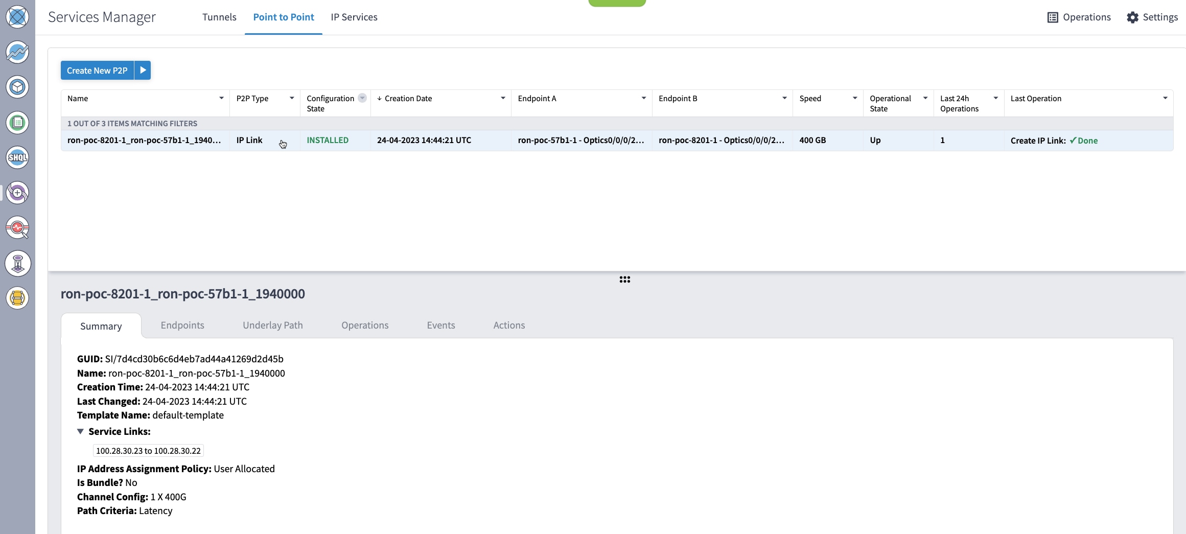
Provision the Routed Optical Networking IP link using these steps:
|
|
Step 4 |
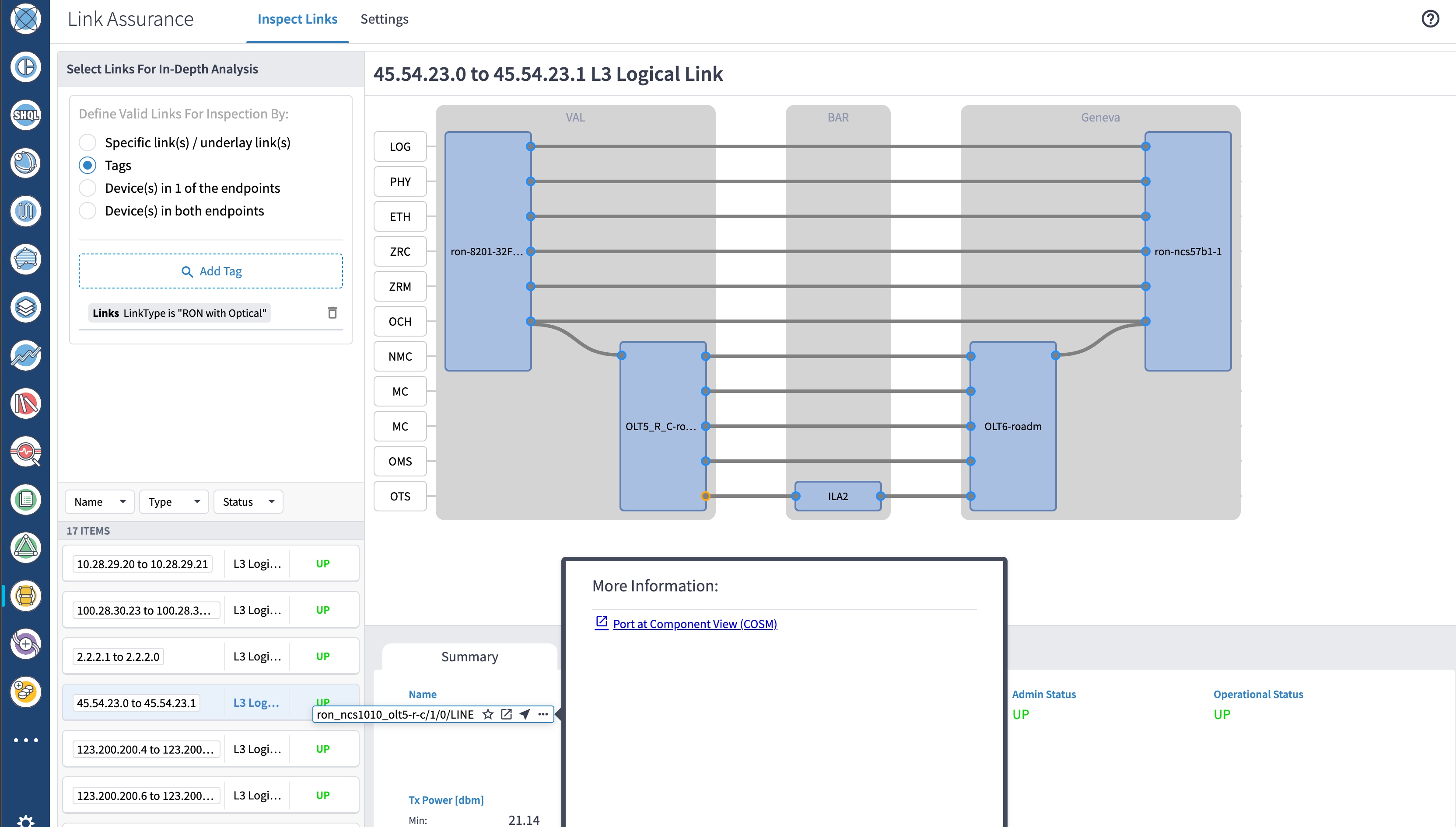
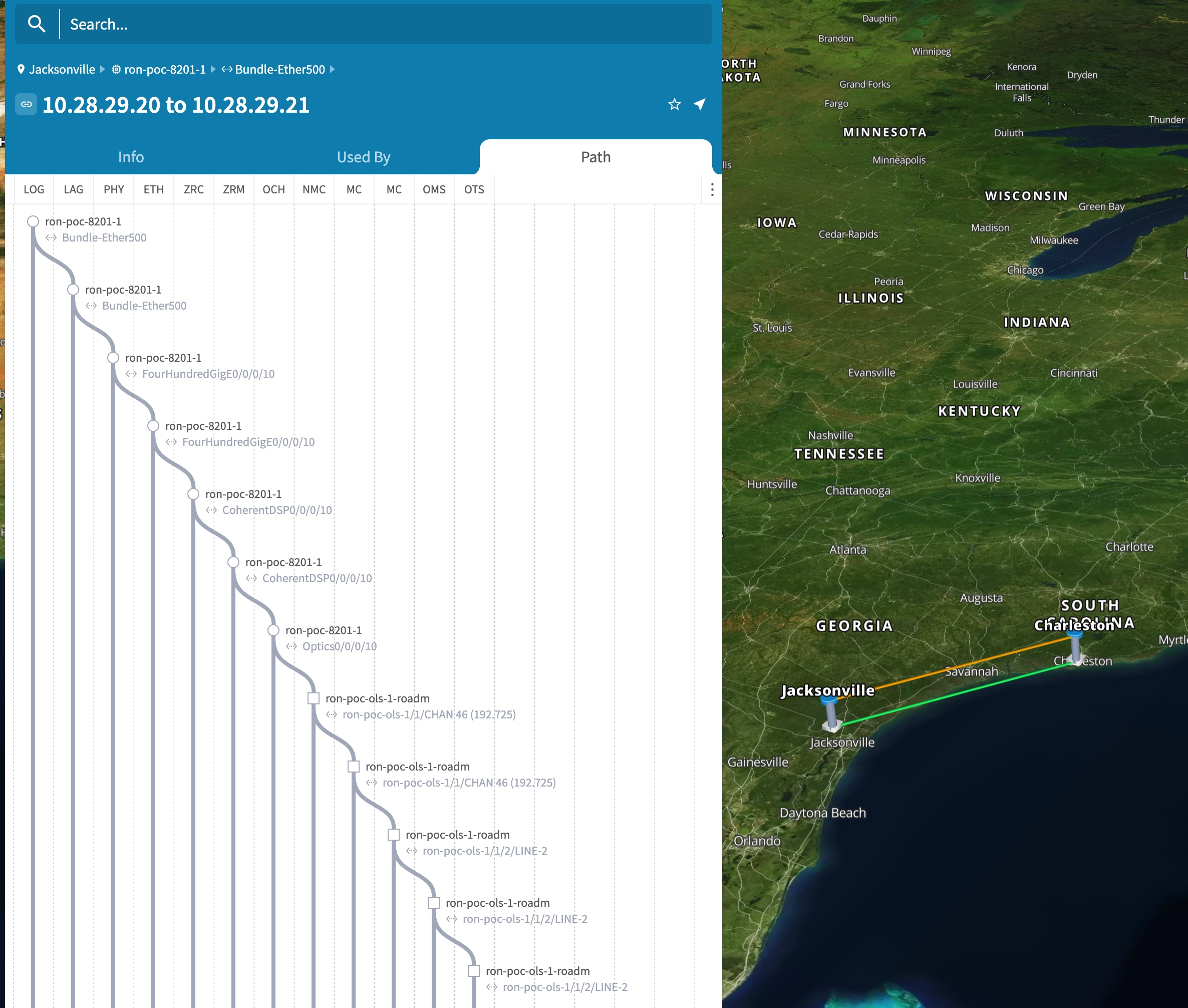
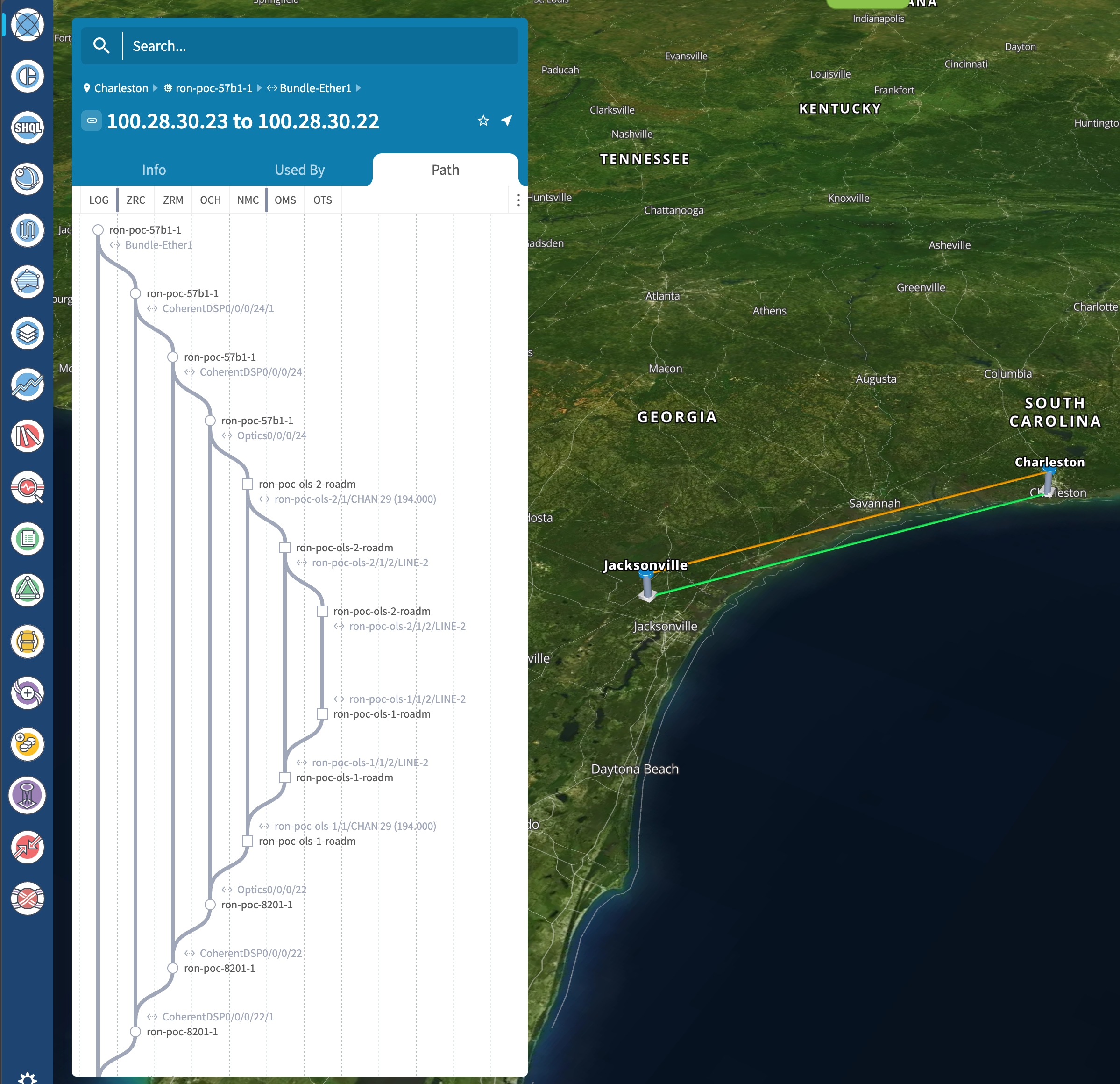
Use the Link Assurance application to verify the end-to-end path and view relevant PM data. Select a link or port to see data on the ZRM, OCH, and OTS layers. 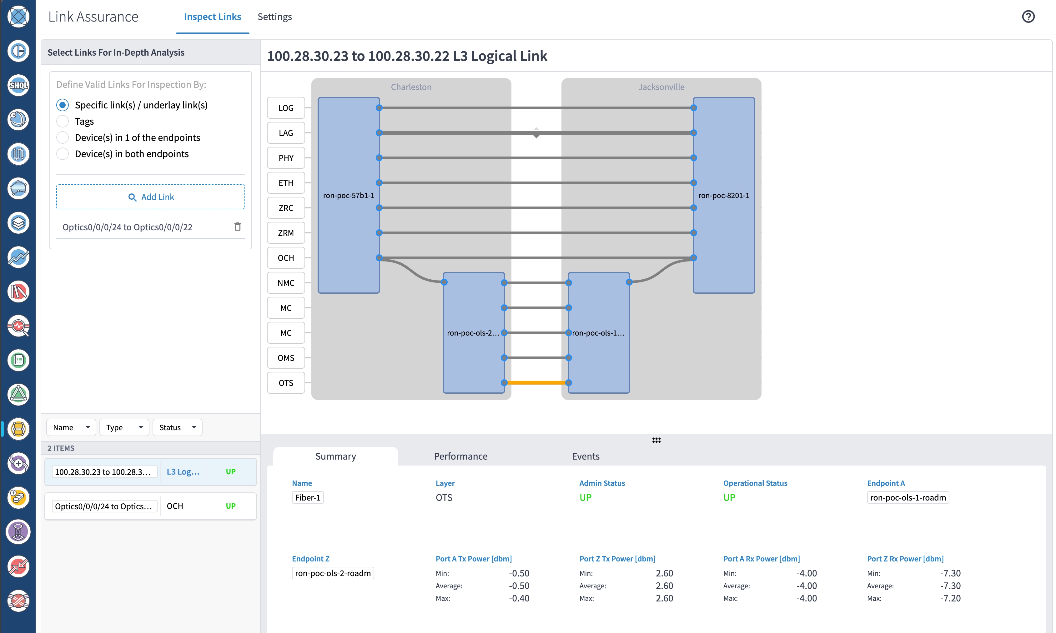
|
To monitor ZR or ZR+ optics, use EPNM and Crosswork Health Insights.
Use either CLI commands or EPNM to monitor router ZR or ZR+ optics for proper operation. See Monitor ZR or ZR+ optics using EPNM.
(Optional) Setup router ZR or ZR+ optics data collection in Crosswork Health Insights. See Monitor ZR or ZR+ optics performance Using KPIs.
To monitor NCS 1010, use Cisco Optical Network Controller and Cisco Optical Site Manager.
Follow these steps to add the 8201 router to EPNM for monitoring the PM parameters on the ZR or ZR+ optics.
|
Step 1 |
Choose Inventory > Device Management > Network Devices to add a new device to EPNM. Click Routers or a subgroup if it is already defined in the left panel. 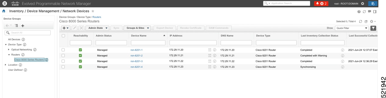 |
|
Step 2 |
Click the 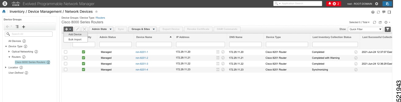 |
|
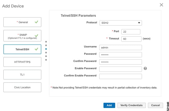
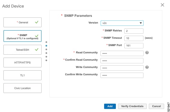
Step 3 |
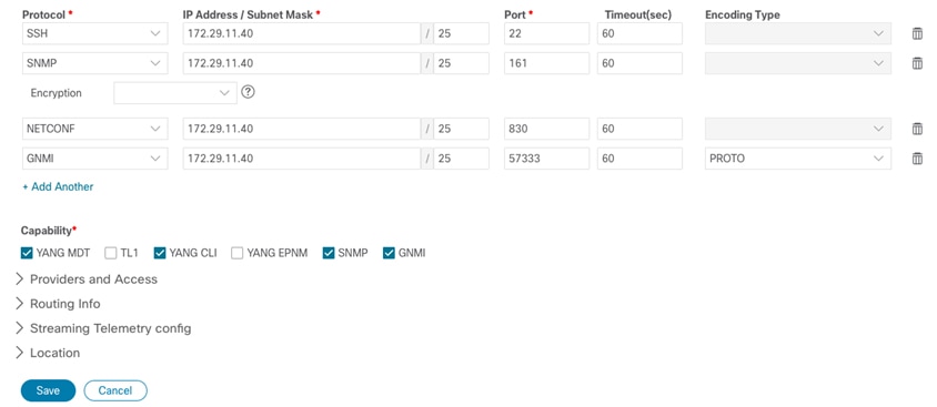
Configure the General, SNMP, and SSH parameters as shown in the figures. Then click Verify Credentials to confirm that Cisco EPN Manager can reach the device. Click Add to add the device to EPNM. 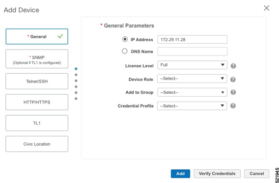
|
|
Step 4 |
Click the device name link in the Network Devices table to open the chassis view. This figure shows the chassis view of the 8201 router. 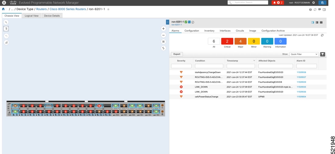
|
|
Step 5 |
Click the QSFP-DD ZR+ port to view details about that port. 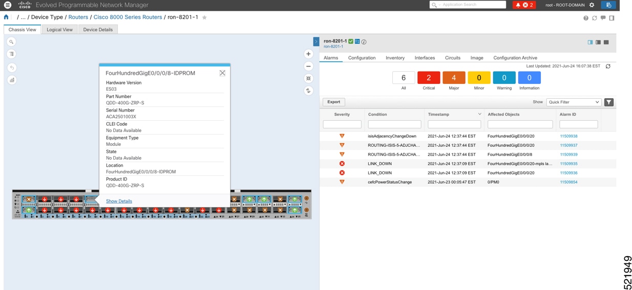 Here, you can view the port, the specific optical channel, and the CoherentDSP entities. 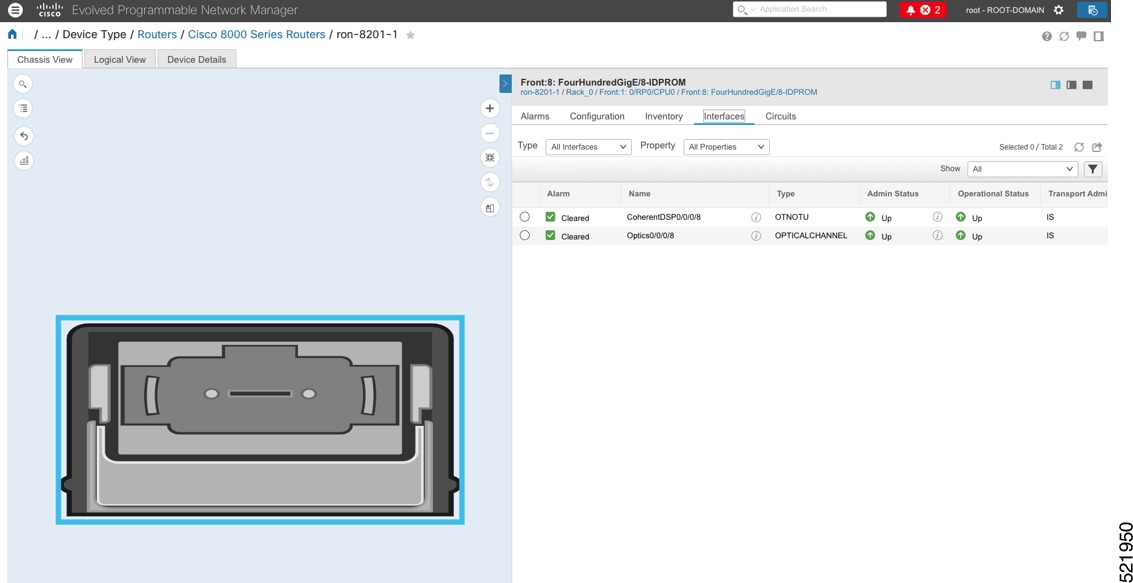 |
|
Step 6 |
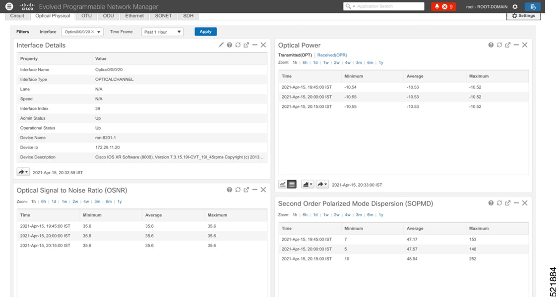
Click the additional information icon for the optical channel. Then select the Optical Physical measurement tab to display relevant optical PM values such as RX/TX signal power and OSNR values. 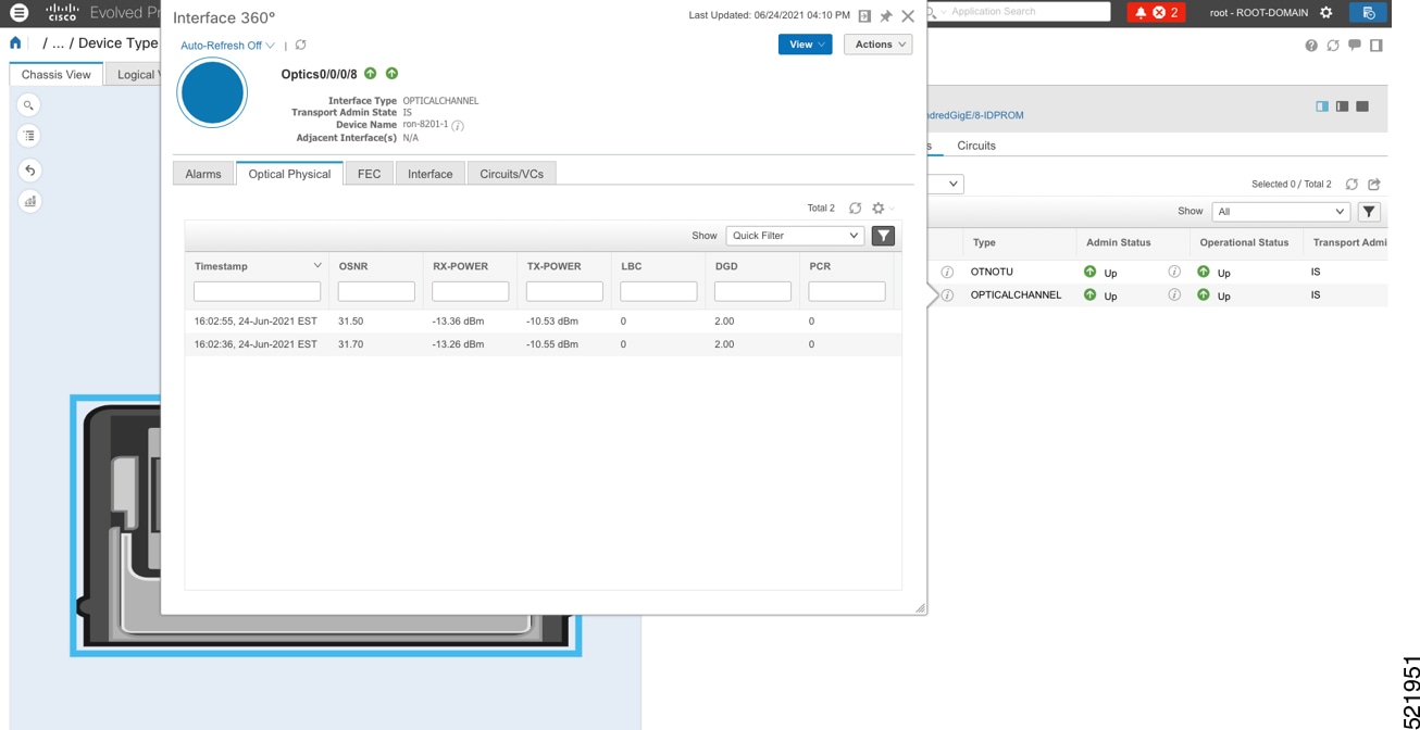 |
|
Step 7 |
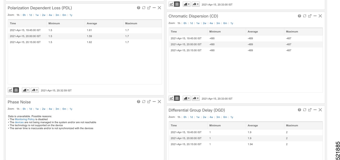
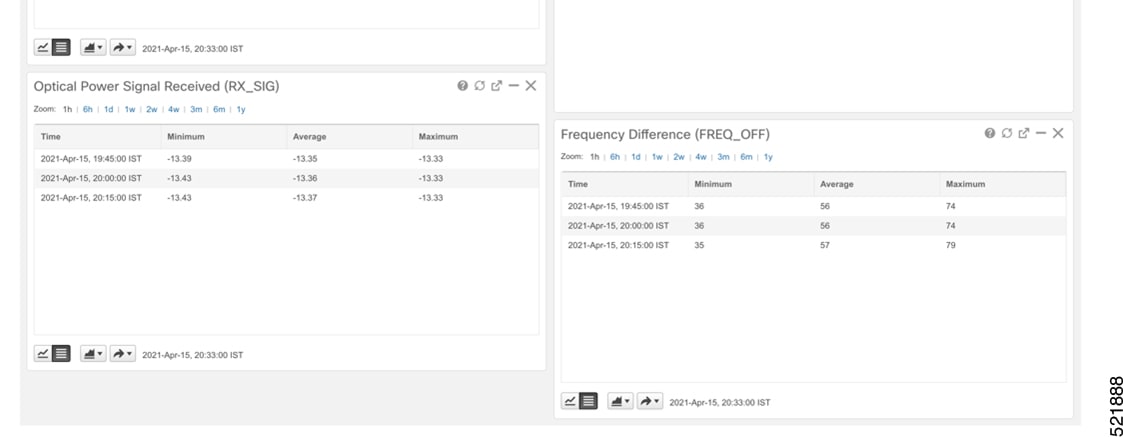
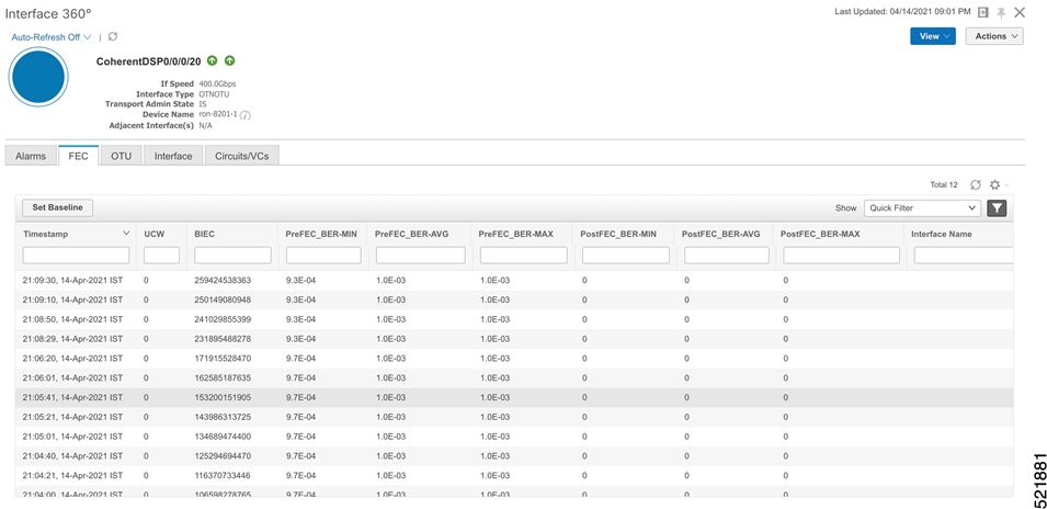
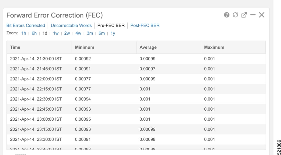
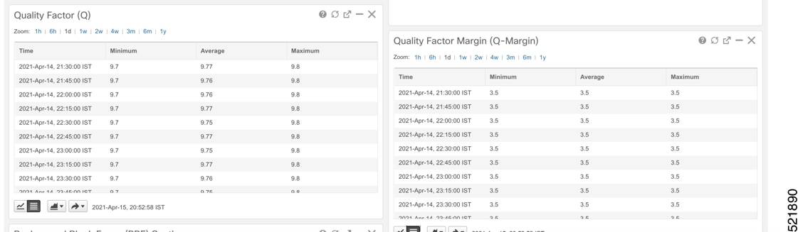
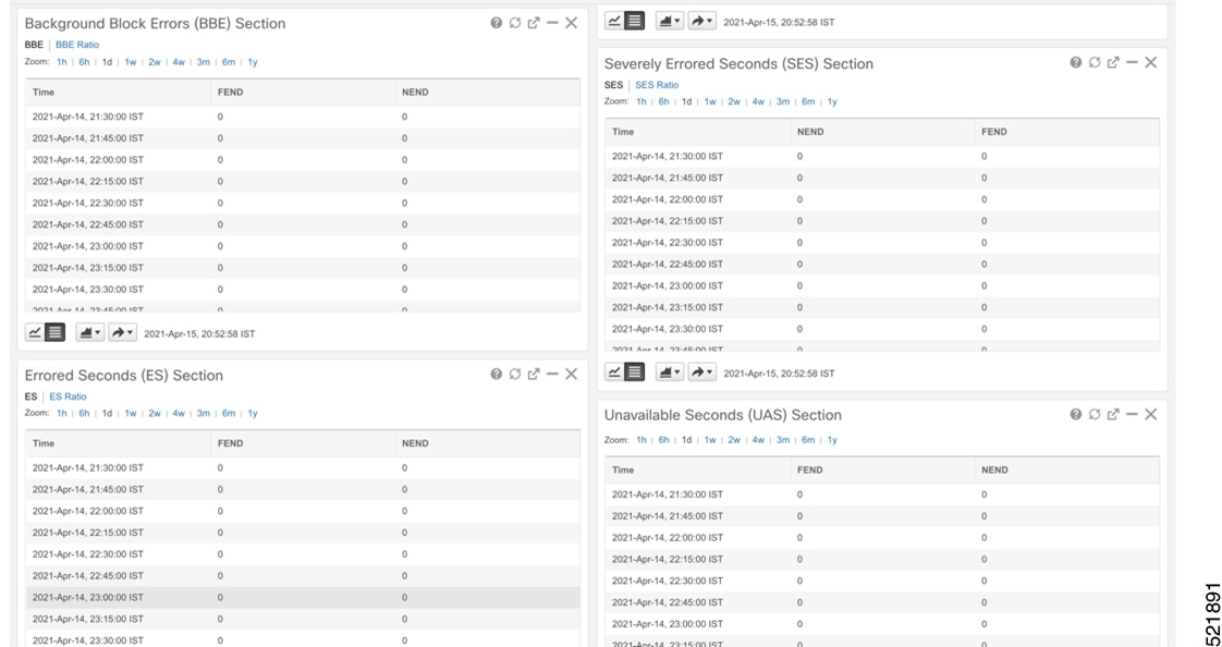
Click the additional information icon for the coherent DSP. Then select the FEC measurement tab to display relevant coherent DSP FEC statistics such as PreFEC Bit Error Rate, Bit Error Rate Count (BIEC), and Uncorrected Words (UCW). The UCW value must remain 0. These figures display EPNM monitoring data relevant to ZR or ZR+ optics, including current and historical performance. 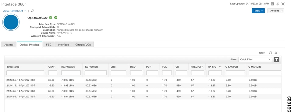
|
The purpose of the task is to enable KPI monitoring for ZR or ZR+ optics to track device health using Health Insights.
Use the KPIs supplied by Cisco to monitor specific network optics. Configure and enable KPI profiles on devices to start health monitoring.
Note |
Decide which KPIs supplied by Cisco to use for each device based on its function and the performance characteristics you want to monitor. Review the KPIs supplied by Cisco documented in List of Health Insights KPIs. The image shows the available default L1 optics KPIs. 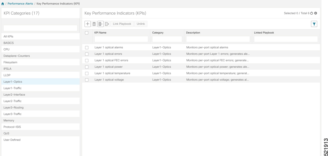 |
|
Step 1 |
Group the relevant KPIs to create a KPI Profile focused on optics. A KPI profile can have many different KPIs assigned. In this procedure, add only specific optics KPIs to the optics_profile KPI profile. 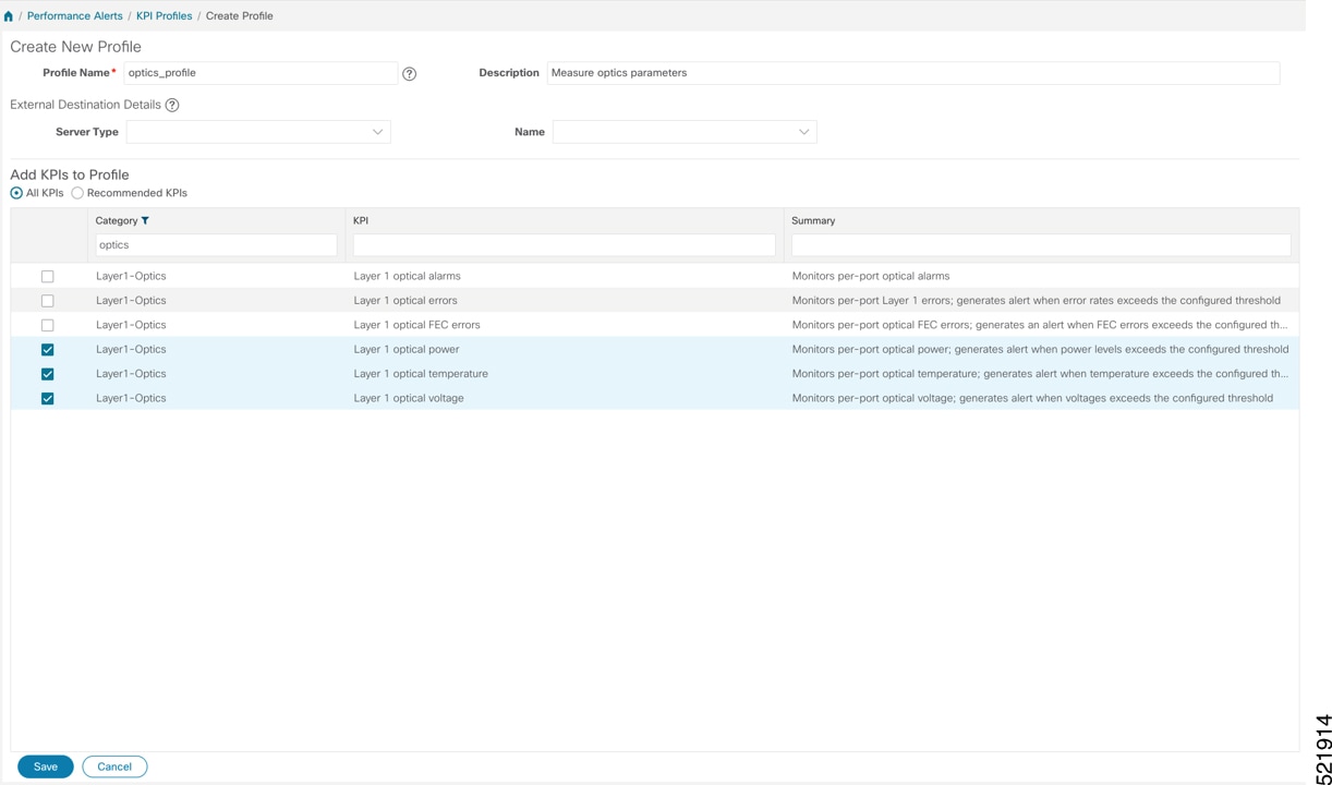
|
|
Step 2 |
Enable the appropriate KPI Profile on target devices you want to monitor.
You can select multiple nodes. The image shows the KPI profile being applied to a single node. 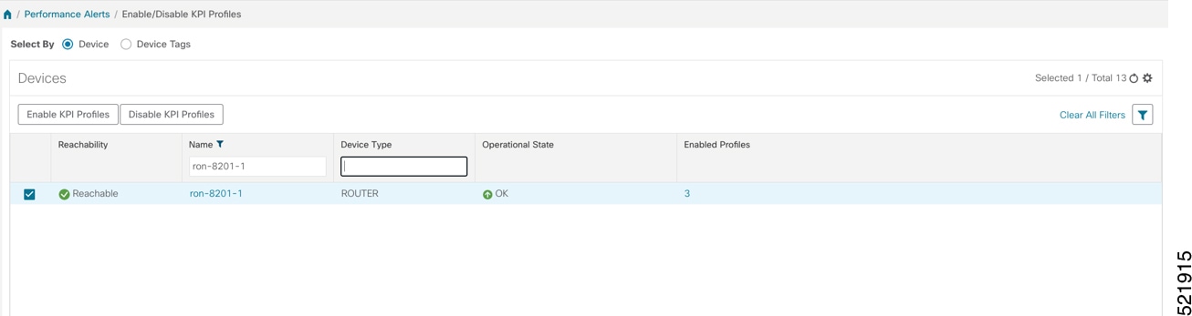 |
|
Step 3 |
Select the optics_profile KPI profile and click Next to finalize enabling the KPI for the selected devices. 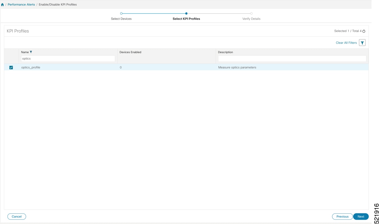 |
|
Step 4 |
Apply the configuration and click Enable to start streaming telemetry sensor data for optics KPIs. See Enable KPI Profiles on Devices. 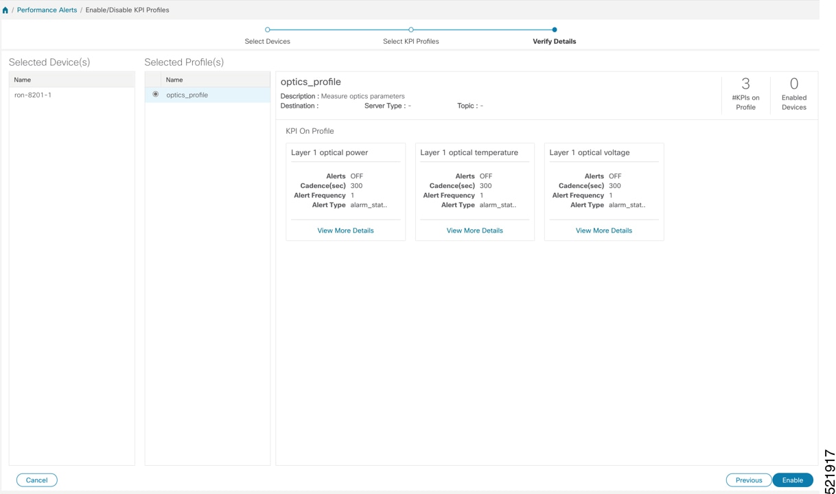 |
|
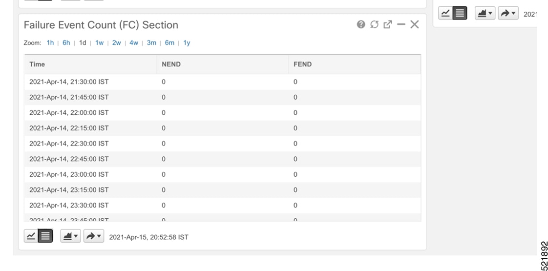
Step 5 |
View alerts from network devices as the system begins monitoring. See View Alerts for Network Devices This image shows the RX and TX power of the QDD-400G-ZR-S transceiver. 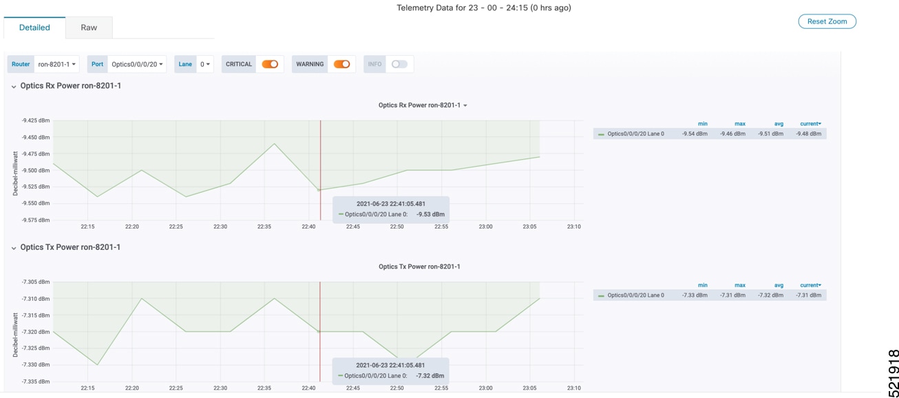 |
Devices begin streaming telemetry data for selected optics KPIs, and alerts become available in Health Insights.
The optimization phase consists of these activities:
Return to planning stage.
Continue to add or change circuits on the network to match packet demands.


 Feedback