Install and Deploy Geo Redundant Cisco Optical Network Controller

Geo redundancy

Geo redundancy involves placing physical servers in geographically different data centers to safeguard against catastrophic events and natural disasters. Cisco Optical Network Controller can now be deployed with Geo-redundancy by connecting three distinct clusters into a Geo Super cluster.

Geo Redundant Deployment in Cisco Optical Network Controller allows the integration of multiple Cisco Optical Network Controller clusters into a single Geo Supercluster, facilitating services to be automatically deployed across multiple separated regions. This feature enhances availability and resilience by providing continuous service even if one region experiences an outage. Each region functions as a separate Kubernetes cluster.

For geo-redundancy you can deploy a supercluster in a 1+1+1 configuration, which includes:

  • an active single-node (worker)

  • a standby single-node (worker)

  • a witness node (arbitrator)

The following image describes a high redundancy deployment of Cisco Optical Network Controller.

Figure 1. Cisco Optical Network Controller Deployment Infrastructure
An image describing Cisco Optical Network Controller Deployment Infrastructure.

2 VMs run Cisco Optical Network Controller and the 3rd VM acts as the arbitrator which participates in Active node selection using RAFT Algorithm.

The arbitrator runs only the OS and system services. Cisco Optical Network Controller microservices do not run on the arbitrator node. The arbitrator participates in the selection of the active node.

Releases supporting geo-redundant deployments

  • Cisco Optical Network Controller 24.3.2

  • Cisco Optical Network Controller 25.1.2

Information About Geo Redundant Deployment

Geo redundancy involves asynchronous replication of services. This setup ensures that, during failover, services can continue operating from a standby region. The Supercluster formation involves establishing connections between regions, allowing for dynamic cluster enrollment and seamless IP connectivity.

Benefits of Geo-Redundant Deployment

  • Enhanced Availability: Ensures service continuity during regional outages.

  • Resilience: Provides failover capabilities with asynchronous data replication, minimizing downtime.

Supported Scenarios

The Geo Redundant Deployment is suitable for scenarios where continuous service is critical, such as:

  • Enterprises with global operations requiring regional data centers.

  • Services demanding high availability and disaster recovery setups.

Limitations of Geo-redundant Deployments

  • Replication lag: If a switchover occurs during an ongoing operation, there's a small risk of data loss if there are network latency issues. The new active database may not have the information about the ongoing operation due to the delay. If this issue arises, retry the request. Ensure that your Eastbound network maintains low latency to minimize the risk of data loss.

    For example, during node or circuit delete operation, after Active completes the delete operation, and before a database transaction completes, a switchover or failover event occurs. The New Active continues to show the node/circuit. You must retry the delete operation.

  • Double failures: If two out of 3 nodes are down or unreachable, the remaining node becomes a standby node. You will not be able to access Cisco Optical Network Controller using the virtual IP. Bring up at least one of the nodes to bring back the Supercluster to be able to use Cisco Optical Network Controller.

  • Northbound notification loss: During a switchover or failover, the virtual IP interface is unreachable for a short amount of time. During this connectivity disturbance, event notifications to any hierarchical controllers are lost. In Releases 24.x.x and 25.x.x, Cisco Optical Network Controller does not support notification replay.

  • PM Loss: The 15-minutes and 1-day PM buckets during a switchover or failover event is lost. The next PM bucket after the switchover or failover alarm clears, continues to work as expected.

  • SWIM Job Failures: Any SWIMU ad hoc device configuration backup jobs that are in progress at the time of a switchover or failover move to the Failed state. You must create the job again to trigger backups. Scheduled SWIM jobs fail if they are in progress at the time of a switchover or failover. Scheduled jobs continue to run according to the schedule.

  • Data Corruption during Restore Operations: Cisco Optical Network Controller supports database restore operations only on the active node. If a switchover or failover happens when a restore operation is ongoing, the data may get corrupted. In case of data corruption, Cisco Optical Network Controller services do not come back to the ready state. You must perform a restore again to recover the cluster.

  • Switchover and Failover Duration: You must verify that all micro-services on both active and standby nodes are in ready state by running the sedo system status command. A manual switchover should be triggered only when all services are confirmed to be in ready state. Cisco Optical Network Controller requires approximately 4 minutes to complete the switchover/failover procedure. During this period, do not initiate another switchover. After a node failover, the failed node requires approximately 15–20 minutes to be prepared for a second switchover/failover. A double failure may occur if a second switchover or failover occurs before the VMs are ready. When TAPI is enabled, the switchover time exceeds 4 minutes, depending on the scale of devices and circuits involved.

  • Web UI Down During Failover: When a failover occurs, the WebUI is not accessible until the failover process completes. This delay is approximately 4 minutes. Access the web UI after 4 minutes by refreshing the browser. To confirm a failover, go to the Alarms app and look for the switchover alarm in Alarm History.

  • Incomplete Circuit Configurations: If a network circuit is only partially set up with a few cross-connects and a switchover or failover occurs before database replication between active and standby nodes are complete, the system creates incomplete or unconnected configurations. You must manually clean them up using Cisco Optical Site Manager.

Installation Files

Cisco Optical Network Controller is released with a single VMware OVA file distribution. OVA is a disk image deployed using vCenter on any ESXi host. This OVA packages together several components including a file descriptor (OVF) and virtual disk files containing a basic operating system and the Cisco Optical Network Controller installation files. OVA can be deployed using vCenter on ESXi hosts supporting Standalone (SA) or supercluster deployment models.


Note


During the OVF deployment, the deployment gets aborted if there is an internet disconnection.


Before you begin

  • Infrastructure: VMware ESXi 7.0 and later releases, vCenter 7.0 and later releases, and adequate resources for VM deployment.


    Attention


    Upgrade to VMware vCenter Server 8.0 U2 if you are using VMware vCenter Server 8.0.2 or VMware vCenter Server 8.0.1.


    • You need a VM for each cluster. You need 3 clusters.

    • We recommend the VMs must be running at 3 different zones or regions to avoid a single point of failure. You need two out of 3 VMs up for Cisco Optical Network Controller to work. If you have two VMs in the same location, this location can become a single point of failure.

    • Depending on your scale needs, you can choose from one of the 3 profiles from the following table.

      Profile CPU (in cores) Memory (GB)β€― Disk (TB)
      Worker Node Arbitrator Node Worker Node Arbitrator Node
      XS 16

      8

      64

      32

      0.8β€―
      S 32

      8

      128

      32

      1.5β€―
      M 48

      8

      256

      32

      1.5
    • vCPU to Physical CPU Core Ratio: We support a vCPU to Physical CPU core ratio of 2:1 if hyperthreading is enabled and the hardware supports hyperthreading. Hyperthreading is enabled by default on Cisco UCS servers that support hyperthreading. In other cases, the vCPU to Physical CPU core ratio is 1:1.

    • Accept the Self-Signed Certificate from the ESXi host.

      1. Access the ESXi host using your web browser.

      2. If you receive a security warning indicating that the connection is not private or that the certificate is not trusted, proceed by accepting the risk or bypassing the warning.

  • Network: Before installing Cisco Optical Network Controller, create three networks.

    • Control Plane Network

      The control plane network helps in the internal communication between the deployed VMs within a cluster.

    • VM Network or Northbound Network

      The VM network is used for communication between the user and the cluster. It handles all the traffic to and from the VMs running on your ESXi hosts. This network is the public network through which the web UI is hosted. Cisco Optical Network Controller uses this network to connect to COSM devices using Netconf/gRPC.

    • Eastbound Network

      The Eastbound Network helps in the internal communication between the deployed VMs within a supercluster. The active and standby nodes use this network to sync their databases. The postgres database is replicated across active and standby. MinIO is replicated on the arbitrator also.

      Bandwidth requirement: The Eastbound network should have a bandwidth of 1 Gbps and a latency less than 100 ms.

      You can configure the Eastbound network to be a flat Layer 2 network or an L2VPN where the Eastbound IPs of all the nodes are in the same subnet. If your Eastbound IPs are in different subnets, you must configure static routing between your nodes for the eastbound network.

  • You must create three network interfaces within vCenter (Control Plane, Northbound, Eastbound) with specific IP configurations for each node in a 1+1+1 supercluster.

    After adding the ESXi host to vCenter, create the Control Plane, Northbound, and Eastbound Networks before deploying. To create the Control Plane, Northbound, and Eastbound networks, perform the following steps:


    Restriction


    Do not configure the Control Plane, Northbound and Eastbound networks in the same subnet or vlan segment. Use separate subnets and vlan segments for these networks.


    1. Log in to the vCenter and Select the ESXi Host that you want to deploy GeoHA on.

      Select Configure > Networking > Virtual Switches > Add Networking

      screenshot
    2. In Select connection type, choose Virtual Machine Port Group for a Standard Switch and click Next.

    3. In Select target device , select New Standard Switch (MTU 1500) and click Next.

    4. In Create a Standard Switch, click Next, and confirm There are no active physical network adapters for the switch. for the Control Plane Network. For Northbound and Eastbound networks, choose the relevant adapter.

    5. In Connection settings choose the relevant network label (Control Plane, Northbound, or Eastbound) and select the relevant VLAN ID. Click Next.

    6. In Ready to complete, review your configuration and click Finish.

  • Storage: SSDs to meet the disk write latency requirement of ≀ 100 ms.

  • BGP is used for traffic routing to the virtual IP from the various locations. You must configure the BGP router and configure the nodes as neighbors in the router. Contact your network admin to set up your BGP router.

  • You need 3 separate VMs with separate Eastbound Network, Northbound network, and Control Plane network.

  • You cannot remove nodes from or change roles of a cluster after a cluster joins a supercluster.

This table lists the default port assignments.

Table 1. Communications Matrix
Traffic Type Port Description
Inbound TCP 22 SSH remote management
TCP 8443 HTTPS for UI access
Outbound TCP 22 NETCONF to routers
TCP 389 LDAP if using Active Directory
TCP 636 LDAPS if using Active Directory
Customer Specific HTTP for access to an SDN controller
User Specific HTTPS for access to an SDN controller

TCP 3082, 3083,

2361, 6251

TL1 to optical devices

Eastbound

TCP 10443

Supercluster join requests

UDP 8472

VxLAN

syslog User specific TCP/UDP

Control Plane Ports (Internal network between cluster nodes, not exposed)

TCP 443 Kubernetes
TCP 6443 Kubernetes
TCP 10250 Kubernetes
TCP 2379 etcd
TCP 2380 etcd
UDP 8472 VXLAN
ICMP Ping between nodes (optional)

Procedure


Step 1

Right-click the ESXi host in the vSphere client screen and click Deploy OVF Template.

Step 2

In the Select an OVF template screen, select the URL radio button for specifying the URL to download and install the OVF package from the Internet or select the Local file radio button to upload the downloaded OVA files from your local system and click Next.

Figure 2. Select an OVF Template
screenshot

Step 3

In the Select a name and folder screen, specify a unique name for the virtual machine Instance. From the list of options, select the location of the VM to be used and click Next.

Note


The data center and location of for each virtual machine for Geo Redundant deployment must be chosen according to the location where you want to deploy each VM. The compute resources in the next step are shown based on the selection in this screen.

Figure 3. Select a name and folder
screenshot

Step 4

In the Select a compute resource screen, select the destination compute resource on which you want to deploy the VM and click Next.

Figure 4. Select a Compute Resource
screenshot

Note


While selecting the compute resource the compatibility check proceeds till it completes successfully.

Step 5

In the Review details screen, verify the template details and click Next.

Figure 5. Review Details
screenshot

Step 6

In the Select storage screen, select the virtual disk format based on provision type requirement. VM Storage Policy is set as Datastore Default and click Next. Select the virtual disk format as Thin Provision.

Figure 6. Select Storage
screenshot

Step 7

In the Select networks screen, select the Control Plane, Eastbound, and Northbound networks you created for each VM and click Next.

Figure 7. Select Networks
screenshot

Step 8

In the Customize template screen, set the values using the following table as a guideline for deployment.

Figure 8. Customize Template
screenshot
screenshot
screenshot

For the arbitrator node, choose arbitrator as the Supercluster Cluster Role.

Table 2. Customize Template
Key Values

General

Instance Hostname <instance-name>

Must be a valid DNS name per RFC1123.1.2.4.

  • Contain at most 63 characters.

  • Contain only lowercase alphanumeric characters or '-'

  • Start with an alphanumeric character.

  • End with an alphanumeric character.

SSH Public Key

<ssh-public-key>. Used for SSH access that allows you to connect to the instances securely without the need to manage credentials for multiple instances. SSH public key must be a ed25519 key. See SSH Key Generation.

Node Config

Node Name

Use the same name as Instance Hostname

Initiator Node Select the check box
Supercluster Cluster Index

Set to 1 (active cluster), 2 (standby cluster), or 3 (arbitrator).

Supercluster Cluster Name

Set to cluster1 (active cluster), cluster2 (standby cluster), or cluster3 (arbitrator).

Data Volume Size (GB)

Configure data volume according to the VM profile.

NTP Pools (comma separated)

(Optional) A comma-separated list of the NTP pools. For example, debian.pool.ntp.org

NTP Servers (comma separated)

(Optional) A comma-separated list of the NTP servers.

Cluster Join Token

Autogenerated value. Leave as is.

Control Plane Node Count 1
Control Plane IP (ip[/subnet]) <Private IP for the Instance> Control Plane Network
Initiator IP <Same IP as Control Plane> Control Plane Network

Northbound Interface

Protocol Static IP
IP (ip[/subnet]) - if not using DHCP <Public IP for the Instance> Northbound Network
Gateway - if not using DHCP <Gateway IP for the Instance> Northbound Network
DNS DNS Server IP

Eastbound Interface

Protocol Static IP
IP (ip[/subnet]) - if not using DHCP

< IP for the Instance> Eastbound Network

Gateway - if not using DHCP <Gateway IP for the Network> Eastbound Network
DNS DNS Server IP

Initiator Config

Northbound Virtual IP Type L3

Cluster Config

Northbound Virtual IP Virtual IP for the SuperCluster
Supercluster Cluster Role

worker for primary and secondary nodes

arbitrator for arbitrator node

Arbitrator Node Name a unique node name.

Attention

 
  • The arbitrator node name must not the same as any node in the supercluster. This field must not be the same as the node name of the arbitrator node either.

  • The arbitrator node name must be the same across all nodes in the supercluster.

Restriction


Do not configure the Northbound and Eastbound networks in the same subnet or vlan segment. Use separate subnets and vlan segments for these networks.

Step 9

In Review the details screen, review all your selections and click Finish. To check or change any properties from the review screen anytime, before clicking Finish, click BACK to go back to the previous screen, Customize template, to make necessary changes.

Figure 9. Ready to Complete
screenshot screenshot

Step 10

Perform the previous steps 3 times to create the two worker node VMs (active and standby), and the arbitrator node VM.

Attention

 
  • You can create the other nodes at a different data center, host, or vCenter instance according to your requirements. Ensure Eastbound and Northbound network connectivity between the nodes.

  • Upon activation of the virtual machine (VM), it is designed not to respond to ping requests. However, you can log in using SSH if the installation has been completed successfully.


What to do next

Set Up the Supercluster

Set Up the Supercluster

Before you begin

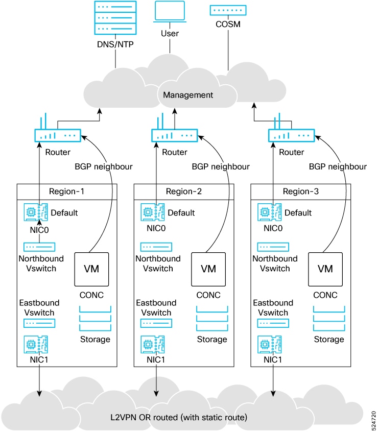
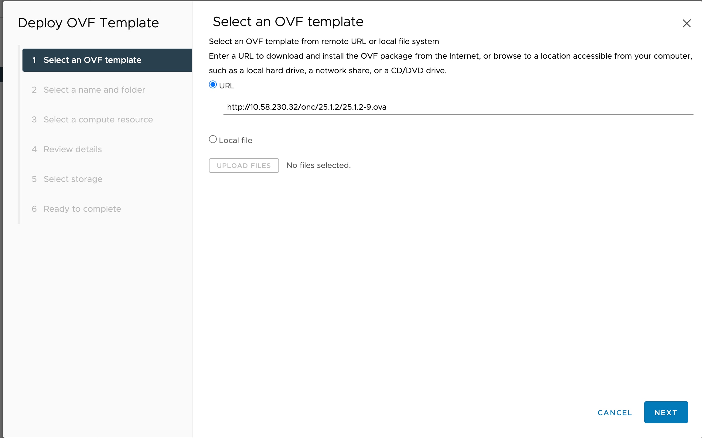
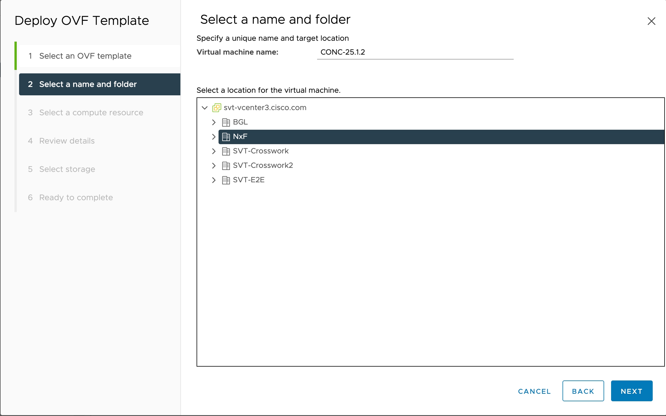
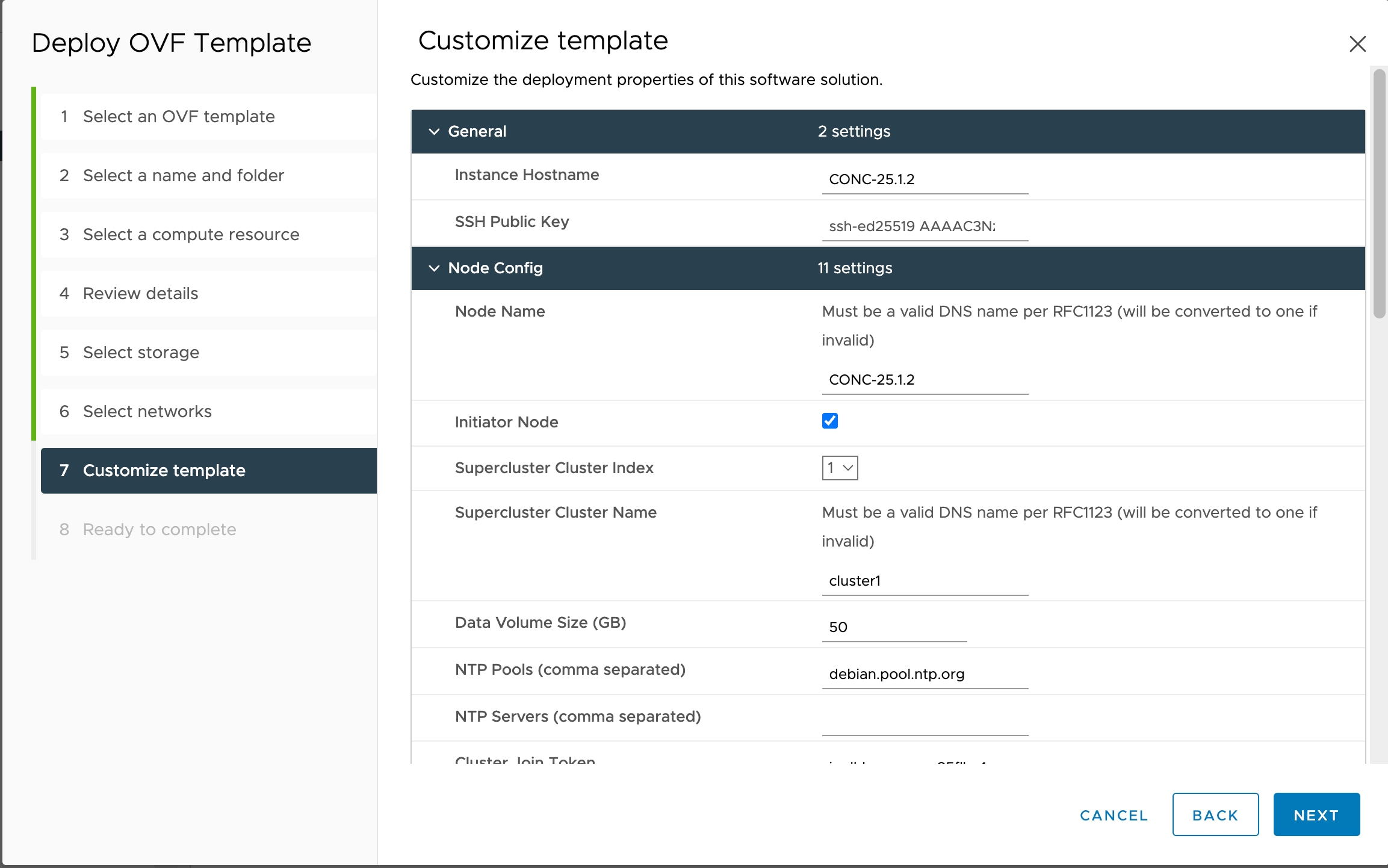
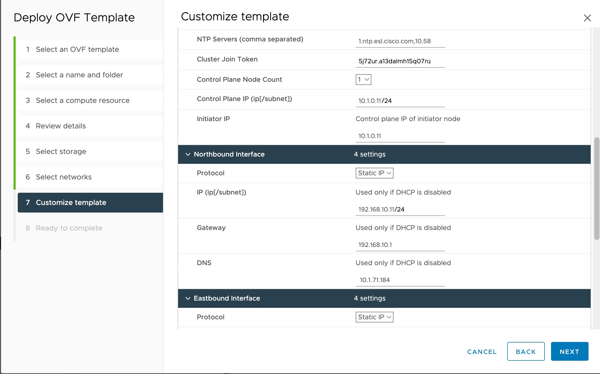
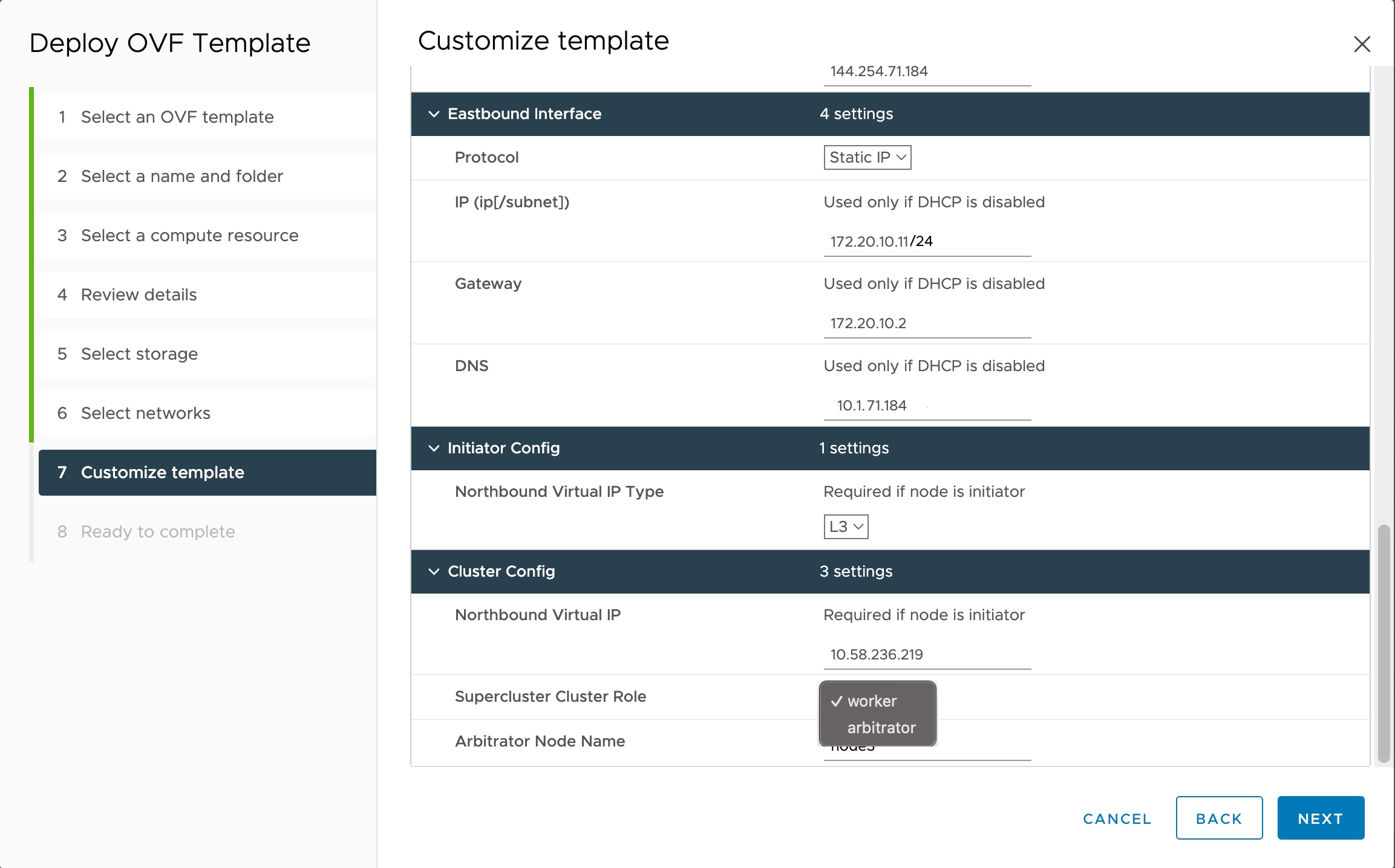
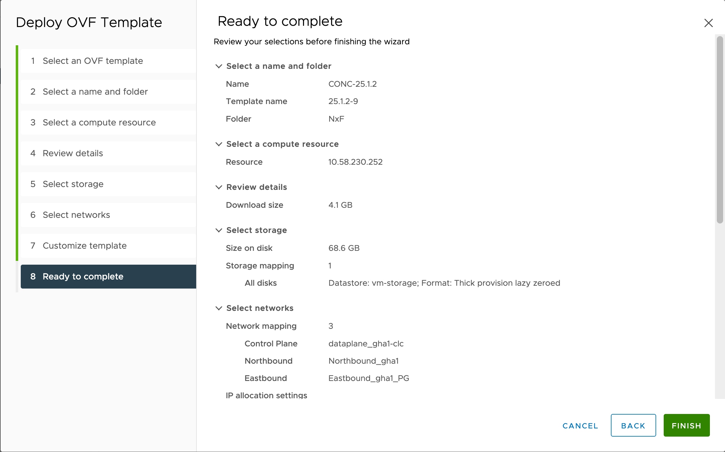
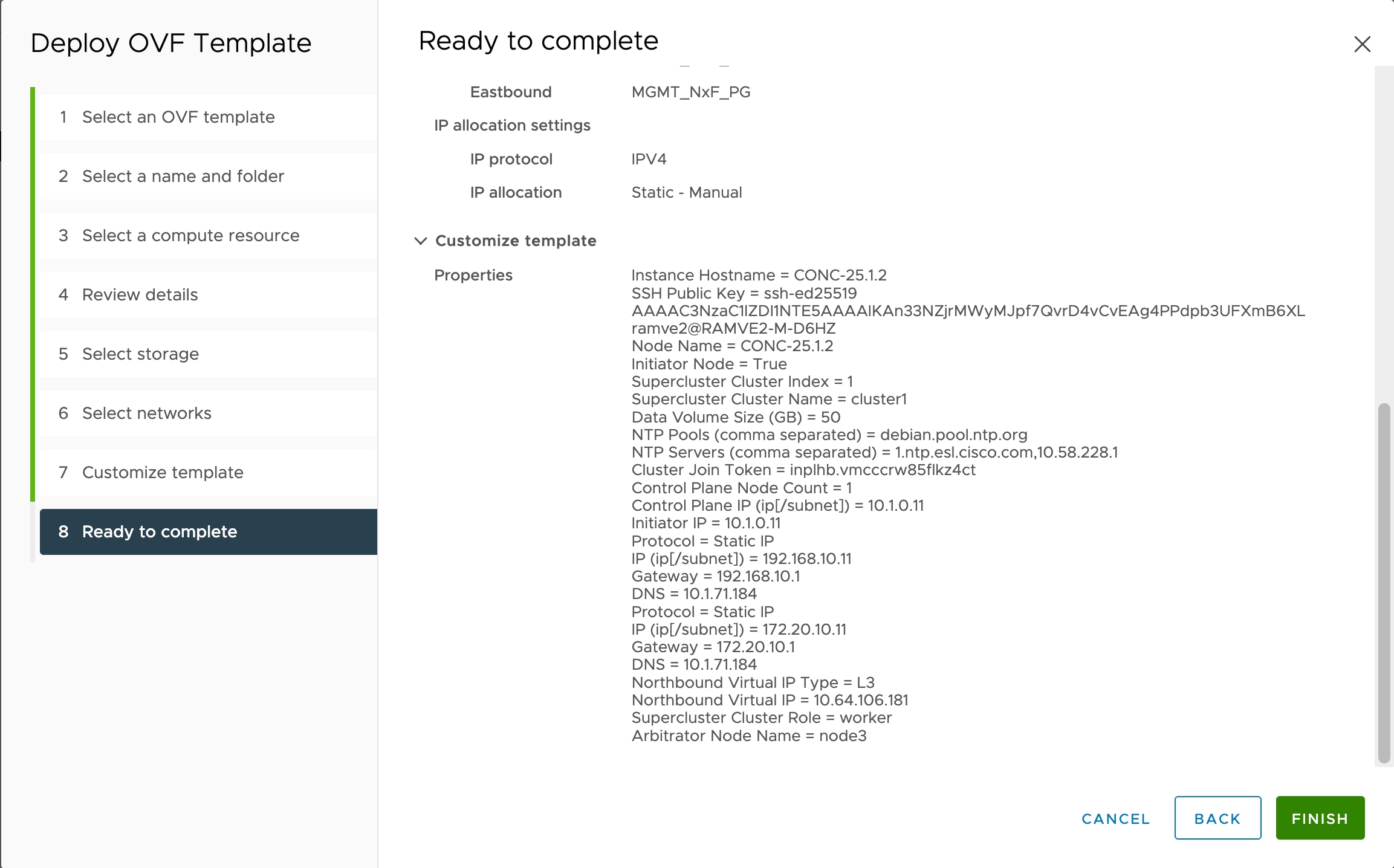
You must have created 3 VMs for geo-redundant deployment of Cisco Optical Network Controller. See Install and Deploy Geo Redundant Cisco Optical Network Controller

Procedure


Step 1

After the VMs are created, try connecting to the VM using the pem key which was generated earlier, see SSH Key Generation. For this, use the private key that is generated along with the public key during customizing the public key options.

Step 2

Log in to each VM using the private key.

# ssh -i <private-key_file> nxf@<node_ip>

Note

 
  • If you are prompted for a password, there might be a problem with the key. If your SSH key has a passphrase, the system prompts you for the passphrase. If you are prompted for a password even after entering your SSH key passphrase, your PEM key might be wrong or corrupted.

  • If the command times out, check your network settings and make sure the node is reachable.

  • After the nodes are deployed, the deployment of OVA progress can be checked in the Tasks console of vSphere Client. After Successful deployment, Cisco Optical Network Controller takes around 20 minutes to boot.

  • The default user ID is admin. Use the sedo security user set admin --password command to set the password.

Step 3

If peer nodes Eastbound IPs are in different subnets, you must create static routes between the nodes for the eastbound traffic flow among the nodes. From each node, create routes to each of the two other nodes.

  1. Navigate to the configuration directory.

    cd /etc/systemd/network/
  2. Identify the Network Configuration File: Find the file associated with the eastbound interface ens256. The filename must be similar to 10-cloud-init-ens256.network.

  3. Open the configuration file using a text editor like nano or vim with administrative privileges:

  4. Update the [Route] Section: Modify the [Route] section by adding the static routes using the following template. Ensure you replace placeholders with actual IP addresses and gateway information as necessary.

    [Match]
    Name=ens256
    
    [Network]
    DHCP=no
    DNS=<dns-server-ip>
    
    [Address]
    Address=<cluster1-eastbound-ip>/<subnet-mask>
    
    [Route]
    Destination=<eastbound-subnet-of-cluster2>/<subnet-mask>
    Gateway=<gateway-ip>
    
    [Route]
    Destination=<eastbound-subnet-of-cluster3>/<subnet-mask>
    Gateway=<gateway-ip>
  5. After editing, save the file and exit the text editor.

    Example:

    Here is a sample file.
    #Example:
    [Match]
    Name=ens256
    
    [Network]
    DHCP=no
    DNS=10.10.128.236
    
    [Address]
    Address=172.10.10.11/24
    
    [Route]
    Destination=172.10.20.0/24
    Gateway=172.30.10.2
    
    [Route]
    Destination=172.10.30.0/24
    Gateway=172.30.10.2

    Note

     
    • Ensure that the Name in the [Match] section corresponds to the correct network interface.

    • Verify that the DNS and Gateway IPs are correctly assigned as per your network requirements.

  6. Use ping to verify connectivity between the nodes.

Step 4

Restart the systemd-networkd service to apply the changes.

Example:

sudo systemctl restart systemd-networkd
You have created routes for communication. Verify that the routes have been created using the ip route command.

Step 5

Configure BGP for virtual IP route advertisement.

  1. Initialize BGP on each node.

    sedo ha bgp init <CURRENT_NODE_NAME> <CURRENT_NODE_NORTHBOUND_IP> <CURRENT_NODE_AS> --nexthop <CURRENT_NODE_NORTHBOUND_IP>
  2. Add a BGP router to each node.

    sedo ha bgp router add <CURRENT_NODE_NAME> <BGP_ROUTER_IP> <BGP_ROUTER_AS> <BGP_PASSWORD> --enable-gtsm

    Note


    Collect the BGP router IP, Router autonomous system number, and the BGP password from your network admin. The BGP password must match the neighbor configuration on the router.

Step 6

Retrieve Cluster ID: On each node, run the following command to retrieve the Cluster ID.:

sedo supercluster status

Example:

sedo supercluster status
#Sample Output
β”Œβ”€β”€β”€β”€β”€β”€β”€β”€β”€β”€β”€β”€β”€β”€β”€β”€β”€β”€β”€β”€β”€β”€β”€β”€β”€β”€β”€β”€β”€β”€β”€β”€β”€β”€β”€β”€β”€β”€β”€β”€β”€β”€β”€β”€β”€β”€β”€β”€β”€β”€β”€β”€β”€β”€β”€β”€β”€β”€β”€β”€β”
β”‚ Supercluster Status                                        β”‚
β”œβ”€β”€β”€β”€β”€β”€β”€β”€β”€β”€β”€β”€β”€β”€β”¬β”€β”€β”€β”€β”€β”€β”€β”€β”€β”€β”€β”€β”€β”€β”€β”€β”€β”€β”€β”€β”€β”€β”€β”€β”€β”€β”€β”€β”€β”€β”€β”€β”€β”€β”€β”€β”€β”€β”€β”€β”€β”€β”€β”€β”€β”€
β”‚ Cluster ID   β”‚ vk0uFBSwM1vX4_mC1BAabDxAKXYUTv1KH5dcCDawZw4 β”‚
β”‚ Cluster Name β”‚ cluster1                                   β”‚
β”‚ Cluster Role β”‚ worker                                      β”‚
β”‚ Peers        β”‚ <No Peers>                                  β”‚
β”‚ Initialized  β”‚ No                                          β”‚
β””β”€β”€β”€β”€β”€β”€β”€β”€β”€β”€β”€β”€β”€β”€β”΄β”€β”€β”€β”€β”€β”€β”€β”€β”€β”€β”€β”€β”€β”€β”€β”€β”€β”€β”€β”€β”€β”€β”€β”€β”€β”€β”€β”€β”€β”€β”€β”€β”€β”€β”€β”€β”€β”€β”€β”€β”€β”€β”€β”€β”€β”˜

Note


The cluster ID for each node is required in the following steps.

Step 7

Connect cluster1 to cluster2.

  1. On cluster1, initiate the supercluster connection by running the following command.

    sudo sedo supercluster wait-for -b <cluster1_node_eastboundIP>:10443 <cluster2_node_CLUSTER_ID>

    Example:

    #Sample Output
    sudo sedo supercluster wait-for -b 172.20.2.89:10443 uUD21AaV4cQ8CzZQf0E0YrGmALi0vHASpZI07YzcsQ
    Listening for join requests on 172.20.2.89:10443...
    Please run the following on peer node:
    $ sudo /usr/bin/sedo supercluster join Lh9Gv3FwSUsx7Gu_7EJoIMe4r5YE6ApyHqOEt83fko https://172.20.2.89:10443/join/g4jKVulJo74ptz82lMvngQ
    
  2. On the Cluster2, execute the command that is generated from Cluster1 to join the supercluster.

    Example:

    sudo /usr/bin/sedo supercluster join Lh9Gv3FwSUsx7Gu_7EJoIMe4r5YE6ApyHqOEt83fko https://172.20.2.89:10443/join/g4jKVulJo74ptz82lMvngQ

Step 8

Connect cluster1 to cluster3.

  1. On cluster1, initiate the supercluster connection by running the following command.

    sudo sedo supercluster wait-for -b <cluster1_node_eastboundIP>:10443 <cluster3_node_CLUSTER_ID>
  2. On the Cluster3, execute the command that is generated from Cluster1 to join the supercluster.

Step 9

Connect cluster2 to cluster3.

  1. On cluster2, initiate the supercluster connection by running the following command.

    sudo sedo supercluster wait-for -b <cluster2_node_eastboundIP>:10443 <cluster3_node_CLUSTER_ID>
  2. On the Cluster3, execute the command that is generated from Cluster2 to join the supercluster.

Step 10

Check Cluster Connectivity: After all clusters are joined, verify connectivity using the following command:

sudo sedo supercluster connectivity

Note


Wait till all connections are successful. It typically takes about 5 minutes for the clusters to establish connectivity between each other.

Example:

sudo sedo supercluster connectivity

β”Œβ”€β”€β”€β”€β”€β”€β”€β”€β”€β”€β”€β”€β”€β”€β”€β”€β”€β”€β”€β”€β”€β”€β”€β”€β”€β”€β”€β”€β”€β”€β”€β”€β”€β”€β”€β”€β”€β”€β”€β”€β”€β”€β”€β”€β”€β”€β”€β”€β”€β”€β”€β”€β”€β”€β”€β”€β”€β”€β”€β”€β”€β”€β”€β”€β”
β”‚ Supercluster Connectivity                                      β”‚
β”œβ”€β”€β”€β”€β”€β”€β”€β”€β”€β”€β”€β”€β”€β”€β”€β”€β”€β”€β”€β”€β”€β”€β”€β”¬β”€β”€β”€β”€β”€β”€β”€β”€β”€β”€β”€β”€β”€β”€β”€β”€β”€β”€β”€β”€β”€β”€β”€β”¬β”€β”€β”€β”€β”€β”€β”¬β”€β”€β”€β”€β”€β”€β”€β”€β”€β”€
β”‚ FROM                  β”‚ TO                    β”‚ RTT  β”‚ RESULT  β”‚
β”œβ”€β”€β”€β”€β”€β”€β”€β”€β”€β”€β”€β”€β”€β”€β”€β”€β”€β”€β”€β”€β”€β”€β”€β”Όβ”€β”€β”€β”€β”€β”€β”€β”€β”€β”€β”€β”€β”€β”€β”€β”€β”€β”€β”€β”€β”€β”€β”€β”Όβ”€β”€β”€β”€β”€β”€β”Όβ”€β”€β”€β”€β”€β”€β”€β”€β”€β”€
β”‚ cluster2/controller-0 β”‚ cluster1/controller-0 β”‚ 14ms β”‚ Success β”‚
β”‚ cluster2/controller-0 β”‚ cluster3/controller-0 β”‚ 15ms β”‚ Success β”‚
β”‚ cluster1/controller-0 β”‚ cluster3/controller-0 β”‚ 12ms β”‚ Success β”‚
β”‚ cluster1/controller-0 β”‚ cluster2/controller-0 β”‚ 12ms β”‚ Success β”‚
β”‚ cluster3/controller-0 β”‚ cluster2/controller-0 β”‚ 13ms β”‚ Success β”‚
β”‚ cluster3/controller-0 β”‚ cluster1/controller-0 β”‚ 13ms β”‚ Success β”‚
β””β”€β”€β”€β”€β”€β”€β”€β”€β”€β”€β”€β”€β”€β”€β”€β”€β”€β”€β”€β”€β”€β”€β”€β”΄β”€β”€β”€β”€β”€β”€β”€β”€β”€β”€β”€β”€β”€β”€β”€β”€β”€β”€β”€β”€β”€β”€β”€β”΄β”€β”€β”€β”€β”€β”€β”΄β”€β”€β”€β”€β”€β”€β”€β”€β”€β”˜ 

Step 11

Start the Super-Cluster: Once connectivity is verified, start the supercluster using the following command:

sudo sedo supercluster start

Note


The node on which you execute this comand becomes the active node and the other worker node becomes the standby node.

Example:

sudo sedo supercluster start

Checking Supercluster connectivity...Passed
Initiating Supercluster...Done 

Step 12

Verify Super-Cluster Status: Check the status of the supercluster to ensure that all nodes are active and properly connected using the following command:

sedo supercluster status

Example:

sedo supercluster status
β”Œβ”€β”€β”€β”€β”€β”€β”€β”€β”€β”€β”€β”€β”€β”€β”€β”€β”€β”€β”€β”€β”€β”€β”€β”€β”€β”€β”€β”€β”€β”€β”€β”€β”€β”€β”€β”€β”€β”€β”€β”€β”€β”€β”€β”€β”€β”€β”€β”€β”€β”€β”€β”€β”€β”€β”€β”€β”€β”€β”€β”€β”€β”€β”€β”€β”€β”€β”€β”€β”€β”€β”€β”€β”€β”€β”€β”€β”€β”€β”€β”€β”€β”€β”€β”€β”€β”€β”
β”‚ Supercluster Status                                                                  β”‚
β”œβ”€β”€β”€β”€β”€β”€β”€β”€β”€β”€β”€β”€β”€β”€β”€β”€β”€β”€β”¬β”€β”€β”€β”€β”€β”€β”€β”€β”€β”€β”€β”€β”€β”€β”€β”€β”€β”€β”€β”€β”€β”€β”€β”€β”€β”€β”€β”€β”€β”€β”€β”€β”€β”€β”€β”€β”€β”€β”€β”€β”€β”€β”€β”€β”€β”€β”€β”€β”€β”€β”€β”€β”€β”€β”€β”€β”€β”€β”€β”€β”€β”€β”€β”€β”€β”€β”€β”€
β”‚ Cluster ID       β”‚ QgQV2uXgP1udqshlIssyTwf3LZzEyRh6I3z5MH8almA                       β”‚
β”‚ Cluster Name     β”‚ cluster1                                                          β”‚
β”‚ Cluster Role     β”‚ worker                                                            β”‚
β”‚ Peers            β”‚ cluster2 (worker, jaWeN9BdXUUTxvofwt6Hukt6OQXIUaqo4NxN6zHYDc)     β”‚
β”‚                  β”‚ cluster3 (arbitrator, SUCrwqQjXToG5GKBwckcg_CtzgHstQigaEM1X0988E) β”‚
β”‚ Mode             β”‚ Running                                                           β”‚
β”‚ Current Active   β”‚ cluster1                                                          β”‚
β”‚ Previous Active  β”‚                                                                   β”‚
β”‚ Standby Clusters β”‚ cluster2                                                          β”‚
β”‚ Last Switchover  β”‚                                                                   β”‚
β”‚ Last Failover    β”‚                                                                   β”‚
β”‚ Last Seen        β”‚ controller-0.cluster2: 2025-03-19 11:16:57.051 +0000 UTC          β”‚
β”‚                  β”‚ controller-0.cluster3: 2025-03-19 11:16:57.047 +0000 UTC          β”‚
β”‚                  β”‚ controller-0.cluster1: 2025-03-19 11:16:57.051 +0000 UTC          β”‚
β”‚ Last Peer Error  β”‚                                                                   β”‚
β”‚ Server Error     β”‚                                                                   β”‚
β”‚ DB Replication   β”‚ streaming                                                         β”‚
β”‚ DB Lag           β”‚ 0 bytes                                                           β”‚
β””β”€β”€β”€β”€β”€β”€β”€β”€β”€β”€β”€β”€β”€β”€β”€β”€β”€β”€β”΄β”€β”€β”€β”€β”€β”€β”€β”€β”€β”€β”€β”€β”€β”€β”€β”€β”€β”€β”€β”€β”€β”€β”€β”€β”€β”€β”€β”€β”€β”€β”€β”€β”€β”€β”€β”€β”€β”€β”€β”€β”€β”€β”€β”€β”€β”€β”€β”€β”€β”€β”€β”€β”€β”€β”€β”€β”€β”€β”€β”€β”€β”€β”€β”€β”€β”€β”€β”˜
 

This sample output shows the output of the command on the standby node. The output shows the current active and standby clusters. When DB replication is streaming, and DB Lag is 0 bytes, the Geo-redundant Deployment is up and running.

Step 13

Use the sedo system status command to check the status of all the pods.

sedo system status
β”Œβ”€β”€β”€β”€β”€β”€β”€β”€β”€β”€β”€β”€β”€β”€β”€β”€β”€β”€β”€β”€β”€β”€β”€β”€β”€β”€β”€β”€β”€β”€β”€β”€β”€β”€β”€β”€β”€β”€β”€β”€β”€β”€β”€β”€β”€β”€β”€β”€β”€β”€β”€β”€β”€β”€β”€β”€β”€β”€β”€β”€β”€β”€β”€β”€β”€β”€β”€β”€β”€β”€β”€β”€β”€β”€β”€β”€β”€β”€β”€β”€β”€β”€β”€β”
β”‚ System Status (Fri, 20 Sep 2024 08:21:27 UTC)                                     β”‚
β”œβ”€β”€β”€β”€β”€β”€β”€β”€β”¬β”€β”€β”€β”€β”€β”€β”€β”€β”€β”€β”€β”€β”€β”€β”€β”€β”€β”€β”€β”€β”€β”€β”€β”€β”€β”€β”€β”€β”€β”€β”¬β”€β”€β”€β”€β”€β”€β”€β”¬β”€β”€β”€β”€β”€β”€β”€β”€β”€β”¬β”€β”€β”€β”€β”€β”€β”€β”€β”€β”€β”¬β”€β”€β”€β”€β”€β”€β”€β”€β”€β”€β”€β”€β”€β”€β”€
β”‚ OWNER  β”‚ NAME                         β”‚ NODE  β”‚ STATUS  β”‚ RESTARTS β”‚ STARTED      β”‚
β”œβ”€β”€β”€β”€β”€β”€β”€β”€β”Όβ”€β”€β”€β”€β”€β”€β”€β”€β”€β”€β”€β”€β”€β”€β”€β”€β”€β”€β”€β”€β”€β”€β”€β”€β”€β”€β”€β”€β”€β”€β”Όβ”€β”€β”€β”€β”€β”€β”€β”Όβ”€β”€β”€β”€β”€β”€β”€β”€β”€β”Όβ”€β”€β”€β”€β”€β”€β”€β”€β”€β”€β”Όβ”€β”€β”€β”€β”€β”€β”€β”€β”€β”€β”€β”€β”€β”€β”€
β”‚ onc    β”‚ monitoring                   β”‚ node1 β”‚ Running β”‚ 0        β”‚ 3 hours ago  β”‚
β”‚ onc    β”‚ onc-alarm-service            β”‚ node1 β”‚ Running β”‚ 0        β”‚ 3 hours ago  β”‚
β”‚ onc    β”‚ onc-apps-ui-service          β”‚ node1 β”‚ Running β”‚ 0        β”‚ 3 hours ago  β”‚
β”‚ onc    β”‚ onc-circuit-service          β”‚ node1 β”‚ Running β”‚ 0        β”‚ 3 hours ago  β”‚
β”‚ onc    β”‚ onc-collector-service        β”‚ node1 β”‚ Running β”‚ 0        β”‚ 3 hours ago  β”‚
β”‚ onc    β”‚ onc-config-service           β”‚ node1 β”‚ Running β”‚ 0        β”‚ 3 hours ago  β”‚
β”‚ onc    β”‚ onc-devicemanager-service    β”‚ node1 β”‚ Running β”‚ 0        β”‚ 3 hours ago  β”‚
β”‚ onc    β”‚ onc-inventory-service        β”‚ node1 β”‚ Running β”‚ 0        β”‚ 3 hours ago  β”‚
β”‚ onc    β”‚ onc-nbi-service              β”‚ node1 β”‚ Running β”‚ 0        β”‚ 3 hours ago  β”‚
β”‚ onc    β”‚ onc-netconfcollector-service β”‚ node1 β”‚ Running β”‚ 0        β”‚ 3 hours ago  β”‚
β”‚ onc    β”‚ onc-osapi-gw-service         β”‚ node1 β”‚ Running β”‚ 0        β”‚ 3 hours ago  β”‚
β”‚ onc    β”‚ onc-pce-service              β”‚ node1 β”‚ Running β”‚ 0        β”‚ 3 hours ago  β”‚
β”‚ onc    β”‚ onc-pm-service               β”‚ node1 β”‚ Running β”‚ 0        β”‚ 3 hours ago  β”‚
β”‚ onc    β”‚ onc-pmcollector-service      β”‚ node1 β”‚ Running β”‚ 0        β”‚ 3 hours ago  β”‚
β”‚ onc    β”‚ onc-topology-service         β”‚ node1 β”‚ Running β”‚ 0        β”‚ 3 hours ago  β”‚
β”‚ onc    β”‚ onc-torch-service            β”‚ node1 β”‚ Running β”‚ 0        β”‚ 3 hours ago  β”‚
β”‚ system β”‚ authenticator                β”‚ node1 β”‚ Running β”‚ 0        β”‚ 12 hours ago β”‚
β”‚ system β”‚ controller                   β”‚ node1 β”‚ Running β”‚ 0        β”‚ 12 hours ago β”‚
β”‚ system β”‚ flannel                      β”‚ node1 β”‚ Running β”‚ 0        β”‚ 12 hours ago β”‚
β”‚ system β”‚ ingress-proxy                β”‚ node1 β”‚ Running β”‚ 0        β”‚ 12 hours ago β”‚
β”‚ system β”‚ kafka                        β”‚ node1 β”‚ Running β”‚ 0        β”‚ 12 hours ago β”‚
β”‚ system β”‚ loki                         β”‚ node1 β”‚ Running β”‚ 0        β”‚ 12 hours ago β”‚
β”‚ system β”‚ metrics                      β”‚ node1 β”‚ Running β”‚ 0        β”‚ 12 hours ago β”‚
β”‚ system β”‚ minio                        β”‚ node1 β”‚ Running β”‚ 0        β”‚ 12 hours ago β”‚
β”‚ system β”‚ postgres                     β”‚ node1 β”‚ Running β”‚ 0        β”‚ 12 hours ago β”‚
β”‚ system β”‚ promtail-cltmk               β”‚ node1 β”‚ Running β”‚ 0        β”‚ 12 hours ago β”‚
β”‚ system β”‚ vip-add                      β”‚ node1 β”‚ Running β”‚ 0        β”‚ 12 hours ago β”‚
β””β”€β”€β”€β”€β”€β”€β”€β”€β”΄β”€β”€β”€β”€β”€β”€β”€β”€β”€β”€β”€β”€β”€β”€β”€β”€β”€β”€β”€β”€β”€β”€β”€β”€β”€β”€β”€β”€β”€β”€β”΄β”€β”€β”€β”€β”€β”€β”€β”΄β”€β”€β”€β”€β”€β”€β”€β”€β”€β”΄β”€β”€β”€β”€β”€β”€β”€β”€β”€β”€β”΄β”€β”€β”€β”€β”€β”€β”€β”€β”€β”€β”€β”€β”€β”€β”˜

Note

 
  • The different pods along with their statuses are displayed in the different terminal sessions for each node.

  • The status of all the services must be Running.

Step 14

You can check the current version using the sedo version command.

sedo version
β”Œβ”€β”€β”€β”€β”€β”€β”€β”€β”€β”€β”€β”€β”€β”€β”€β”€β”€β”€β”€β”€β”€β”€β”€β”€β”€β”€β”€β”€β”€β”€β”€β”€β”€β”€β”€β”€β”€β”€β”€β”€β”€β”€β”€β”€β”€β”€β”€β”€β”€β”€β”€β”€β”€β”€β”€β”€β”€β”€β”€β”€β”€β”€β”€β”€β”€β”€β”€β”€β”€β”€β”€β”€β”€β”€β”€β”€β”€β”€β”€β”€β”€β”€β”€β”€β”€β”€β”€β”€β”€β”€β”
β”‚Installer: 24.3.2                                                    β”‚
β”œβ”€β”€β”€β”€β”€β”€β”€β”€β”€β”€β”€β”€β”€β”€β”¬β”€β”€β”€β”€β”€β”€β”€β”€β”€β”€β”€β”€β”€β”€β”€β”€β”€β”€β”€β”€β”€β”€β”€β”€β”€β”€β”€β”€β”€β”€β”€β”€β”€β”€β”€β”€β”€β”€β”€β”€β”€β”€β”€β”€β”€β”€β”€β”€β”€β”€β”€β”€β”€β”€β”€β”€β”€β”€β”¬β”€β”€β”€β”€β”€β”€β”€β”€β”€β”€β”€β”€β”€β”€β”€β”€β”€
β”‚ NODE NAME    β”‚ OS VERSION                                               β”‚ KERNEL VERSION β”‚
β”œβ”€β”€β”€β”€β”€β”€β”€β”€β”€β”€β”€β”€β”€β”€β”Όβ”€β”€β”€β”€β”€β”€β”€β”€β”€β”€β”€β”€β”€β”€β”€β”€β”€β”€β”€β”€β”€β”€β”€β”€β”€β”€β”€β”€β”€β”€β”€β”€β”€β”€β”€β”€β”€β”€β”€β”€β”€β”€β”€β”€β”€β”€β”€β”€β”€β”€β”€β”€β”€β”€β”€β”€β”€β”€β”Όβ”€β”€β”€β”€β”€β”€β”€β”€β”€β”€β”€β”€β”€β”€β”€β”€β”€
β”‚ node1-c1-sa1 β”‚ NxFOS 3.2-555 (93358ad257a6cf1e3da439144e3d2e8343b53008) β”‚ 6.1.0-31-amd64 β”‚
β””β”€β”€β”€β”€β”€β”€β”€β”€β”€β”€β”€β”€β”€β”€β”΄β”€β”€β”€β”€β”€β”€β”€β”€β”€β”€β”€β”€β”€β”€β”€β”€β”€β”€β”€β”€β”€β”€β”€β”€β”€β”€β”€β”€β”€β”€β”€β”€β”€β”€β”€β”€β”€β”€β”€β”€β”€β”€β”€β”€β”€β”€β”€β”€β”€β”€β”€β”€β”€β”€β”€β”€β”€β”€β”΄β”€β”€β”€β”€β”€β”€β”€β”€β”€β”€β”€β”€β”€β”€β”€β”€β”˜
β”Œβ”€β”€β”€β”€β”€β”€β”€β”€β”€β”€β”€β”€β”€β”€β”€β”€β”€β”€β”€β”€β”€β”€β”€β”€β”€β”€β”€β”€β”€β”€β”€β”€β”€β”€β”€β”€β”€β”€β”€β”€β”€β”€β”€β”€β”€β”€β”€β”€β”€β”€β”€β”€β”€β”€β”€β”€β”€β”€β”€β”€β”€β”€β”€β”€β”€β”€β”€β”€β”€β”€β”€β”€β”€β”€β”€β”€β”¬β”€β”€β”€β”€β”€β”€β”€β”€β”€β”€β”€β”€β”€β”€β”€β”€β”€β”€β”€β”€β”€β”€β”€β”€β”€β”€β”€β”€β”€β”€β”€β”€β”€β”€β”€β”€β”€β”€β”€β”€β”€β”€β”€β”€β”€β”€β”€β”€β”€β”€β”€β”€β”€β”€β”€β”€β”€β”€β”€β”€β”¬β”€β”€β”€β”€β”€β”€β”€β”€β”€β”€β”€β”€β”€β”€β”
β”‚ IMAGE NAME                                                                 β”‚ VERSION                                                    β”‚ NODES        β”‚
β”œβ”€β”€β”€β”€β”€β”€β”€β”€β”€β”€β”€β”€β”€β”€β”€β”€β”€β”€β”€β”€β”€β”€β”€β”€β”€β”€β”€β”€β”€β”€β”€β”€β”€β”€β”€β”€β”€β”€β”€β”€β”€β”€β”€β”€β”€β”€β”€β”€β”€β”€β”€β”€β”€β”€β”€β”€β”€β”€β”€β”€β”€β”€β”€β”€β”€β”€β”€β”€β”€β”€β”€β”€β”€β”€β”€β”€β”Όβ”€β”€β”€β”€β”€β”€β”€β”€β”€β”€β”€β”€β”€β”€β”€β”€β”€β”€β”€β”€β”€β”€β”€β”€β”€β”€β”€β”€β”€β”€β”€β”€β”€β”€β”€β”€β”€β”€β”€β”€β”€β”€β”€β”€β”€β”€β”€β”€β”€β”€β”€β”€β”€β”€β”€β”€β”€β”€β”€β”€β”Όβ”€β”€β”€β”€β”€β”€β”€β”€β”€β”€β”€β”€β”€β”€β”€
...
β””β”€β”€β”€β”€β”€β”€β”€β”€β”€β”€β”€β”€β”€β”€β”€β”€β”€β”€β”€β”€β”€β”€β”€β”€β”€β”€β”€β”€β”€β”€β”€β”€β”€β”€β”€β”€β”€β”€β”€β”€β”€β”€β”€β”€β”€β”€β”€β”€β”€β”€β”€β”€β”€β”€β”€β”€β”€β”€β”€β”€β”€β”€β”€β”€β”€β”€β”€β”€β”€β”€β”€β”€β”€β”΄β”€β”€β”€β”€β”€β”€β”€β”€β”€β”€β”€β”€β”€β”€β”€β”€β”€β”€β”€β”€β”€β”€β”€β”€β”€β”€β”€β”€β”€β”€β”€β”€β”€β”€β”€β”€β”€β”€β”€β”€β”€β”€β”€β”€β”€β”€β”€β”€β”€β”€β”€β”€β”€β”€β”€β”€β”€β”€β”€β”€β”΄β”€β”€β”€β”€β”€β”€β”€β”€β”€β”€β”€β”€β”€β”€β”€β”€β”€β”€β”˜

What to do next

Set Up Web UI Access to Cisco Optical Network Controller

Set Up Web UI Access to Cisco Optical Network Controller

Procedure


Step 1

Set the initial UI password for the admin user. Execute the following command.

Example:

sedo security user set admin --password

Note


The password policy for the system includes both configurable settings and nonconfigurable hard requirements to ensure security.

Password Requirements

  • The password must contain at least:

    • 1 uppercase letter

    • 1 lowercase letter

    • 1 number

    • 1 special character

  • Must have a minimum length of 8 characters.

Configurable Requirements

You can change the password policy settings using the sedo security password-policy set command. Specify the desired parameters to adjust the configuration:

sedo security password-policy set --expiration-days <number> --reuse-limit <number> --min-complexity-score <number>
  • expiration-days: Default password expiration used when creating new users, in days (default 180)

  • min-complexity-score: The password strength forced for local users can be enabled or disabled and can be set in scores of 1 to 5 (weak to strong). The password is checked against several dictionaries and common passwords lists, to ensure its complexity according to the selected score.(default 3)

  • reuse-limit: Number of historical passwords that are retained and blocked from reuse when changing password (default 12)

Step 2

To check the default admin user ID, use the command sedo security user list. To change the default password, use the command sedo security user admin set --password on the CLI console of the VM or through the web UI.

Step 3

Use a web browser to access https://<virtual IP>:8443/ to access the Cisco Optical Network Controller Web UI. Use the admin user id and the password that you set to log in to Cisco Optical Network Controller.

Note


Access the web UI only after all the onc services are running. Use the sedo system status command to verify that all services are running.


Perform a Switchover in a Geo Redundant Cisco Optical Network Controller Deployment

To switch the active and standby clusters, perform the following steps.

Before you begin

You must have a Geo Redundant Cisco Optical Network Controller Deployment.

Run the sedo supercluster status command to view the supercluster status.

sedo supercluster status
β”Œβ”€β”€β”€β”€β”€β”€β”€β”€β”€β”€β”€β”€β”€β”€β”€β”€β”€β”€β”€β”€β”€β”€β”€β”€β”€β”€β”€β”€β”€β”€β”€β”€β”€β”€β”€β”€β”€β”€β”€β”€β”€β”€β”€β”€β”€β”€β”€β”€β”€β”€β”€β”€β”€β”€β”€β”€β”€β”€β”€β”€β”€β”€β”€β”€β”€β”€β”€β”€β”€β”€β”€β”€β”€β”€β”€β”€β”€β”€β”€β”€β”€β”€β”€β”€β”€β”€β”
β”‚ Supercluster Status                                                                  β”‚
β”œβ”€β”€β”€β”€β”€β”€β”€β”€β”€β”€β”€β”€β”€β”€β”€β”€β”€β”€β”¬β”€β”€β”€β”€β”€β”€β”€β”€β”€β”€β”€β”€β”€β”€β”€β”€β”€β”€β”€β”€β”€β”€β”€β”€β”€β”€β”€β”€β”€β”€β”€β”€β”€β”€β”€β”€β”€β”€β”€β”€β”€β”€β”€β”€β”€β”€β”€β”€β”€β”€β”€β”€β”€β”€β”€β”€β”€β”€β”€β”€β”€β”€β”€β”€β”€β”€β”€β”€
β”‚ Cluster ID       β”‚ QgQV2uXgP1udqshlIssyTwf3LZzEyRh6I3z5MH8almA                       β”‚
β”‚ Cluster Name     β”‚ cluster1                                                          β”‚
β”‚ Cluster Role     β”‚ worker                                                            β”‚
β”‚ Peers            β”‚ cluster2 (worker, jaWeN9BdXUUTxvofwt6Hukt6OQXIUaqo4NxN6zHYDc)     β”‚
β”‚                  β”‚ cluster3 (arbitrator, SUCrwqQjXToG5GKBwckcg_CtzgHstQigaEM1X0988E) β”‚
β”‚ Mode             β”‚ Running                                                           β”‚
β”‚ Current Active   β”‚ cluster1                                                          β”‚
β”‚ Previous Active  β”‚                                                                   β”‚
β”‚ Standby Clusters β”‚ cluster2                                                          β”‚
β”‚ Last Switchover  β”‚                                                                   β”‚
β”‚ Last Failover    β”‚                                                                   β”‚
β”‚ Last Seen        β”‚ controller-0.cluster2: 2025-03-19 11:16:57.051 +0000 UTC          β”‚
β”‚                  β”‚ controller-0.cluster3: 2025-03-19 11:16:57.047 +0000 UTC          β”‚
β”‚                  β”‚ controller-0.cluster1: 2025-03-19 11:16:57.051 +0000 UTC          β”‚
β”‚ Last Peer Error  β”‚                                                                   β”‚
β”‚ Server Error     β”‚                                                                   β”‚
β”‚ DB Replication   β”‚ streaming                                                         β”‚
β”‚ DB Lag           β”‚ 0 bytes                                                           β”‚
β””β”€β”€β”€β”€β”€β”€β”€β”€β”€β”€β”€β”€β”€β”€β”€β”€β”€β”€β”΄β”€β”€β”€β”€β”€β”€β”€β”€β”€β”€β”€β”€β”€β”€β”€β”€β”€β”€β”€β”€β”€β”€β”€β”€β”€β”€β”€β”€β”€β”€β”€β”€β”€β”€β”€β”€β”€β”€β”€β”€β”€β”€β”€β”€β”€β”€β”€β”€β”€β”€β”€β”€β”€β”€β”€β”€β”€β”€β”€β”€β”€β”€β”€β”€β”€β”€β”€β”˜

Procedure


Step 1

Execute the sedo supercluster switchover <target-active-cluster-name> and confirm when prompted.

Example:

nxf@node:~$ sudo sedo supercluster switchover cluster2
Are you sure you want to initiate supercluster switchover to cluster "cluster2"? [y/n]y
The switchover takes place and the WebUI displays a message that says Switchover happened. Please refresh the page. The WebUI update takes about 20 seconds.

Step 2

SSH in to the new active node or using the Virtual IP. Run the sedo supercluster status command to view the supercluster status.

sedo supercluster status
β”Œβ”€β”€β”€β”€β”€β”€β”€β”€β”€β”€β”€β”€β”€β”€β”€β”€β”€β”€β”€β”€β”€β”€β”€β”€β”€β”€β”€β”€β”€β”€β”€β”€β”€β”€β”€β”€β”€β”€β”€β”€β”€β”€β”€β”€β”€β”€β”€β”€β”€β”€β”€β”€β”€β”€β”€β”€β”€β”€β”€β”€β”€β”€β”€β”€β”€β”€β”€β”€β”€β”€β”€β”€β”€β”€β”€β”€β”€β”€β”€β”€β”€β”€β”€β”€β”€β”€β”
β”‚ Supercluster Status                                                                  β”‚
β”œβ”€β”€β”€β”€β”€β”€β”€β”€β”€β”€β”€β”€β”€β”€β”€β”€β”€β”€β”¬β”€β”€β”€β”€β”€β”€β”€β”€β”€β”€β”€β”€β”€β”€β”€β”€β”€β”€β”€β”€β”€β”€β”€β”€β”€β”€β”€β”€β”€β”€β”€β”€β”€β”€β”€β”€β”€β”€β”€β”€β”€β”€β”€β”€β”€β”€β”€β”€β”€β”€β”€β”€β”€β”€β”€β”€β”€β”€β”€β”€β”€β”€β”€β”€β”€β”€β”€β”€
β”‚ Cluster ID       β”‚ jaWeN9BdXUUTxvofwt6Hukt6OQXIUaqo4NxN6zHYDc                        β”‚
β”‚ Cluster Name     β”‚ cluster2                                                          β”‚
β”‚ Cluster Role     β”‚ worker                                                            β”‚
β”‚ Peers            β”‚ cluster1 (worker, QgQV2uXgP1udqshlIssyTwf3LZzEyRh6I3z5MH8almA)    β”‚
β”‚                  β”‚ cluster3 (arbitrator, SUCrwqQjXToG5GKBwckcg_CtzgHstQigaEM1X0988E) β”‚
β”‚ Mode             β”‚ Running                                                           β”‚
β”‚ Current Active   β”‚ cluster2                                                          β”‚
β”‚ Previous Active  β”‚ cluster1                                                          β”‚
β”‚ Standby Clusters β”‚ cluster1                                                          β”‚
β”‚ Last Switchover  β”‚ 2025-03-19 11:20:49.705 +0000 UTC                                 β”‚
β”‚ Last Failover    β”‚                                                                   β”‚
β”‚ Last Seen        β”‚ controller-0.cluster1: 2025-03-19 11:24:07.056 +0000 UTC          β”‚
β”‚                  β”‚ controller-0.cluster2: 2025-03-19 11:24:07.058 +0000 UTC          β”‚
β”‚                  β”‚ controller-0.cluster3: 2025-03-19 11:24:07.058 +0000 UTC          β”‚
β”‚ Last Peer Error  β”‚                                                                   β”‚
β”‚ Server Error     β”‚                                                                   β”‚
β”‚ DB Replication   β”‚ streaming                                                         β”‚
β”‚ DB Lag           β”‚ 0 bytes                                                           β”‚
β””β”€β”€β”€β”€β”€β”€β”€β”€β”€β”€β”€β”€β”€β”€β”€β”€β”€β”€β”΄β”€β”€β”€β”€β”€β”€β”€β”€β”€β”€β”€β”€β”€β”€β”€β”€β”€β”€β”€β”€β”€β”€β”€β”€β”€β”€β”€β”€β”€β”€β”€β”€β”€β”€β”€β”€β”€β”€β”€β”€β”€β”€β”€β”€β”€β”€β”€β”€β”€β”€β”€β”€β”€β”€β”€β”€β”€β”€β”€β”€β”€β”€β”€β”€β”€β”€β”€β”˜

The DB replication status changes from Disconnected to Streaming as the switchover process progresses. Database replication is complete when the DB Replication status is streaming and DB Lag is 0 bytes.

Note


A switchover alarm is raised by Cisco Optical Network Controller during the switchover process. The alarm is cleared after the switchover. You can see the alarm details under Alarm History in the alarms app.

Step 3

(Optional) Use the raft API to get the supercluster status.

Example:

nxf@node:~$ kubectl exec -it onc-devicemanager-service-0 -- curl -X GET http://controller.nxf-system.svc.cluster.local/api/v1/raft/status

The API response gives you the information from the sedo supercluster status command.

Restriction

 
  • Do not perform a switchover until the DB replication status is Streaming and DB Lag is 0 bytes after the previous switchover. This typically takes five minutes.

  • If you perform a switchover while a delete operation was in progress, you must repeat the deleted operation on the new active after the switchover. This restriction applies to node and circuit delete operations.

  • If the active cluster goes down for some reason, a failover takes place. The web UI goes down for up to a minute during a failover. The switchover alarm is raised if a failover occurs.


Upgrade a Standalone Deployment of Cisco Optical Network Controller to a Geo-Redundant Deployment

Cisco Optical Network Controller supports upgrades to 25.1.2 from previous releases. This table lists the upgrade paths you must follow.

Table 3. Upgrade paths
Current version Upgrade Path to 25.1.2
24.3.2 24.3.2 > 25.1.2
25.1.1 25.1.1 > 25.1.2
24.3.1 24.3.1 > 24.3.2 > 25.1.2
24.3.1 > 25.1.1 > 25.1.2

The following sections provide instructions for upgrading a standalone deployment of Cisco Optical Network Controller from Release 25.1.1 to 25.1.2 and configuring the necessary networks to ensure seamless communication between nodes in a geo-redundant supercluster.


Restriction


  • Cisco Optical Network Controller does not support downgrading to an older release. To go back to an older version, take a database backup using the SWIMU application and install the older version using the ova file for the release. After installation, restore the database.

  • You can only revert to a previous version if you have created a copy of the target Cisco Optical Network Controller database before upgrading Cisco Optical Network Controller, as described in Backup and Restore Database.


Before you begin

  • Backup Creation: Ensure that a full system backup is created. See Backup and Restore Database or use the sedo backup create full command and export the backup for recovery if needed. Use this backup to revert to the older version if your upgrade fails.

    Example:

    root@conc-1:~# sedo backup  create full 
    Creating backup, this may take a while...
    Done creating backup
    
    
    root@conc-1:~# sedo backup  list
    β”Œβ”€β”€β”€β”€β”€β”€β”€β”€β”€β”€β”€β”€β”€β”€β”€β”€β”€β”€β”€β”€β”€β”€β”€β”€β”€β”€β”€β”€β”€β”€β”€β”¬β”€β”€β”€β”€β”€β”€β”€β”€β”€β”€β”€β”€β”€β”€β”€β”€β”€β”€β”€β”€β”€β”€β”€β”€β”€β”€β”€β”€β”€β”€β”€β”€β”€β”€β”€β”€β”€β”€β”€β”€β”€β”¬β”€β”€β”€β”€β”€β”€β”€β”€β”€β”€β”€β”€β”€β”€β”€β”€β”€β”€β”€β”€β”€β”€β”€β”€β”€β”€β”€β”€β”€β”¬β”€β”€β”€β”€β”€β”€β”¬β”€β”€β”€β”€β”€β”€β”€β”€β”€β”€β”€β”€β”¬β”€β”€β”€β”€β”€β”€β”€β”€β”€β”€β”€β”€β”€β”€β”€β”€β”€β”€β”
    β”‚ NAME                          β”‚ TIME                                    β”‚ SIZE                        β”‚ TYPE β”‚ HOSTNAME   β”‚ POSTGRES VERSION β”‚
    β”œβ”€β”€β”€β”€β”€β”€β”€β”€β”€β”€β”€β”€β”€β”€β”€β”€β”€β”€β”€β”€β”€β”€β”€β”€β”€β”€β”€β”€β”€β”€β”€β”Όβ”€β”€β”€β”€β”€β”€β”€β”€β”€β”€β”€β”€β”€β”€β”€β”€β”€β”€β”€β”€β”€β”€β”€β”€β”€β”€β”€β”€β”€β”€β”€β”€β”€β”€β”€β”€β”€β”€β”€β”€β”€β”Όβ”€β”€β”€β”€β”€β”€β”€β”€β”€β”€β”€β”€β”€β”€β”€β”€β”€β”€β”€β”€β”€β”€β”€β”€β”€β”€β”€β”€β”€β”Όβ”€β”€β”€β”€β”€β”€β”Όβ”€β”€β”€β”€β”€β”€β”€β”€β”€β”€β”€β”€β”Όβ”€β”€β”€β”€β”€β”€β”€β”€β”€β”€β”€β”€β”€β”€β”€β”€β”€β”€β”€
    β”‚ base_0000000E000000010000009E β”‚ 2025-03-11 04:11:47.733980894 +0000 UTC β”‚ 87 MB (838 MB Uncompressed) β”‚ full β”‚ postgres-0 β”‚ 150008           β”‚
    β””β”€β”€β”€β”€β”€β”€β”€β”€β”€β”€β”€β”€β”€β”€β”€β”€β”€β”€β”€β”€β”€β”€β”€β”€β”€β”€β”€β”€β”€β”€β”€β”΄β”€β”€β”€β”€β”€β”€β”€β”€β”€β”€β”€β”€β”€β”€β”€β”€β”€β”€β”€β”€β”€β”€β”€β”€β”€β”€β”€β”€β”€β”€β”€β”€β”€β”€β”€β”€β”€β”€β”€β”€β”€β”΄β”€β”€β”€β”€β”€β”€β”€β”€β”€β”€β”€β”€β”€β”€β”€β”€β”€β”€β”€β”€β”€β”€β”€β”€β”€β”€β”€β”€β”€β”΄β”€β”€β”€β”€β”€β”€β”΄β”€β”€β”€β”€β”€β”€β”€β”€β”€β”€β”€β”€β”΄β”€β”€β”€β”€β”€β”€β”€β”€β”€β”€β”€β”€β”€β”€β”€β”€β”€β”€β”˜
    
    
    root@conc-1:~# cd /data
    root@conc-1:/data# sedo backup download base_0000000E000000010000009E
    Downloading Backup       ...  [.....<#>...............] [63.03MB in 9.200973s]
    Finished downloading backup to "/data/nxf-backup-3.2-1741666307.tar.gz"
    
    root@conc-1:/data# scp /data/nxf-backup-3.0-1736872559.tar.gz <remote location>
    
  • Network Configuration: Before installing Cisco Optical Network Controller, three networks must be created.

    • Control Plane Network: The control plane network helps in the internal communication between the deployed VMs within a cluster.

    • VM Network or Northbound Network: The VM network is used for communication between the user and the cluster. It handles all the traffic to and from the VMs running on your ESXi hosts. This network is your public network through which the UI is hosted. Cisco Optical Network Controller uses this network to connect to Cisco Optical Site Manager devices using Netconf/gRPC.

    • Eastbound Network: The Eastbound Network helps in the internal communication between the deployed VMs within a supercluster. The active and standby nodes use this network to sync there databases. The postgres database is replicated across active and standby. MinIO is replicated on the arbitrator also.


      Note


      Bandwidth requirement: The Eastbound network should have a bandwidth of 1 Gbps and a latency less than 100 ms.

      You can configure the Eastbound network to be a flat Layer 2 network or an L2VPN where the Eastbound IPs of all the nodes are in the same subnet. If your Eastbound IPs are in different subnets, you must configure static routing between your nodes for the eastbound network.


  • BGP Router Configuration: Obtain the BGP router IP, Router autonomous system number, and BGP password from network administrators for configuration.

  • VMware Setup: Ensure that the vCenter has the required networks configured and attached correctly. Verify that physical adapters are correctly mapped for Northbound and Eastbound networks.

  • Access and Permissions: Ensure you have the necessary permissions to execute commands and modify network settings on the nodes.

Procedure


Step 1

Log in to the standalone node CLI using the private key.

Example:

ssh -i <private-key_file> nxf@<node_ip>

Step 2

Download or copy the 25.1.2 system pack system-pack-file.tar.gz to the NxF SA system running 25.1.1 and place it in the /tmp directory using curl or scp.

Example:

scp user@remote_server:/path/to/system-pack-file.tar.gz /tmp/
curl -o /tmp/system-pack-file.tar.gz http://example.com/path/to/system-pack-file.tar.gz

Step 3

Upgrade the SA VM from 25.1.1 to 25.1.2 using the sedo system upgrade commands:

Example:

sedo system upgrade upload /tmp/system-pack-file.tar.gz
sedo system upgrade apply
reboot
The system reboots and upgrades. The system takes approximately 30 minutes to complete this.

Step 4

After the system reboots, verify the NxF version and system status. Use the sedo version and sedo system status commands.

Example:

sedo version
β”Œβ”€β”€β”€β”€β”€β”€β”€β”€β”€β”€β”€β”€β”€β”€β”€β”€β”€β”€β”€β”€β”€β”€β”€β”€β”€β”€β”€β”€β”€β”€β”€β”€β”€β”€β”€β”€β”€β”€β”€β”€β”€β”€β”€β”€β”€β”€β”€β”€β”€β”€β”€β”€β”€β”€β”€β”€β”€β”€β”€β”€β”€β”€β”€β”€β”€β”€β”€β”€β”€β”€β”€β”€β”€β”€β”€β”€β”€β”€β”€β”€β”€β”€β”€β”€β”€β”€β”€β”€β”€β”€β”
β”‚ Installer: 24.3.2                                                                        β”‚
β”œβ”€β”€β”€β”€β”€β”€β”€β”€β”€β”€β”€β”€β”€β”€β”¬β”€β”€β”€β”€β”€β”€β”€β”€β”€β”€β”€β”€β”€β”€β”€β”€β”€β”€β”€β”€β”€β”€β”€β”€β”€β”€β”€β”€β”€β”€β”€β”€β”€β”€β”€β”€β”€β”€β”€β”€β”€β”€β”€β”€β”€β”€β”€β”€β”€β”€β”€β”€β”€β”€β”€β”€β”€β”€β”¬β”€β”€β”€β”€β”€β”€β”€β”€β”€β”€β”€β”€β”€β”€β”€β”€β”€
β”‚ NODE NAME    β”‚ OS VERSION                                               β”‚ KERNEL VERSION β”‚
β”œβ”€β”€β”€β”€β”€β”€β”€β”€β”€β”€β”€β”€β”€β”€β”Όβ”€β”€β”€β”€β”€β”€β”€β”€β”€β”€β”€β”€β”€β”€β”€β”€β”€β”€β”€β”€β”€β”€β”€β”€β”€β”€β”€β”€β”€β”€β”€β”€β”€β”€β”€β”€β”€β”€β”€β”€β”€β”€β”€β”€β”€β”€β”€β”€β”€β”€β”€β”€β”€β”€β”€β”€β”€β”€β”Όβ”€β”€β”€β”€β”€β”€β”€β”€β”€β”€β”€β”€β”€β”€β”€β”€β”€
β”‚ node1-c1-sc2 β”‚ NxFOS 3.2-555 (93358ad257a6cf1e3da439144e3d2e8343b53008) β”‚ 6.1.0-31-amd64 β”‚
β””β”€β”€β”€β”€β”€β”€β”€β”€β”€β”€β”€β”€β”€β”€β”΄β”€β”€β”€β”€β”€β”€β”€β”€β”€β”€β”€β”€β”€β”€β”€β”€β”€β”€β”€β”€β”€β”€β”€β”€β”€β”€β”€β”€β”€β”€β”€β”€β”€β”€β”€β”€β”€β”€β”€β”€β”€β”€β”€β”€β”€β”€β”€β”€β”€β”€β”€β”€β”€β”€β”€β”€β”€β”€β”΄β”€β”€β”€β”€β”€β”€β”€β”€β”€β”€β”€β”€β”€β”€β”€β”€β”˜
β”Œβ”€β”€β”€β”€β”€β”€β”€β”€β”€β”€β”€β”€β”€β”€β”€β”€β”€β”€β”€β”€β”€β”€β”€β”€β”€β”€β”€β”€β”€β”€β”€β”€β”€β”€β”€β”€β”€β”€β”€β”€β”€β”€β”€β”€β”€β”€β”€β”€β”€β”€β”€β”€β”€β”€β”€β”€β”€β”€β”€β”€β”€β”€β”€β”€β”€β”€β”€β”€β”€β”€β”€β”€β”€β”€β”€β”€β”¬β”€β”€β”€β”€β”€β”€β”€β”€β”€β”€β”€β”€β”€β”€β”€β”€β”€β”€β”€β”€β”€β”€β”€β”€β”€β”€β”€β”€β”€β”€β”€β”€β”€β”€β”€β”€β”€β”€β”€β”€β”€β”€β”€β”€β”€β”€β”€β”€β”€β”€β”€β”¬β”€β”€β”€β”€β”€β”€β”€β”€β”€β”€β”€β”€β”€β”€β”
β”‚ IMAGE NAME                                                                 β”‚ VERSION                                           β”‚ NODES        β”‚
β”œβ”€β”€β”€β”€β”€β”€β”€β”€β”€β”€β”€β”€β”€β”€β”€β”€β”€β”€β”€β”€β”€β”€β”€β”€β”€β”€β”€β”€β”€β”€β”€β”€β”€β”€β”€β”€β”€β”€β”€β”€β”€β”€β”€β”€β”€β”€β”€β”€β”€β”€β”€β”€β”€β”€β”€β”€β”€β”€β”€β”€β”€β”€β”€β”€β”€β”€β”€β”€β”€β”€β”€β”€β”€β”€β”€β”€β”Όβ”€β”€β”€β”€β”€β”€β”€β”€β”€β”€β”€β”€β”€β”€β”€β”€β”€β”€β”€β”€β”€β”€β”€β”€β”€β”€β”€β”€β”€β”€β”€β”€β”€β”€β”€β”€β”€β”€β”€β”€β”€β”€β”€β”€β”€β”€β”€β”€β”€β”€β”€β”Όβ”€β”€β”€β”€β”€β”€β”€β”€β”€β”€β”€β”€β”€β”€β”€
β”‚ docker.io/rancher/local-path-provisioner                                   β”‚ v0.0.30                                           β”‚ node1-c1-sc2 β”‚
β”‚ dockerhub.cisco.com/cisco-onc-docker/dev/monitoring                        β”‚ dev_latest                                        β”‚ node1-c1-sc2 β”‚
β”‚ quay.io/coreos/etcd                                                        β”‚ v3.5.15                                           β”‚ node1-c1-sc2 β”‚
β”‚ registry.nxf-system.svc:8443/cisco-onc-docker/dev/alarmservice             β”‚ 24.3.2-5                                          β”‚ node1-c1-sc2 β”‚
β”‚ registry.nxf-system.svc:8443/cisco-onc-docker/dev/circuit-service          β”‚ 24.3.2-5                                          β”‚ node1-c1-sc2 β”‚
β”‚ registry.nxf-system.svc:8443/cisco-onc-docker/dev/collector-service        β”‚ 24.3.2-5                                          β”‚ node1-c1-sc2 β”‚
β”‚ registry.nxf-system.svc:8443/cisco-onc-docker/dev/config-service           β”‚ 24.3.2-5                                          β”‚ node1-c1-sc2 β”‚
β”‚ registry.nxf-system.svc:8443/cisco-onc-docker/dev/devicemanager-service    β”‚ 24.3.2-5                                          β”‚ node1-c1-sc2 β”‚
β”‚ registry.nxf-system.svc:8443/cisco-onc-docker/dev/inventory-service        β”‚ 24.3.2-5                                          β”‚ node1-c1-sc2 β”‚
β”‚ registry.nxf-system.svc:8443/cisco-onc-docker/dev/monitoring               β”‚ 24.3.2-5                                          β”‚ node1-c1-sc2 β”‚
β”‚ registry.nxf-system.svc:8443/cisco-onc-docker/dev/nbi-service              β”‚ 24.3.2-5                                          β”‚ node1-c1-sc2 β”‚
β”‚ registry.nxf-system.svc:8443/cisco-onc-docker/dev/netconfcollector-service β”‚ 24.3.2-5                                          β”‚ node1-c1-sc2 β”‚
β”‚ registry.nxf-system.svc:8443/cisco-onc-docker/dev/onc-apps-ui-service      β”‚ 24.3.2-5                                          β”‚ node1-c1-sc2 β”‚
β”‚ registry.nxf-system.svc:8443/cisco-onc-docker/dev/onc-kafkarecap-service   β”‚ 0.1.PR93-26c53efb0cf6ebc1f0c4a2aa226a0ab3751b9101 β”‚ node1-c1-sc2 β”‚
β”‚ registry.nxf-system.svc:8443/cisco-onc-docker/dev/osapi-gw-service         β”‚ 24.3.2-5                                          β”‚ node1-c1-sc2 β”‚
β”‚ registry.nxf-system.svc:8443/cisco-onc-docker/dev/pce_service              β”‚ 24.3.2-5                                          β”‚ node1-c1-sc2 β”‚
β”‚ registry.nxf-system.svc:8443/cisco-onc-docker/dev/pm-service               β”‚ 24.3.2-5                                          β”‚ node1-c1-sc2 β”‚
β”‚ registry.nxf-system.svc:8443/cisco-onc-docker/dev/pmcollector-service      β”‚ 24.3.2-5                                          β”‚ node1-c1-sc2 β”‚
β”‚ registry.nxf-system.svc:8443/cisco-onc-docker/dev/topology-service         β”‚ 24.3.2-5                                          β”‚ node1-c1-sc2 β”‚
β”‚ registry.nxf-system.svc:8443/cisco-onc-docker/dev/torch                    β”‚ 24.3.2-5                                          β”‚ node1-c1-sc2 β”‚
β”‚ registry.sedona.ciscolabs.com/nxf/authenticator                            β”‚ 3.2-508                                           β”‚ node1-c1-sc2 β”‚
β”‚ registry.sedona.ciscolabs.com/nxf/bgp                                      β”‚ 3.2-505                                           β”‚ node1-c1-sc2 β”‚
β”‚ registry.sedona.ciscolabs.com/nxf/controller                               β”‚ 3.2-533                                           β”‚ node1-c1-sc2 β”‚
β”‚ registry.sedona.ciscolabs.com/nxf/firewalld                                β”‚ 3.2-505                                           β”‚ node1-c1-sc2 β”‚
β”‚ registry.sedona.ciscolabs.com/nxf/flannel                                  β”‚ 3.2-505                                           β”‚ node1-c1-sc2 β”‚
β”‚ registry.sedona.ciscolabs.com/nxf/ingress-proxy                            β”‚ 3.2-508                                           β”‚ node1-c1-sc2 β”‚
β”‚ registry.sedona.ciscolabs.com/nxf/kafka                                    β”‚ 3.2-505                                           β”‚ node1-c1-sc2 β”‚
β”‚ registry.sedona.ciscolabs.com/nxf/kubernetes                               β”‚ 3.2-505                                           β”‚ node1-c1-sc2 β”‚
β”‚ registry.sedona.ciscolabs.com/nxf/loki                                     β”‚ 3.2-505                                           β”‚ node1-c1-sc2 β”‚
β”‚ registry.sedona.ciscolabs.com/nxf/metrics-exporter                         β”‚ 3.2-505                                           β”‚ node1-c1-sc2 β”‚
β”‚ registry.sedona.ciscolabs.com/nxf/minio                                    β”‚ 3.2-505                                           β”‚ node1-c1-sc2 β”‚
β”‚ registry.sedona.ciscolabs.com/nxf/service-proxy                            β”‚ 3.2-508                                           β”‚ node1-c1-sc2 β”‚
β”‚ registry.sedona.ciscolabs.com/nxf/timescale                                β”‚ 3.2-515                                           β”‚ node1-c1-sc2 β”‚
β”‚ registry.sedona.ciscolabs.com/nxf/timescale                                β”‚ 3.2-514                                           β”‚ node1-c1-sc2 β”‚
β””β”€β”€β”€β”€β”€β”€β”€β”€β”€β”€β”€β”€β”€β”€β”€β”€β”€β”€β”€β”€β”€β”€β”€β”€β”€β”€β”€β”€β”€β”€β”€β”€β”€β”€β”€β”€β”€β”€β”€β”€β”€β”€β”€β”€β”€β”€β”€β”€β”€β”€β”€β”€β”€β”€β”€β”€β”€β”€β”€β”€β”€β”€β”€β”€β”€β”€β”€β”€β”€β”€β”€β”€β”€β”€β”€β”€β”΄β”€β”€β”€β”€β”€β”€β”€β”€β”€β”€β”€β”€β”€β”€β”€β”€β”€β”€β”€β”€β”€β”€β”€β”€β”€β”€β”€β”€β”€β”€β”€β”€β”€β”€β”€β”€β”€β”€β”€β”€β”€β”€β”€β”€β”€β”€β”€β”€β”€β”€β”€β”΄β”€β”€β”€β”€β”€β”€β”€β”€β”€β”€β”€β”€β”€β”€β”˜
sedo system status
β”Œβ”€β”€β”€β”€β”€β”€β”€β”€β”€β”€β”€β”€β”€β”€β”€β”€β”€β”€β”€β”€β”€β”€β”€β”€β”€β”€β”€β”€β”€β”€β”€β”€β”€β”€β”€β”€β”€β”€β”€β”€β”€β”€β”€β”€β”€β”€β”€β”€β”€β”€β”€β”€β”€β”€β”€β”€β”€β”€β”€β”€β”€β”€β”€β”€β”€β”€β”€β”€β”€β”€β”€β”€β”€β”€β”€β”€β”€β”€β”€β”€β”€β”€β”€β”
β”‚ System Status (Fri, 20 Sep 2024 08:21:27 UTC)                                     β”‚
β”œβ”€β”€β”€β”€β”€β”€β”€β”€β”¬β”€β”€β”€β”€β”€β”€β”€β”€β”€β”€β”€β”€β”€β”€β”€β”€β”€β”€β”€β”€β”€β”€β”€β”€β”€β”€β”€β”€β”€β”€β”¬β”€β”€β”€β”€β”€β”€β”€β”¬β”€β”€β”€β”€β”€β”€β”€β”€β”€β”¬β”€β”€β”€β”€β”€β”€β”€β”€β”€β”€β”¬β”€β”€β”€β”€β”€β”€β”€β”€β”€β”€β”€β”€β”€β”€β”€
β”‚ OWNER  β”‚ NAME                         β”‚ NODE  β”‚ STATUS  β”‚ RESTARTS β”‚ STARTED      β”‚
β”œβ”€β”€β”€β”€β”€β”€β”€β”€β”Όβ”€β”€β”€β”€β”€β”€β”€β”€β”€β”€β”€β”€β”€β”€β”€β”€β”€β”€β”€β”€β”€β”€β”€β”€β”€β”€β”€β”€β”€β”€β”Όβ”€β”€β”€β”€β”€β”€β”€β”Όβ”€β”€β”€β”€β”€β”€β”€β”€β”€β”Όβ”€β”€β”€β”€β”€β”€β”€β”€β”€β”€β”Όβ”€β”€β”€β”€β”€β”€β”€β”€β”€β”€β”€β”€β”€β”€β”€
β”‚ onc    β”‚ monitoring                   β”‚ node1 β”‚ Running β”‚ 0        β”‚ 3 hours ago  β”‚
β”‚ onc    β”‚ onc-alarm-service            β”‚ node1 β”‚ Running β”‚ 0        β”‚ 3 hours ago  β”‚
β”‚ onc    β”‚ onc-apps-ui-service          β”‚ node1 β”‚ Running β”‚ 0        β”‚ 3 hours ago  β”‚
β”‚ onc    β”‚ onc-circuit-service          β”‚ node1 β”‚ Running β”‚ 0        β”‚ 3 hours ago  β”‚
β”‚ onc    β”‚ onc-collector-service        β”‚ node1 β”‚ Running β”‚ 0        β”‚ 3 hours ago  β”‚
β”‚ onc    β”‚ onc-config-service           β”‚ node1 β”‚ Running β”‚ 0        β”‚ 3 hours ago  β”‚
β”‚ onc    β”‚ onc-devicemanager-service    β”‚ node1 β”‚ Running β”‚ 0        β”‚ 3 hours ago  β”‚
β”‚ onc    β”‚ onc-inventory-service        β”‚ node1 β”‚ Running β”‚ 0        β”‚ 3 hours ago  β”‚
β”‚ onc    β”‚ onc-nbi-service              β”‚ node1 β”‚ Running β”‚ 0        β”‚ 3 hours ago  β”‚
β”‚ onc    β”‚ onc-netconfcollector-service β”‚ node1 β”‚ Running β”‚ 0        β”‚ 3 hours ago  β”‚
β”‚ onc    β”‚ onc-osapi-gw-service         β”‚ node1 β”‚ Running β”‚ 0        β”‚ 3 hours ago  β”‚
β”‚ onc    β”‚ onc-pce-service              β”‚ node1 β”‚ Running β”‚ 0        β”‚ 3 hours ago  β”‚
β”‚ onc    β”‚ onc-pm-service               β”‚ node1 β”‚ Running β”‚ 0        β”‚ 3 hours ago  β”‚
β”‚ onc    β”‚ onc-pmcollector-service      β”‚ node1 β”‚ Running β”‚ 0        β”‚ 3 hours ago  β”‚
β”‚ onc    β”‚ onc-topology-service         β”‚ node1 β”‚ Running β”‚ 0        β”‚ 3 hours ago  β”‚
β”‚ onc    β”‚ onc-torch-service            β”‚ node1 β”‚ Running β”‚ 0        β”‚ 3 hours ago  β”‚
β”‚ system β”‚ authenticator                β”‚ node1 β”‚ Running β”‚ 0        β”‚ 12 hours ago β”‚
β”‚ system β”‚ controller                   β”‚ node1 β”‚ Running β”‚ 0        β”‚ 12 hours ago β”‚
β”‚ system β”‚ flannel                      β”‚ node1 β”‚ Running β”‚ 0        β”‚ 12 hours ago β”‚
β”‚ system β”‚ ingress-proxy                β”‚ node1 β”‚ Running β”‚ 0        β”‚ 12 hours ago β”‚
β”‚ system β”‚ kafka                        β”‚ node1 β”‚ Running β”‚ 0        β”‚ 12 hours ago β”‚
β”‚ system β”‚ loki                         β”‚ node1 β”‚ Running β”‚ 0        β”‚ 12 hours ago β”‚
β”‚ system β”‚ metrics                      β”‚ node1 β”‚ Running β”‚ 0        β”‚ 12 hours ago β”‚
β”‚ system β”‚ minio                        β”‚ node1 β”‚ Running β”‚ 0        β”‚ 12 hours ago β”‚
β”‚ system β”‚ postgres                     β”‚ node1 β”‚ Running β”‚ 0        β”‚ 12 hours ago β”‚
β”‚ system β”‚ promtail-cltmk               β”‚ node1 β”‚ Running β”‚ 0        β”‚ 12 hours ago β”‚
β”‚ system β”‚ vip-add                      β”‚ node1 β”‚ Running β”‚ 0        β”‚ 12 hours ago β”‚
β””β”€β”€β”€β”€β”€β”€β”€β”€β”΄β”€β”€β”€β”€β”€β”€β”€β”€β”€β”€β”€β”€β”€β”€β”€β”€β”€β”€β”€β”€β”€β”€β”€β”€β”€β”€β”€β”€β”€β”€β”΄β”€β”€β”€β”€β”€β”€β”€β”΄β”€β”€β”€β”€β”€β”€β”€β”€β”€β”΄β”€β”€β”€β”€β”€β”€β”€β”€β”€β”€β”΄β”€β”€β”€β”€β”€β”€β”€β”€β”€β”€β”€β”€β”€β”€β”˜

Step 5

Verify onboarded sites and services by accessing the Cisco Optical Network Controller UI.

Example:

Use a web browser to access https://<virtual ip>:8443/ to access the Cisco Optical Network Controller Web UI.


What to do next

Set Up Eastbound and Northbound Networks

Set Up Eastbound and Northbound Networks

Procedure


Step 1

Verify the Eastbound (ens256) and Northbound (ens224) interfaces using the ip address command.

Example:

ip address

3: ens224: <BROADCAST,MULTICAST,UP,LOWER_UP> mtu 1500 qdisc mq state UP group default qlen 1000
    link/ether 00:50:56:9c:16:fb brd ff:ff:ff:ff:ff:ff
    altname enp19s0
    inet 192.168.10.11/24 brd 192.168.10.255 scope global ens224
       valid_lft forever preferred_lft forever
    inet 10.64.103.73/32 scope global ens224
       valid_lft forever preferred_lft forever
    inet6 fe80::250:56ff:fe9c:16fb/64 scope link
       valid_lft forever preferred_lft forever
4: ens256: <BROADCAST,MULTICAST,UP,LOWER_UP> mtu 1500 qdisc mq state UP group default qlen 1000
    link/ether 00:50:56:9c:e1:fc brd ff:ff:ff:ff:ff:ff
    altname enp27s0
    inet 172.10.10.11/24 brd 172.10.10.255 scope global ens256
       valid_lft forever preferred_lft forever
    inet6 fe80::250:56ff:fe9c:e1fc/64 scope link
       valid_lft forever preferred_lft forever

Note


This sample output shows only the relevant part of the command output.

Step 2

Update the IP address for the northbound interface (ens224) by modifying the configuration file located at /etc/systemd/network/10-cloud-init-ens224.network.

Example:

[Address]
Address=<northbound-node1-ip-address>/<subnet>

[Match]
Name=ens224

[Network]
DHCP=no
DNS=<northbound-node1-dns>

[Route]
Destination=0.0.0.0/0
Gateway=<northbound-node1-gateway>

Step 3

Update the IP address of the Eastbound interface (ens256) by modifying the corresponding interface file located at /etc/systemd/network/10-cloud-init-ens256.network.

Example:

[Address]
Address=<eastbound-node1-ip-address>/<subnet>

[Match]
Name=ens256

[Network]
DHCP=no
DNS=<eastbound-node1-dns>

# Optional - when static route is needed for eastbound network
[Route]
Destination=<network address need to be routed>/<subnet>
Gateway=<eastbound network gateway>

Step 4

Restart the network service to apply the changes.

Example:

sudo systemctl restart systemd-networkd

Step 5

Verify and correct northbound and eastbound network settings for the node in vCenter.

  1. In vCenter, click ACTIONS in the node screen.

    Screenshot
  2. Click Edit Settings in the drop-down list.

  3. Update the Northbound and Eastbound network which you have created for the supercluster.

    Screenshot

Step 6

SSH into the upgraded node usinf the new northbound IP and run the following command.

sedo system set-eastboundeastbound-interface

Example:

sedo system set-eastbound ens256

What to do next

Bring up a Worker Node and an Arbitrator Node.

Bring Up a Worker Node and an Arbitrator Node

Procedure


Step 1

Follow the instructions at Install and Deploy Geo Redundant Cisco Optical Network Controller to create two more Cisco Optical Network Controller nodes for Geo-redundancy.

Create a worker node and an arbitrator node.

Step 2

(Optional) Create static routes between the nodes for the Eastbound network if the Eastbound interfaces for the nodes are in different subnets. Modify the interface file located at /etc/systemd/network/10-cloud-init-ens256.network.

Example:


# Optional - when static route is needed for eastbound network
[Route]
Destination=<network address need to be routed>/<subnet>
Gateway=<eastbound network gateway>

Add the preceding section with the necessary IP addresses to add static routes.

Step 3

(Optional) Restart the network service to apply the changes.

Example:

sudo systemctl restart systemd-networkd

What to do next

Set Up the Supercluster

Update Timezone Configuration in a Geo-redundant Deployment

From Cisco Optical Network Controller Release 25.1.2, you can update the timezone configuration. Previously, only the UTC timezone was supported. Now you can configure Cisco Optical Network Controller in your preferred timezone.

For geo-redundant deployments, you must use the command to update the timezone in the CLI for each VM and then restart each VM according to the steps in this procedure to ensure a seamless change into the new timezone configuration. You must configure the same timezone in all three VMs. If the time zone configuration is different between VMs there may be discrepancy in the time after a failover or switchover.

Limitations

  • Alarms and logs are saved in UTC in the database, which minimizes impact during time zone transitions, although during the transition period, for example, during a switchover, you might briefly see alarms with different time zone stamps in the UI before the system converges to the final setting.

  • Do not make timezone changes frequently as they might cause inconsistencies and require reboots of VMs/services.

  • When cross-launching from Cisco Optical Network Controller, the time zone offset will remain the same, but the IANA time zone name displayed in the cross-launched application might differ from the one configured in Cisco Optical Network Controller. This discrepancy occurs because the same timezone offset can have multiple IANA timezone names. For example, IANA names Asia/Colombo and Asia/Kolkata are both UTC +05:30.

  • TAPI data and notifications continue to use UTC +0000.

  • SNMP traps use epoch time without any time zone offset calculated on the epoch.

  • Developer logs and techdump data uses UTC.

Before you begin

You must perform these pre-checks on each VM before changing the timezone.

  • Make sure all the pods are running by running the kubectl get pods -A | grep onc command. This example shows a sample output where all pods are running. Verify status of every pod is Running.

    root@vm1-cluster1-node1:~# kubectl get pods -A | grep onc 
    
    onc                  monitoring-0                                    2/2     Running   0              21m 
    
    onc                  onc-alarm-service-0                             2/2     Running   3 (51m ago)    3h6m 
    
    onc                  onc-apps-ui-service-6f95dfbc7c-60w87ne          2/2     Running   3 (51m ago)    3h6m 
    
    onc                  onc-circuit-service-0                           2/2     Running   3 (51m ago)    3h6m 
    
    onc                  onc-collector-service-0                         2/2     Running   3 (51m ago)    3h6m 
    
    onc                  onc-config-service-0                            2/2     Running   3 (51m ago)    3h6m 
    
    onc                  onc-devicemanager-service-0                     2/2     Running   3 (51m ago)    3h6m 
    
    onc                  onc-inventory-service-0                         2/2     Running   3 (51m ago)    3h6m 
    
    onc                  onc-nbi-service-0                               2/2     Running   3 (51m ago)    3h6m 
    
    onc                  onc-netconfcollector-service-85bd7c89bf-qc8pf   2/2     Running   0              21m 
    
    onc                  onc-osapi-gw-service-0                          2/2     Running   3 (51m ago)    3h6m 
    
    onc                  onc-pce-service-0                               2/2     Running   3 (51m ago)    3h6m 
    
    onc                  onc-pm-service-0                                2/2     Running   3 (51m ago)    136m 
    
    onc                  onc-pmcollector-service-86dbcbc87b-9cnhc        2/2     Running   0              21m 
    
    onc                  onc-topology-service-0                          2/2     Running   3 (51m ago)    3h6m 
    
    onc                  onc-torch-service-0                             2/2     Running   3 (51m ago)    3h6m 
    
     
  • Ensure that any previous switchover or failover is complete and data replication across active and standby nodes is complete. Use the sedo supercluster status to see the supercluster status. Make sure DB replication status is streaming and DB Lag is 0.

    sedo supercluster status 
    
    β”Œβ”€β”€β”€β”€β”€β”€β”€β”€β”€β”€β”€β”€β”€β”€β”€β”€β”€β”€β”€β”€β”€β”€β”€β”€β”€β”€β”€β”€β”€β”€β”€β”€β”€β”€β”€β”€β”€β”€β”€β”€β”€β”€β”€β”€β”€β”€β”€β”€β”€β”€β”€β”€β”€β”€β”€β”€β”€β”€β”€β”€β”€β”€β”€β”€β”€β”€β”€β”€β”€β”€β”€β”€β”€β”€β”€β”€β”€β”€β”€β”€β”€β”€β”€β”€β”€β”€β”€β” 
    
    β”‚ Supercluster Status                                                                   β”‚ 
    
    β”œβ”€β”€β”€β”€β”€β”€β”€β”€β”€β”€β”€β”€β”€β”€β”€β”€β”€β”€β”¬β”€β”€β”€β”€β”€β”€β”€β”€β”€β”€β”€β”€β”€β”€β”€β”€β”€β”€β”€β”€β”€β”€β”€β”€β”€β”€β”€β”€β”€β”€β”€β”€β”€β”€β”€β”€β”€β”€β”€β”€β”€β”€β”€β”€β”€β”€β”€β”€β”€β”€β”€β”€β”€β”€β”€β”€β”€β”€β”€β”€β”€β”€β”€β”€β”€β”€β”€β”€β”€ 
    
    β”‚ Cluster ID       β”‚ QCTdDdt_rlRd9lgzRM15vSeb0r1tkLMkfCK4DoAy1aw                        β”‚ 
    
    β”‚ Cluster Name     β”‚ cluster1                                                           β”‚ 
    
    β”‚ Cluster Role     β”‚ worker                                                             β”‚ 
    
    β”‚ Peers            β”‚ cluster2 (worker, rabSbdhIWtq1qzhW1lZTm0Hu5_tIxOFZgDyWr5pac90)     β”‚ 
    
    β”‚                  β”‚ cluster3 (arbitrator, XxHjr5wMmDyiYW6jbvaCcGZW8VIasb4sBv8x0B15DYk) β”‚ 
    
    β”‚ Mode             β”‚ Running                                                            β”‚ 
    
    β”‚ Current Active   β”‚ cluster1                                                           β”‚ 
    
    β”‚ Previous Active  β”‚ cluster2                                                           β”‚ 
    
    β”‚ Standby Clusters β”‚ cluster2                                                           β”‚ 
    
    β”‚ Last Switchover  β”‚ 2025-06-09 00:34:46.826 -0500 CDT                                  β”‚ 
    
    β”‚ Last Failover    β”‚                                                                    β”‚ 
    
    β”‚ Last Seen        β”‚ controller-0.cluster3: 2025-06-09 00:58:23.636 -0500 CDT           β”‚ 
    
    β”‚                  β”‚ controller-0.cluster2: 2025-06-09 00:58:23.641 -0500 CDT           β”‚ 
    
    β”‚                  β”‚ controller-0.cluster1: 2025-06-09 00:58:23.641 -0500 CDT           β”‚ 
    
    β”‚ Last Peer Error  β”‚                                                                    β”‚ 
    
    β”‚ Server Error     β”‚                                                                    β”‚ 
    
    β”‚ DB Replication   β”‚ streaming                                                          β”‚ 
    
    β”‚ DB Lag           β”‚ 0 bytes                                                            β”‚ 
    
    β””β”€β”€β”€β”€β”€β”€β”€β”€β”€β”€β”€β”€β”€β”€β”€β”€β”€β”€β”΄β”€β”€β”€β”€β”€β”€β”€β”€β”€β”€β”€β”€β”€β”€β”€β”€β”€β”€β”€β”€β”€β”€β”€β”€β”€β”€β”€β”€β”€β”€β”€β”€β”€β”€β”€β”€β”€β”€β”€β”€β”€β”€β”€β”€β”€β”€β”€β”€β”€β”€β”€β”€β”€β”€β”€β”€β”€β”€β”€β”€β”€β”€β”€β”€β”€β”€β”€β”€β”˜ 

Procedure


Step 1

SSH into each of the 3 VMs and run this command.

sudo timedatectl set-timezone timezone-name

Example:

In the following example, we set the timezone to JST.

root@vm1-cluster1-node1:~# sudo timedatectl set-timezone Asia/Tokyo 

root@vm1-cluster1-node1:~# timedatectl 

               Local time: Mon 2025-06-09 15:01:26 JST 

           Universal time: Mon 2025-06-09 06:01:26 UTC 

                 RTC time: Mon 2025-06-09 06:01:26 

                Time zone: Japan (JST, +0900) 

System clock synchronized: yes 

              NTP service: active 

          RTC in local TZ: no

A few valid timezones are:

Asia/Kolkata
Asia/Dubai
Europe/Amsterdam
Africa/Bujumbura

Step 2

Reboot the standby cluster using the sudo reboot command.

Step 3

Verify the standby is up and running using these commands.

  • kubectl get pods -A | grep onc

  • sedo supercluster status

Verify the timezone in one of the pods using these commands. See the offset after the time.

root@vm1-cluster1-node1:~# kubectl exec -ti onc-torch-service-0 -n onc -- bash 

onc-torch-service-0:/$ date -R 

Mon, 09 Jun 2025 15:22:42 +0900 

Step 4

Perform a manual switchover using the sedo supercluster switchover cluster command. Wait for the switchover and data replication to complete.

root@vm1-cluster1-node1:~# sedo supercluster switchover cluster2 

Are you sure you want to initiate supercluster switchover to cluster "cluster2"? [y/n] y 

Make sure DB replication status is streaming and DB Lag is 0.


root@vm1-cluster1-node1:~# sedo supercluster status 

β”Œβ”€β”€β”€β”€β”€β”€β”€β”€β”€β”€β”€β”€β”€β”€β”€β”€β”€β”€β”€β”€β”€β”€β”€β”€β”€β”€β”€β”€β”€β”€β”€β”€β”€β”€β”€β”€β”€β”€β”€β”€β”€β”€β”€β”€β”€β”€β”€β”€β”€β”€β”€β”€β”€β”€β”€β”€β”€β”€β”€β”€β”€β”€β”€β”€β”€β”€β”€β”€β”€β”€β”€β”€β”€β”€β”€β”€β”€β”€β”€β”€β”€β”€β”€β”€β”€β”€β”€β” 

β”‚ Supercluster Status                                                                   β”‚ 

β”œβ”€β”€β”€β”€β”€β”€β”€β”€β”€β”€β”€β”€β”€β”€β”€β”€β”€β”€β”¬β”€β”€β”€β”€β”€β”€β”€β”€β”€β”€β”€β”€β”€β”€β”€β”€β”€β”€β”€β”€β”€β”€β”€β”€β”€β”€β”€β”€β”€β”€β”€β”€β”€β”€β”€β”€β”€β”€β”€β”€β”€β”€β”€β”€β”€β”€β”€β”€β”€β”€β”€β”€β”€β”€β”€β”€β”€β”€β”€β”€β”€β”€β”€β”€β”€β”€β”€β”€β”€ 

β”‚ Cluster ID       β”‚ QCTdDdt_rlRd9lgzRM15vSeb0r1tkLMkfCK4DoAy1aw                        β”‚ 

β”‚ Cluster Name     β”‚ cluster1                                                           β”‚ 

β”‚ Cluster Role     β”‚ worker                                                             β”‚ 

β”‚ Peers            β”‚ cluster2 (worker, rabSbdhIWtq1qzhW1lZTm0Hu5_tIxOFZgDyWr5pac90)     β”‚ 

β”‚                  β”‚ cluster3 (arbitrator, XxHjr5wMmDyiYW6jbvaCcGZW8VIasb4sBv8x0B15DYk) β”‚ 

β”‚ Mode             β”‚ Running                                                            β”‚ 

β”‚ Current Active   β”‚ cluster2                                                           β”‚ 

β”‚ Previous Active  β”‚ cluster1                                                           β”‚ 

β”‚ Standby Clusters β”‚ cluster1                                                           β”‚ 

β”‚ Last Switchover  β”‚ 2025-06-09 15:23:29.686 +0900 JST                                  β”‚ 

β”‚ Last Failover    β”‚                                                                    β”‚ 

β”‚ Last Seen        β”‚ controller-0.cluster3: 2025-06-09 15:23:34.277 +0900 JST           β”‚ 

β”‚                  β”‚ controller-0.cluster2: 2025-06-09 15:23:34.418 +0900 JST           β”‚ 

β”‚                  β”‚ controller-0.cluster1: 2025-06-09 15:23:34.418 +0900 JST           β”‚ 

β”‚ Last Peer Error  β”‚                                                                    β”‚ 

β”‚ Server Error     β”‚                                                                    β”‚ 

β”‚ DB Replication   β”‚ streaming                                                          β”‚ 

β”‚ DB Lag           β”‚ 0 bytes                                                            β”‚ 

β””β”€β”€β”€β”€β”€β”€β”€β”€β”€β”€β”€β”€β”€β”€β”€β”€β”€β”€β”΄β”€β”€β”€β”€β”€β”€β”€β”€β”€β”€β”€β”€β”€β”€β”€β”€β”€β”€β”€β”€β”€β”€β”€β”€β”€β”€β”€β”€β”€β”€β”€β”€β”€β”€β”€β”€β”€β”€β”€β”€β”€β”€β”€β”€β”€β”€β”€β”€β”€β”€β”€β”€β”€β”€β”€β”€β”€β”€β”€β”€β”€β”€β”€β”€β”€β”€β”€β”€β”˜ 

root@vm109-cluster2-node1:~# kubectl get pods -A | grep onc 

onc                  monitoring-0                                    2/2     Running   0              50m 

onc                  onc-alarm-service-0                             2/2     Running   16 (65m ago)   4h23m 

onc                  onc-apps-ui-service-6c474df87d-6aq3bqd          2/2     Running   15 (65m ago)   4h23m 

onc                  onc-circuit-service-0                           2/2     Running   15 (65m ago)   4h23m 

onc                  onc-collector-service-0                         2/2     Running   15 (65m ago)   4h23m 

onc                  onc-config-service-0                            2/2     Running   15 (65m ago)   4h23m 

onc                  onc-devicemanager-service-0                     2/2     Running   17 (65m ago)   4h23m 

onc                  onc-inventory-service-0                         2/2     Running   15 (65m ago)   4h23m 

onc                  onc-nbi-service-0                               2/2     Running   15 (65m ago)   4h23m 

onc                  onc-netconfcollector-service-59b855956b-hrbbb   2/2     Running   0              3m18s 

onc                  onc-osapi-gw-service-0                          2/2     Running   15 (65m ago)   4h23m 

onc                  onc-pce-service-0                               2/2     Running   15 (65m ago)   4h23m 

onc                  onc-pm-service-0                                2/2     Running   13 (65m ago)   3h34m 

onc                  onc-pmcollector-service-785669f8b7-7ndn4        2/2     Running   0              50m 

onc                  onc-topology-service-0                          2/2     Running   15 (65m ago)   4h23m 

onc                  onc-torch-service-0                             2/2     Running   16 (65m ago)   4h23m 


Step 5

Repeat steps 2 and 3 for the new standby VM.

Step 6

Repeat steps 2 and 3 for the arbitrator VM.

Step 7

Repeat step 4 if you want to make the original active VM the active VM again.


Timezone configuration has been updated and Cisco Optical Network Controller webUI now displays time in the newly configured timezone.

The following screenshots show the difference between the behaviour in 25.1.1 and 25.1.2. Note that the timestamps are displayed differently with the timezone name and offset included in the timestamp in Release 25.1.2.

Figure 10. Alarms in Release 25.1.2
Screenshot
Figure 11. Alarms in Release 25.1.1
Screenshot
Figure 12. PM History in Release 25.1.2
Screenshot
Figure 13. PM History in Release 25.1.1
Screenshot
Figure 14. Nodes in Release 25.1.2
Screenshot
Figure 15. Nodes in Release 25.1.1
Screenshot

Revert to a Previous Version of Cisco Optical Network Controller

This section describes how to revert to the previous version of Cisco Optical Network Controller after you have installed Cisco Optical Network Controller, for both geo-redundant and standalone deployments. This is a manual processβ€”Automatic rollback is not supported. You cannot perform a revert from within Cisco Optical Network Controller.


Restriction


  • Cisco Optical Network Controller does not support downgrading to an older release. To go back to an older version, take a database backup using the SWIMU application and install the older version using the ova file for the release. After installation, restore the database.

  • You can only revert to a previous version if you have created a copy of the target Cisco Optical Network Controller database before upgrading Cisco Optical Network Controller, as described in Backup and Restore Database.


Procedure


Step 1

For standalone deployments:

  1. Reinstall the previous version of Cisco Optical Network Controllerβ€”The version from which you did the backup. See Install Cisco Optical Network Controller Using VMware vSphere.

  2. Follow the procedure to perform database restore from a backup. See Backup and Restore Database.

Step 2

For geo-redundant deployments:

  1. Reinstall the previous version of Cisco Optical Network Controllerβ€”The version from which you did the backup. See Install and Deploy Geo Redundant Cisco Optical Network Controller.

  2. Follow the procedure to perform database restore from a backup. See Backup and Restore Database.