Install Cisco Optical Network Controller Using VMware vSphere

Installation Requirements

The following list contains the pre-requisites of Cisco Optical Network Controller installation.

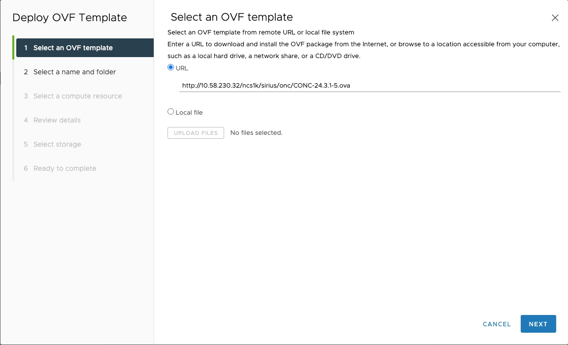
  • Before installing Cisco Optical Network Controller, you must first login in to the VMware customer center and download VMware vCenter server version 7.0, as well as vSphere server and client with version 7.0. Cisco Optical Network Controller is deployed on rack or blade servers within vSphere.


    Attention


    Upgrade to VMware vCenter Server 8.0 U2 if you are using VMware vCenter Server 8.0.2 or VMware vCenter Server 8.0.1.


  • Install ESXi host version of 7.0 or higher on the servers to support creating Virtual Machines.

  • You must have a DNS server. The DNS server can be an internal DNS server if the Cisco Optical Network Controller instance is not exposed to the internet.

  • You must have an NTP server or NTP Pool for time synchronization. Configure the same NTP server or pool on Cisco Optical Network Controller and the PC or VM you use to access Cisco Optical Network Controller. Configure the ESXi host also with the same NTP configuration.

  • Before the Cisco Optical Network Controller installation, two networks must be created.

    • Control Plane Network:

      The control plane network helps in the internal communication between the deployed VMs within a cluster. If you are setting up a standalone system, this can refer to any private network. However, in case of a High Availability (HA) cluster, this network is created between the servers where each node of the HA cluster is being created.

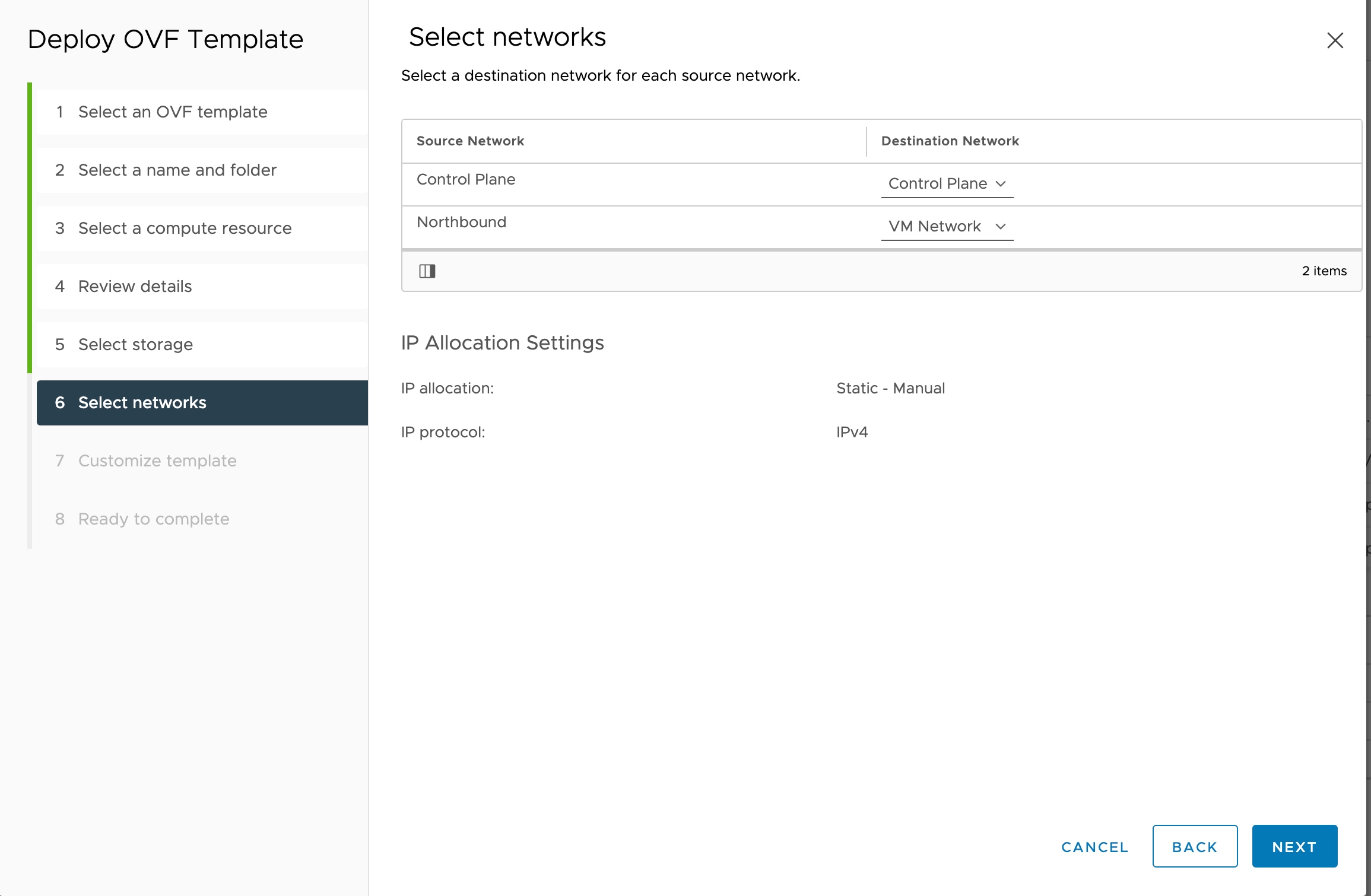
    • VM Network or Northbound Network:

      The VM network is used for communication between the user and the cluster. It handles all the traffic to and from the VMs running on your ESXi hosts and this is your public network through which the UI is hosted.

    • Eastbound Network:

      The Eastbound Network helps in the internal communication between the deployed VMs within a cluster. If you are setting up a standalone system, this can refer to any private network.

  • Accept the Self-Signed Certificate from the ESXi host.

    1. Access the ESXi host using your web browser.

    2. If you receive a security warning indicating that the connection is not private or that the certificate is not trusted, proceed by accepting the risk or bypassing the warning.


Note


For more details on VMware vSphere, see VMware vSphere.


The minimum hardware requirement for Cisco Optical Network Controller installation is given in this table.

Table 1. Minimum Hardware Requirements

Sizing

CPU

Memory

Solid State Drive (SSD)

XS

16 vCPU

64 GB

800 GB

S

32 vCPU

128 GB

1536 GB

M

48 vCPU

256 GB

1536 GB

Storage: SSDs to meet the disk write latency requirement of ≤ 100 ms.


Attention


Cisco Optical Network Controller supports only SSDs for storage.


Note


Configure vCPU and memory according to the VM profile (XS=16vCPU+64GB, S=32vCPU+128GB) before you power on the VM in vCenter.

vCPU to Physical CPU Core Ratio: We support a vCPU to Physical CPU core ratio of 2:1 if hyperthreading is enabled and the hardware supports hyperthreading. Hyperthreading is enabled by default on Cisco UCS servers that support hyperthreading. In other cases, the vCPU to Physical CPU core ratio is 1:1.


The requirements based on type of deployment are given in the table below.

Table 2. Deployment Requirements

Deployment Type

Requirements

Standalone (SA)

Control Plane: One IP (this can be a private network).

Northbound Network/VM Network: 1 IP (this must be a public network)

Highly Available (HA)

Control Plane: Three IPs (this can be a private network) - IPs required for individual nodes.

VM Network: Four IPs (this must be a public network) with 3 IPs for node management and one IP for Virtual IP, which is used for northbound communication and UI.


Note


For a High Availability (HA) deployment, nodes on different ESXi hosts should have a minimum link bandwidth of 10G between them. This is recommended to ensure efficient data communication and synchronization between the nodes.


To create the control plane and virtual management networks follow the steps listed below.

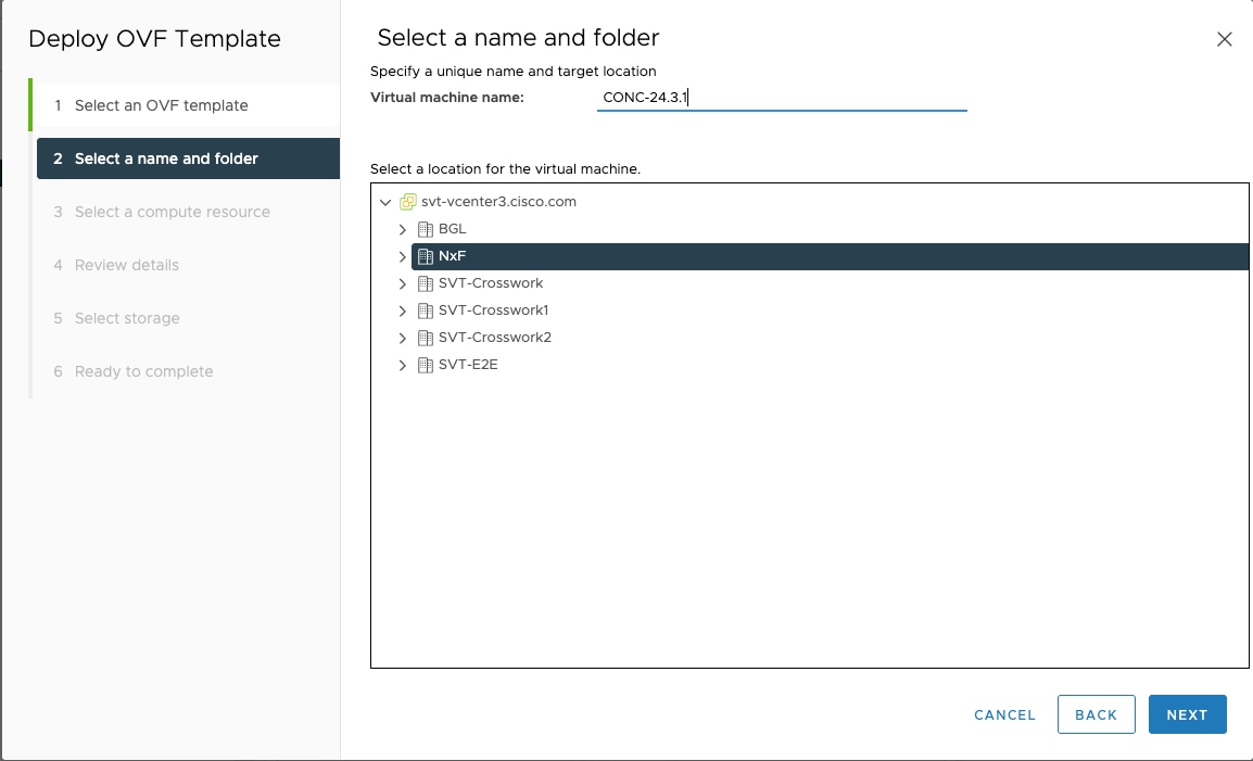
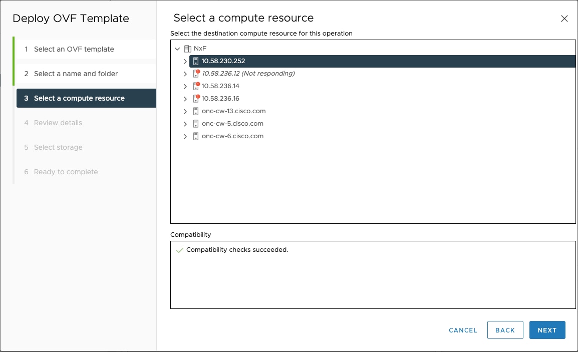
  1. From the vSphere client select the Datacenter where you want to add the ESXi host.

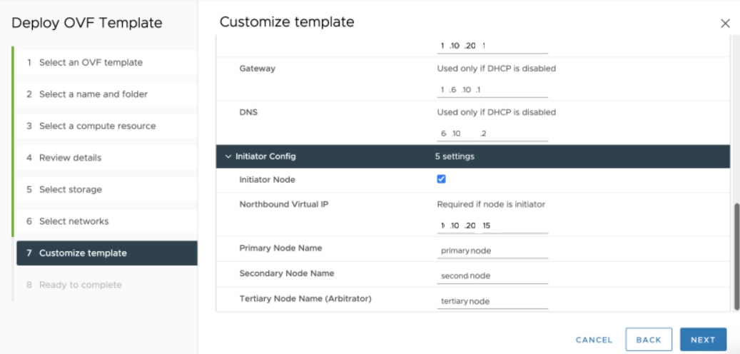
  2. After adding the ESXi host create the Control Plane and VM Networks before deploying the SA or HA. The HA has four IPs where one is the primary and the others can join as secondary and tertiary IP addresses. The SA has only one IP. Also, in the case of HA the Virtual IP is the IP that exposes the active node to the user.

  3. After adding the ESXi host create the Control Plane and Northbound, and Eastbound Networks before deploying.

This table lists the default port assignments.

Table 3. Communications Matrix
Traffic Type Port Description
Inbound TCP 22 SSH remote management
TCP 8443 HTTPS for UI access
Outbound TCP 22 NETCONF to routers
TCP 389 LDAP if using Active Directory
TCP 636 LDAPS if using Active Directory
Customer Specific HTTP for access to an SDN controller
User Specific HTTPS for access to an SDN controller

TCP 3082, 3083,

2361, 6251

TL1 to optical devices

Eastbound

TCP 10443

Supercluster join requests

UDP 8472

VxLAN

syslog User specific TCP/UDP

Control Plane Ports (Internal network between cluster nodes, not exposed)

TCP 443 Kubernetes
TCP 6443 Kubernetes
TCP 10250 Kubernetes
TCP 2379 etcd
TCP 2380 etcd
UDP 8472 VXLAN
ICMP Ping between nodes (optional)

SSH Key Generation

For accessing SSH, ed25519 key is required. The ed25519 key is different from the RSA key.

Use the following CLI to generate the ed25519 key.

ssh-keygen -t ed25519
Generating public/private ed25519 key pair.
Enter file in which to save the key (/Users/xyz/.ssh/id_ed25519): ./<file-name-of-your-key>.pem
Enter passphrase (empty for no passphrase):
Enter same passphrase again:
Your identification has been saved in ./<file-name-of-your-key>.pem
Your public key has been saved in ./<file-name-of-your-key>.pem.pub
The key fingerprint is:
SHA256:zGW6aGn8rxvEq82sA/97jOaHrl9rnoTaYi+TqU3MeRU xyz@abc
The key's randomart image is:
+--[ED25519 256]--+
|                 |
|                 |
|          E      |
|       + + .     |
|        S .      |
|    .+ = =       |
|     o@o*+o      |
|     =XX++=o     |
|    .o*#/X=      |
+----[SHA256]-----+

#Once created you can cat the file with .pub extension for the public key. ( ex: <file-name-of-your-key>.pem.pub )

cat <file-name-of-your-key>.pem.pub
#The above key has to be used in the deployment template ( SSH Public Key ) in the Deployment process

Install Cisco Optical Network Controller Using VMware vSphere

The Cisco Optical Network Controller is distributed as a single OVA file, which is a disk image deployed using vCenter on any ESXi host. This OVA includes several components, such as a file descriptor (OVF) and virtual disk files that contain a basic operating system and the Cisco Optical Network Controller installation files. It can be deployed on ESXi hosts supporting standalone (SA) or supercluster deployment models.

To deploy the OVA template, follow the steps given below.

Before you begin


Note


During the OVF deployment, the deployment gets aborted if there is an internet disconnection.


Procedure


Step 1

Right-click the ESXi host in the vSphere client screen and click Deploy OVF Template.

Step 2

In the Select an OVF template screen, select the URL radio button for specifying the URL to download and install the OVF package from the Internet or select the Local file radio button to upload the downloaded ova files from your local system and click Next.

Figure 1. Select an OVF Template
screenshot

Step 3

In the Select a name and folder screen, specify a unique name for the virtual machine Instance. Cisco Optical Network Controller can be deployed as Standalone or High Availability. From the list of options, select the location of the VM to be used as Standalone or High Availability (primary, secondary, or tertiary) and click Next.

Figure 2. Select a name and folder
screenshot

Step 4

In the Select a compute resource screen, select the destination compute resource on which you want to deploy the VM and click Next.

Figure 3. Select a Compute Resource
screenshot

Note


While selecting the compute resource the compatibility check proceeds till it completes successfully.

Step 5

In the Review details screen, verify the template details and click Next.

Figure 4. Review Details
screenshot

Step 6

In the Select storage screen, select the virtual disk format based on provision type requirement. VM Storage Policy is set as Datastore Default and click Next. Select the virtual disk format as Thin Provision.

You must select "Thin provision" as the virtual disk format.

Figure 5. Select Storage
screenshot

Step 7

In the Select networks screen, select the control and management networks as Control Plane, Eastbound, and Northbound from the networks created earlier and click Next.

Figure 6. Select Networks
screenshot

Step 8

In the Customize template screen, set the values using the following table as a guideline for deployment.

Figure 7. Customize Template
Screenshot of Customize template one
Screenshot of Customize template two
Screenshot of Customize template three
Table 4. Customize Template
Key Values
Instance Hostname <instance hostname>
SSH Public Key <ssh-public-key>. Used for SSH access that allows you to connect to the instances securely without the need to manage credentials for multiple instances. SSH public key must be a ed25519 key.

Node Name

Enter the string: primary

Node Name

<primary/secondary/tertiary>

Must be a valid DNS name per RFC1123.1.2.4

  • Contain at most 63 characters.

  • Contain only lowercase alphanumeric characters or '-'.3

  • Start with an alphanumeric character.

  • End with an alphanumeric character. Standalone: primary, High Availability: primary, secondary or tertiary in accordance with the node role.

Data Volume Size (GB) <recommended-size> The data storage limit is set for the host with 200GB is as minimum value.
Cluster Join Token <token-value> This is a pre-filled value.
Control Plane Node Count <CP-node-count> One for Standalone and three for High Availability.
Control Plane IP <ip/subnet> It is the private IP for the instance which is the dedicated control plane IP for this node from the control plane network.

Note


Subnet is a mandatory field and must be specified in the template.

Initiator IP <> Initiator IP should be matching the control plane IP of the node, which is marked as the initiator node as part of this template. We recommend using the primary node as the Initiator node. Use the control plane IP of the primary node.

Standalone: Same as the control plane IP.

High Availability: control plane IP of the primary node in all three repetitions of the deployment.

Protocol Static or DHCP IP address.
IP (IP[/subnet]) - if not using DHCP <ip/subnet> It is the public IP for the instance in Northbound Network. This IP is used for managing the node and comes from the Northbound network or VM network. It can be used for SSH to the particular node. In case of High Availability, three distinct IP addresses are used.

Note


Subnet is a mandatory field and must be specified in the template.

Gateway - if not using DHCP <gateway-ip for the instance> Northbound Network.
DNS DNS Server IP. A valid DNS accessible from the network is required.
Initiator Node

This node is set to ‘True’ by checking it for the control plane IP. In case of Standalone, it is set as 'True' for the control plane IP of the single node. In case of high availability it is set to 'True' by checking it only for the Initiator node, which is the primary node for the Control Plane IP, similar to Standalone.

Northbound Virtual IP <IP> It is same as public IP for the Instance for the Northbound Network. It is used for all the northbound connections, such as UI and RESTCONF.

For Standalone this IP is the same as the Northbound Network/VM Network IP of the primary node. For High Availability, we recommend using a distinct IP from Northbound Network/VM Network and must be the same for all 3 nodes.

Primary Node Name

It is a string and is the name of the primary node. It must remain the same all the three times in case of High Availability. Use the node name that you chose for the primary node in node config.

Secondary Node Name

It is a string and is the name of the secondary node. Use the node name that you chose for the secondary node in node config.

Tertiary Node Name

It is a string and is the name of the tertiary node. Use the node name that you chose for the tertiary node in node config.

Step 9

In Review the details screen, review all your selections and click Finish. To check or change any properties from the review screen anytime, before clicking Finish click BACK to go back to the previous screen Customize template to add your changes.

Figure 8. Ready to Complete
screenshot

Step 10

Using the steps above from step 1 to 8, you can create one VM for Standalone and three VMs for High Availability. In case of High Availability, it is recommended to create all three VMs (primary/secondary/tertiary) before they are turned ON.

Step 11

After the VM is created, power-on the VM and try connecting to the VM using the pem key which was generated earlier, see SSH Key Generation above. For this, use the private key that is generated along with the public key during customizing the public key options.

Attention


Upon activation of the virtual machine (VM), it is designed not to respond to ping requests. However, you can log in using SSH if the installation has been completed successfully.

Step 12

Log in to the VM using the private key.

Note:
  • After the nodes are deployed, the deployment of OVA progress can be checked in the Tasks console of vSphere Client. After Successful deployment Cisco Optical Network Controller takes around 30 minutes to boot.

  • By default, the user ID is admin, and only the password needs to be set. This username is to login to the web UI only. For ssh, the username is nxf.

Step 13

SSH to the node and execute the following CLI command.


ssh -i [ed25519 Private key] nxf@<northbound-vip>
Enter passphrase for key '<file-name-of-your-key>.pem':

Note


Private key is created as part of the key generation with just the .pem extension, and it must be set with the least permission level before using it.

Step 14

SSH to the node and set the initial UI password for the admin user.

For both Standalone and High Availability, execute the following command on any of the nodes.
sedo security user set admin --password

Note


The password policy for the system includes both configurable settings and non-configurable hard requirements to ensure security.

Password Requirements

  • The password must contain at least:

    • 1 uppercase letter

    • 1 lowercase letter

    • 1 number

    • 1 special character

  • Must have a minimum length of 8 characters

Configurable Requirements

You can change the password policy settings using the sedo security password-policy set command. Specify the desired parameters to adjust the configuration:

sedo security password-policy set --expiration-days <number> --reuse-limit <number> --min-complexity-score <number>

Step 15

Use the following CLI command to check and verify which node is active.

root@vc39-es20-ha-171-primary:~# 
root@vc39-es20-ha-171-primary:~# kubectl describe project onc | head
Name:         onc
Namespace:    
Labels:       active=secondary
              standby=primary
Annotations:  <none>
API Version:  nxf.cisco.com/v1alpha1
Kind:         Project
Metadata:
  Creation Timestamp:  2024-02-15T14:29:24Z
  Generation:          2

Step 16

Use the following CLI command to check and verify whether all nodes have joined the cluster or not.

root@vc39-es20-ha-171-primary:~# kubectl get nodes 
NAME        STATUS   ROLES           AGE     VERSION
primary     Ready    control-plane   5d15h   v1.28.5
secondary   Ready    control-plane   5d15h   v1.28.5
tertiary    Ready    control-plane   5d15h   v1.28.5

Note


The steps 16 and 17 above are for High Availability installation.

Step 17

SSH to the node and set the initial UI password for the admin user.

For both Standalone and High Availability, execute the following command on any of the nodes.
sedo security user set admin --password

Note


The password policy for the system includes both configurable settings and non-configurable hard requirements to ensure security.

Password Requirements

  • The password must contain at least:

    • 1 uppercase letter

    • 1 lowercase letter

    • 1 number

    • 1 special character

  • Must have a minimum length of 8 characters

Configurable Requirements

You can change the password policy settings using the sedo security password-policy set command. Specify the desired parameters to adjust the configuration:

sedo security password-policy set --expiration-days <number> --reuse-limit <number> --min-complexity-score <number>

Step 18

Set up the Network Time Protocol (NTP) command to set the NTP server configuration on all the hosts using the following commands.

 vi /etc/chrony.conf
server IP/DNS iburst
# Apply the new ntp setting
systemctl restart chronyd
## To Check the Server
chronyc sources

Note

 
  • You must perform NTP configuration as a superuser.

  • In case of High Availability, the following steps must be executed in all the three nodes.

Step 19

To check the default admin user ID, use the command sedo security user list. To change the default password, use the command sedo security user admin set --password on the CLI console of the VM or through the web UI.

Step 20

Use a web browser to access https://<virtual ip>:8443/ to access the Cisco Optical Network Controller Web UI. Use the admin id and the password you set to log in to Cisco Optical Network Controller.

Note


Access the web UI only after all the onc services are running. Use the sedo system status to verify that all services are running.

Step 21

Check the servicepack status, sedo service list-installed on the SSH of the VM.

#Enable Password Login
sudo vi /etc/ssh/sshd_config


##Add the following Configs
PermitRootLogin Yes
PasswordAuthentication yes


systemctl restart sshd
passwd root ##It promts you to enter the password

Step 22

Cisco Optical Network Controller WebUI can be used for browsing using the IP address. In case of Standalone, the Standalone IP address is used in the URL and in case of High Availability the Virtual IP (VIP) addresses are used in the URL as given here: https://<virtual ip>:8443/

Step 23

Once the setup steps given above are completed successfully, the Cisco Optical Network Controller devices page appears on the screen. Use the admin id and the password to access the installed Cisco Optical Network Controller.

Note


For High Availability deployments, you must set the NETCONF Session Timeout Configuration to no-timeout on COSM before they are onboarded to Cisco ONC.

To configure NETCONF Session Timeout Configuration in COSM, follow the instructions at Configure Netconf and Nodal Craft Session Timeout. Go to: https://<Cisco-Optical-Site-Manager-IP>/#/usersConfiguration?tab=General


Revert to a Previous Version of Cisco Optical Network Controller

This section describes how to revert to the previous version of Cisco Optical Network Controller after you have installed Cisco Optical Network Controller, for both geo-redundant and standalone deployments. This is a manual process—Automatic rollback is not supported. You cannot perform a revert from within Cisco Optical Network Controller.


Restriction


  • Cisco Optical Network Controller does not support downgrading to an older release. To go back to an older version, take a database backup using the SWIMU application and install the older version using the ova file for the release. After installation, restore the database.

  • You can only revert to a previous version if you have created a copy of the target Cisco Optical Network Controller database before upgrading Cisco Optical Network Controller, as described in Backup and Restore Database.


Procedure


For standalone deployments:

  1. Reinstall the previous version of Cisco Optical Network Controller—The version from which you did the backup. See Install Cisco Optical Network Controller Using VMware vSphere.

  2. Follow the procedure to perform database restore from a backup. See Backup and Restore Database.