Amplifier APC

This chapter describes amplifier APC.

Amplifier APC

Amplifier Automatic Power Control (APC) is an optical; application that compensates for span loss variations over time in optical fiber links. This compensation ensures stable optical power levels despite changes in span loss.

Amplifier APC is implemented by two independent control loops:

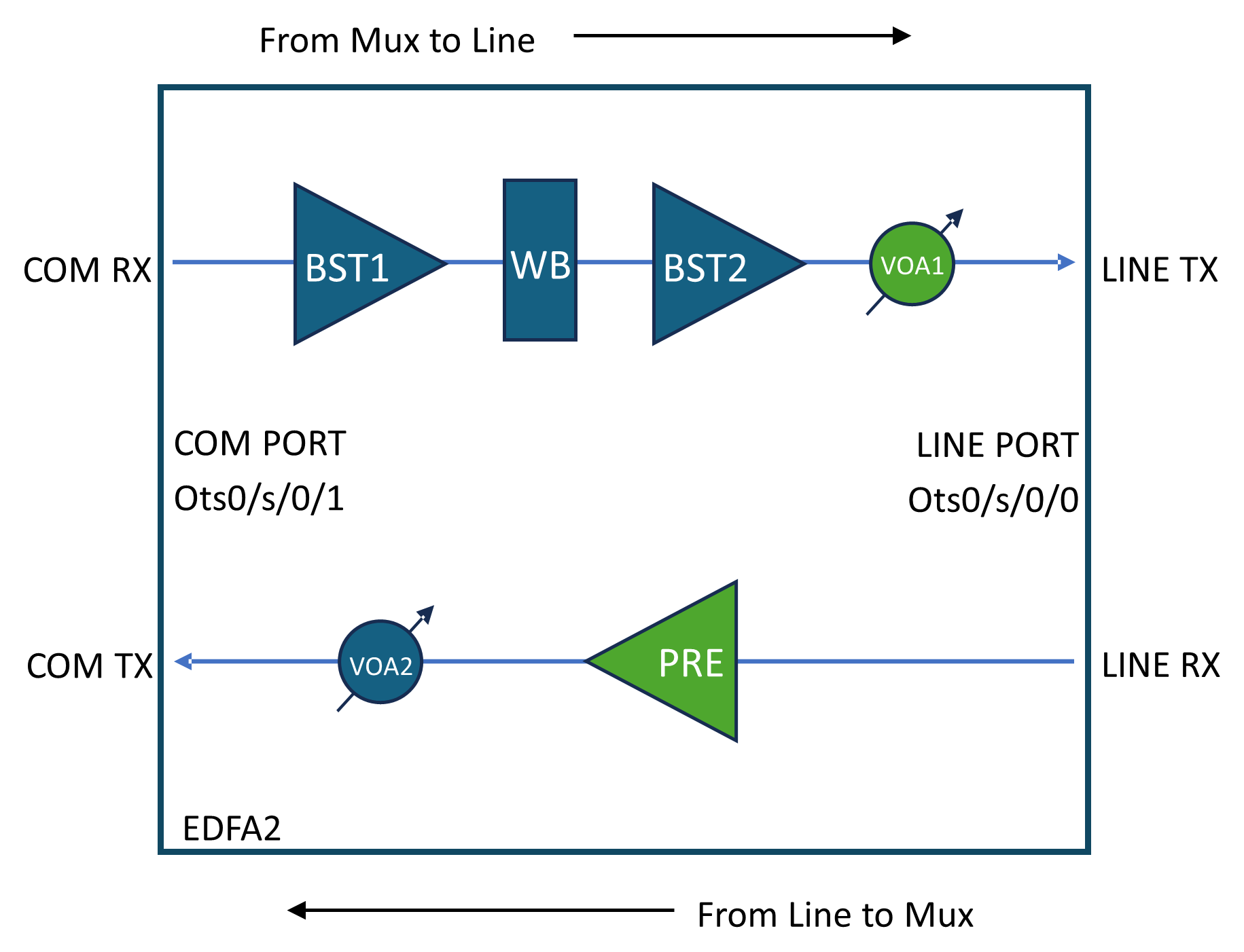
  • Line TX direction: Managed by controller Ots0/<slot>/0/0, which acts on VOA1 attenuation.

  • Line RX direction: Managed by controller Ots0/<slot>/0/1, which acts on PRE-Amplifier Gain.

This diagram shows the NCS1K14-EDFA2 line card optical layout. Optical components controlled by amplifier APC are highlighted in green.

Figure 1. NCS1K14-EDFA2 line card optical layout
NCS1K14-EDFA2 line card optical layout

How amplifier APC works

Summary

Amplifiers APC control loop compensates the span loss variation over time.

Workflow

These are the stages of amplifier apc process.

  1. A span loss variation greater than 0.5 dB triggers the control loops to perform correction.
  2. For a given direction (e.g., from near-end towards far-end), a span loss change is compensated by adjusting:
    • Near-end TX VOA1 attenuation or
    • Far-end RX PRE gain.
  3. Span loss changes are detected by the OLC Span Loss application, which notifies the APC application to trigger a correction. For a given direction, a span loss change is compensated by adjusting the near-end transmit VOA1 attenuation and/or the far-end receive PRE gain.
    • Lookup Table: The VOA attenuation and PRE gain adjustments are derived using an internal lookup table. This table is indexed by Fiber Type and the current Span Loss value, returning the appropriate VOA1 attenuation and PRE gain values. The lookup table defines how much of the span loss variation is compensated by the TX VOA attenuation and how much by the RX PRE gain.
    • PRE Amplifier Saturation Control: An additional control loop is implemented to limit the PRE gain configuration to avoid amplifier saturation, ensuring that the output power does not exceed the maximum allowed value based on the input power and the calculated gain from the lookup table.

Enable Amplifier APC

This topic describes how to enable amplifier APC.

This task describes how to configure amplifier APC. These configurations are in this topic:

  • Enable amplifier APC on COM port

  • Enable amplifier APC on line port

Procedure


Step 1

Use these commands to enable amplifier APC on COM port

configure
optical-line-control
controller ots 0/<slot>/0/1
ampli-apc span-mode
commit
end

Step 2

Use these commands to enable amplifier APC on line port

configure
optical-line-control
controller ots 0/<slot>/0/0
ampli-apc span-mode
commit
end

Disable Amplifier APC

This topic describes how to disable amplifier APC.

This task describes how to configure amplifier APC. These configurations are in this topic:

  • Disable amplifier APC on COM port

  • Disable amplifier APC on line port

Procedure


Step 1

Use these commands to disable amplifier APC on COM port

configure
optical-line-control
controller ots 0/<slot>/0/1
no ampli-apc span-mode
commit
end

Step 2

Use these commands to disable amplifier APC on line port

configure
optical-line-control
controller ots 0/<slot>/0/0
no ampli-apc span-mode
commit
end

Pause Amplifier APC

This topic describes how to pause amplifier APC.

This task describes how to configure amplifier APC. This configuration is in this topic:

  • Pause amplifier APC

Procedure


Use these commands to pause amplifier APC

configure
optical-line-control
controller ots 0/<slot>/0/<port>
ampli-apc-pause
commit
end

Resume Amplifier APC

This topic describes how to configure amplifier APC.

This task describes how to configure amplifier APC. This configuration is in this topic:

  • Resume amplifier APC

Procedure


Use these commands to resume amplifier APC

configure
optical-line-control
controller ots 0/<slot>/0/<port>
no ampli-apc-pause
commit
end

Configure fiber type

This topic describes how to configure fiber type.

This task describes how to configure amplifier APC. This configuration is in this topic:

  • Configure fiber type

Procedure


Use these commands to configure fiber type

configure
optical-line-control
controller ots 0/<slot>/0/1
fiber-type <fiber_type>
commit

Note


Only SMF and E-LEAF fiber types are currently supported by Amplifier APC. If not explicitly configured, SMF fiber type is used by default.


View amplifier APC information

This task describes how to view amplifier APC information.

The Line TX direction control loop acts on VOA1 attenuation and is managed by controller Ots0/<slot>/0/0.

Table 1. Field Descriptions for Line TX:
Field Description
Gain Range BST2 gain range
Last Correction Last VOA1 attenuation correction time stamp
Last Span-Loss Input Last Line TX span loss value measured
Last Span-Loss Input Timestamp Last Line TX span loss measure time stamp
Span-Loss Correction Threshold Threshold below which no correction is triggered
Egress Ampli Input Power BST2 input power
Egress Ampli Gain BST2 gain
Egress Ampli Output Power BST2 output power
TX VOA Attenuation VOA1 attenuation
TX Signal Power Signal power on Line TX

The Line RX direction control loop acts on PRE amplifier gain and is managed by controller Ots0/<slot>/0/1.

Table 2. Field Descriptions for Line RX:
Field Description
Gain Range PRE gain range
Last Correction Last PRE gain correction time stamp
Last Span-Loss Input Last Line RX span loss value measured
Last Span-Loss Input Timestamp Last Line RX span loss measure time stamp
Span-Loss Correction Threshold Threshold below which no correction is triggered
Egress Ampli Input Power PRE input power
Egress Ampli Gain PRE gain
Egress Ampli Output Power PRE output power
TX VOA Attenuation VOA2 attenuation
TX Signal Power Signal power on Com TX
Table 3. Amplifier APC status definitions
Amplifier APC Status Description
BLOCKED

The APC moves to BLOCKED state if:

  • An amplifier safety event like APR or OSRI has been triggered

  • RX-LOS alarm on Ots controllers

  • OTS controller(s) shutdown

PAUSED APC is paused using the ampli-apc-pause command. No regulation is executed on VOA2 or PRE amplifier when in this status.
IDLE APC regulation has been completed successfully; no current adjustments are being made.
REGULATING APC detected a span loss variation and is actively adjusting VOA2 attenuation and/or PRE gain.
Table 4. Reasons for line TX direction APC blocking
Blocking Reason Description
OUTPUT-EDFA-OSRI-ENABLED OSRI triggered on the BST2 amplifier
OUTPUT-EDFA-ALS BST2 amplifier in Auto Laser Shutdown
OUTPUT-OTS-SHUTDOWN Ots controller shutdown (output side)
INPUT-OTS-SHUTDOWN Ots controller shutdown (input side)
Table 5. Reasons for line RX direction APC blocking
Blocking Reason Description
OUTPUT-EDFA-OSRI-ENABLED OSRI triggered on the PRE amplifier
INPUT-EDFA-RX-LOS RX-LOS alarm present on the Ots0/<slot>/0/0 controller
OUTPUT-OTS-SHUTDOWN Ots controller shutdown (output side)
INPUT-OTS-SHUTDOWN Ots controller shutdown (input side)

Procedure


Step 1

To view channel APC information for Line TX direction, use the show olc ampli-apc controller Ots R/S/0/0 regulation-info command.

Example:

Typical output when the Line TX direction control loop is the IDLE state.


RP/0/RP0/CPU0:ios#show olc ampli-apc controller Ots 0/0/0/0 regulation-info 
Mon Jul  7 17:01:56.549 CEST

Controller                               : Ots0/0/0/0
Internal Status                          : IDLE
Gain Range                               : Normal
Last Correction                          : 2025-07-07 15:43:40
Last Span-Loss Input                     : 28.30 dB
Last Span-Loss Input Timestamp           : 2025-07-07 16:49:20
Span-Loss Correction Threshold           : 0.5 dB


  Device Parameters                       Min           Max           Configuration           Operational
============================================================================================================
  Egress Ampli Input Power (dBm)   :      -             -              -                       -33.95   
  Egress Ampli Gain (dB)           :      -             -              -                       35.00     
  Egress Ampli Output Power (dBm)  :      -             22.5           -                       7.99    
  TX VOA Attenuation (dB)          :      0.0           20.0          0.0                      0.20    
  TX Signal Power (dBm)            :      -             -              -                       7.84     

Typical output when the Line TX direction control loop is the BLOCKED state.

RP/0/RP0/CPU0:ios#show olc ampli-apc controller Ots 0/0/0/0 regulation-info 
Mon Jul  7 17:07:39.033 CEST

Controller                               : Ots0/0/0/0
Internal Status                          : BLOCKED
Blocked Reason                           : [ OUTPUT-EDFA-ALS ]
Gain Range                               : Normal
Last Correction                          : 2025-07-07 15:43:40
Last Span-Loss Input                     : 28.30 dB
Last Span-Loss Input Timestamp           : 2025-07-07 16:49:20
Span-Loss Correction Threshold           : 0.5 dB


  Device Parameters                       Min           Max           Configuration           Operational
============================================================================================================
  Egress Ampli Input Power (dBm)   :      -             -              -                       -34.03                   
  Egress Ampli Gain (dB)           :      -             -              -                       0.00                     
  Egress Ampli Output Power (dBm)  :      -             22.5           -                       -50.00                   
  TX VOA Attenuation (dB)          :      0.0           20.0          0.0                      0.00                     
  TX Signal Power (dBm)            :      -             -              -                       -50.00                   

Step 2

To view channel APC information for Line RX direction, use the show olc ampli-apc controller Ots R/S/0/1 regulation-info command.

Example:

Typical output when the Line RX direction control loop is the IDLE state.

RP/0/RP0/CPU0:ios#show olc ampli-apc controller Ots 0/0/0/1 regulation-info 
Mon Jul  7 17:36:51.991 CEST

Controller                               : Ots0/0/0/1
Internal Status                          : IDLE
Gain Range                               : Extended
Last Correction                          : 2025-07-07 12:59:08
Last Span-Loss Input                     : 5.93 dB
Last Span-Loss Input Timestamp           : 2025-07-07 17:22:28
Span-Loss Correction Threshold           : 0.5 dB


  Device Parameters                       Min           Max           Configuration           Operational
============================================================================================================
  Egress Ampli Input Power (dBm)   :      -             -              -                       -18.40                   
  Egress Ampli Gain (dB)           :      20.0          39.0          20.0                     20.00                    
  Egress Ampli Output Power (dBm)  :      -             22.0           -                       1.85                     
  TX VOA Attenuation (dB)          :      -             -              -                       15.00                    
  TX Signal Power (dBm)            :      -             -              -                       -12.89                   

Typical output when the Line RX direction control loop is the BLOCKED state.


RP/0/RP0/CPU0:ios#show olc ampli-apc controller Ots 0/0/0/1 regulation-info 
Mon Jul  7 17:38:23.759 CEST

Controller                               : Ots0/0/0/1
Internal Status                          : BLOCKED
Blocked Reason                           : [ OUTPUT-EDFA-OSRI-ENABLED ]
Gain Range                               : Extended
Last Correction                          : 2025-07-07 12:59:08
Last Span-Loss Input                     : 5.93 dB
Last Span-Loss Input Timestamp           : 2025-07-07 17:22:28
Span-Loss Correction Threshold           : 0.5 dB


  Device Parameters                       Min           Max           Configuration           Operational
============================================================================================================
  Egress Ampli Input Power (dBm)   :      -             -              -                       -18.39                   
  Egress Ampli Gain (dB)           :      20.0          39.0          20.0                     0.00                     
  Egress Ampli Output Power (dBm)  :      -             22.0           -                       -50.00                   
  TX VOA Attenuation (dB)          :      -             -              -                       15.00                    
  TX Signal Power (dBm)            :      -             -              -                       -50.00