Internode Topology Discovery and Communication

Table 1. Feature History

Feature Name

Release Information

Feature Description

Automatic topology discovery

Cisco IOS XR Release 25.1.1

NCS 1014 now supports topology discovery using the OSC links created through the EDFA2 card. To establish the OSC link between two nodes, you need to configure the OSC pluggable to be operational and the OSPFv2 protocol on both the near-end and far-end nodes. By connecting the NCS 1014 to OSPF networks, the NCS 1014 network information is automatically communicated across multiple nodes.

NCS 1014 link topology discovery

Automatic network topology discovery

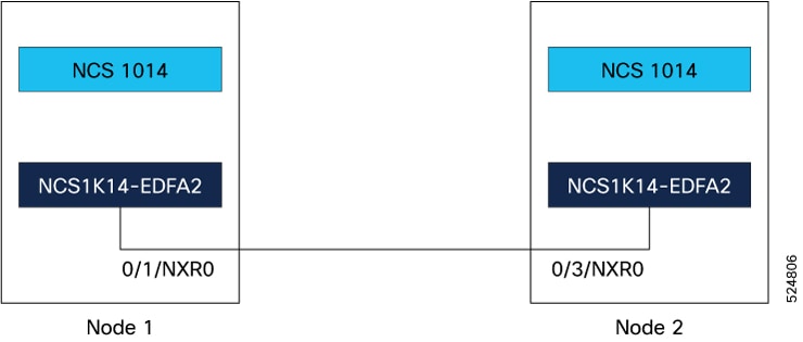
Network topology discovery is automatic when you use an OSC channel created through the EDFA2 card. By connecting the NCS 1014 to Open Shortest Path First (OSPF) networks, NCS 1014 network information is automatically communicated across multiple LANs and WANs. In a network utilizing an OSC channel, all nodes can communicate with each other through this channel.

Understanding OSPF

OSPF is a link-state Internet routing protocol. Link-state protocols monitor their links with adjacent routers and assess the status of their connections to neighbors. These protocols advertise their directly connected networks and active links. Each link-state router compiles these link-state advertisements to form a topology of the entire network or area. From this database, the router calculates a routing table by constructing a shortest path tree. Routes are recalculated when topology changes occur. NCS 1014 supports only OSPFv2.

OSPF protocol in NCS networks

NCS 1014 uses the OSPFv2 protocol within internal NCS networks for node discovery, circuit routing, and node management. Enabling OSPFv2 on the NCS allows the NCS topology to be communicated to OSPF routers on a LAN. This eliminates the need to manually input static routes for NCS subnetworks. OSPF divides networks into smaller regions, called areas, each with a unique ID number, known as the area ID. Every OSPF network includes one backbone area called "area 0," and all other OSPF areas must connect to area 0.

Configure OSPF on the nodes for automatic topology discovery

Use this task to configure OSPFv2 on the near end and far end nodes of the topology shown in this image.

Figure 1. Sample two node topology

OSPFv2 supports only IPv4 addressing.

Figure 2. Two-node topology where OSC link is established

Procedure


Step 1

Configure the interfaces.

  1. Use the interface Loopback command to configure the loopback interface IPv4 address, which is the primary loopback address that you want to reuse for all areas.

    Example:

    Node 1:

    
                                    RP/0/CPU0:ios(config)# interface Loopback 0
                                    RP/0/CPU0:ios(config-if)# ipv4 address 10.10.10.10 255.255.255.255
                                    RP/0/CPU0:ios(config-if)# no shut
                                    RP/0/CPU0:ios(config-if)# exit

    Node 2:

    
                                    RP/0/CPU0:ios(config)# interface Loopback 0
                                    RP/0/CPU0:ios(config-if)# ipv4 address 10.10.10.11 255.255.255.255
                                    RP/0/CPU0:ios(config-if)# no shut
                                    RP/0/CPU0:ios(config-if)# exit
  2. Use the interface GigabitEthernet command to configure the Gigabit Ethernet interface for the OSC link.

    Example:

    Node 1:

    
                                    RP/0/CPU0:ios(config)# interface GigabitEthernet 0/1/0/5
                                    RP/0/CPU0:ios(config-if)# ipv4 point-to-point
                                    RP/0/CPU0:ios(config-if)# ipv4 unnumbered Loopback0 
                                    RP/0/CPU0:ios(config-if)# no shut
                                    RP/0/CPU0:ios(config-if)# exit
                                

    Node 2:

    
                                    RP/0/CPU0:ios(config)# interface GigabitEthernet 0/3/0/5
                                    RP/0/CPU0:ios(config-if)# ipv4 address 10.1.1.2 255.255.255.0
                                    RP/0/CPU0:ios(config-if)# no shut
                                    RP/0/CPU0:ios(config-if)# exit
                                

Step 2

Configure the OSPF process:

  1. Use the router ospf process-name to enable OSPF routing.

  2. Use the distribute link-state keyword to distribute OSPF link-state data.

  3. Use the segment-routing mpls keyword to enable MPLS-based segment routing for the OSPF process.

    This step is optional.

  4. Use the network point-to-point keyword to configure an interface OSPF network type to point-to-point.

  5. Use the area keyword to configure an OSPF area.

Example:

Node 1 and 2:

RP/0/RP0/CPU0:ios(config)# router ospf 1
                        RP/0/RP0/CPU0:ios(config-ospf)#distribute link-state
                        RP/0/RP0/CPU0:ios(config-ospf)#segment-routing mpls
                        RP/0/RP0/CPU0:ios(config-ospf)#area 0

Step 3

Add the configured interfaces to the OSPF area.

Example:

Node 1:

RP/0/RP0/CPU0:ios(config-ospf-ar)# interface Loopback 0
                        RP/0/RP0/CPU0:ios(config-ospf-ar-if)# exit
                        RP/0/RP0/CPU0:ios(config-ospf-ar)# interface GigabitEthernet 0/1/0/5

Node 2:

RP/0/RP0/CPU0:ios(config-ospf-ar)# interface Loopback 0
                        RP/0/RP0/CPU0:ios(config-ospf-ar-if)# exit
                        RP/0/RP0/CPU0:ios(config-ospf-ar)# interface GigabitEthernet 0/3/0/5

Step 4

Exit the OSPF area configuration mode and commit your configuration.

Example:

Node 1 and 2:

RP/0/RP0/CPU0:ios(config-ospf-ar-if)# exit
                        RP/0/RP0/CPU0:ios(config-ospf-ar)# exit
                        RP/0/(config-ospf)# exit 
                        RP/0/RP0/CPU0:ios(config)# commit
                        RP/0/RP0/CPU0:ios(config)# exit

View the topology information

Use this task to view the topology information.

Procedure


Step 1

Use the command show olc internal slot id port id topo-link to view the topology information.

Example:

RP/0/RP0/CPU0:ios# show olc internal slot 0 port 0 topo-link
                        Thu Feb 20 19:53:52.277 IST
                        Self RID: 172.16.0.1
                        Node Type: OLT
                        <OLT><172.16.0.1><0x6a> --- <OLT><192.168.0.1><0x69>

If no neighbors are discovered, an alarm will be triggered at the OSC port.

Example:

RP/0/RP0/CPU0:ios#show alarms brief system active
                        Thu Feb 20 19:54:31.266IST
                        ------------------------------------------------------------------------------------
                        Active Alarms
                        ------------------------------------------------------------------------------------
                        Location  Severity   Group       Set Time                  Description
                        0/1/NXR0  Minor      Software   02/20/2025 19:54:31 IST    Ots0/1/0/0 - Neighbour not found
                    
RP/0/RP0/CPU0:ios#show alarms brief system 
                        Thu Feb 20 19:44:35.212 UTC
                        ------------------------------------------------------------------------------------
                        Active Alarms
                        ------------------------------------------------------------------------------------
                        Location  Severity   Group       Set Time                  Description
                        0/3/NXR0  Minor      Software   02/20/2025 19:14:35 IST    Ots0/3/0/0 - Neighbour not found
                    

Step 2

Use the command show ip ospf neighbor to display OSPF neighbor information on a per-interface basis.

Example:


                        RP/0/RP0/CPU0:ios#show ip ospf neighbor 
                        Thu Feb 20 19:53:53.324 IST
                        
                        * Indicates MADJ interface
                        # Indicates Neighbor awaiting BFD session up
                        
                        Neighbors for OSPF 1
                        
                        Neighbor ID     Pri   State           Dead Time   Address         Interface
                        192.168.0.1     1     FULL/  -        00:00:30    192.168.0.1     GigabitEthernet0/0/0/5
                        Neighbor is up for 00:00:56
                        
                        Total neighbor count: 1

Step 3

Use the show ip interface brief command to view a summary of the router interfaces.

Example:


                        RP/0/RP0/CPU0:ios#show ip interface  brief
                        Thu Feb 20 19:53:54.653 IST
                        
                        Interface                      IP-Address      Status          Protocol   Vrf-Name
                        Loopback0                      10.10.10.10        Up              Up       default 
                        GigabitEthernet0/0/0/5         10.10.10.11        Up              Up       default 
                        GigabitEthernet0/0/0/5         172.16.0.1         Down            Down     default 
                        MgmtEth0/RP0/CPU0/0            10.0.230.189       Up              Up       default 
                        MgmtEth0/RP0/CPU0/1            unassigned      Shutdown          Down      default 
                        PTP0/RP0/CPU0/1                unassigned      Shutdown          Down      default 
                        RP/0/RP0/CPU0:ios#