OTNSec Encryption on the NCS1K14-2.4T-K9 Card

Table 1. Feature History

Product impact

Feature Name

Release Information

Feature Description

Software Reliability

OTNSec encryption and PPP support on the 2.4T card

Cisco IOS XR Release 25.2.1

The 2.4T line card now supports AES-256 GCM authenticated OTNSec encryption using pre-shared keys or certificate-based authentication, ensuring data confidentiality across optical links.

Additionally, PPP over GCC enables secure transmission of control and encryption messages such as IKEv2 exchanges over built-in optical channels, enhancing security and manageability without relying on external interfaces.

The need for high-speed encryption

Importance of network infrastructure security

Most of the emphasis on protecting networks today is focused on securing data within data centers. However, the infrastructure of networks that connect these data centers is equally vulnerable to calculated attacks.

Vulnerability of fiber-optic networks and the necessity of data encryption

As more sensitive information is transmitted across fiber-optic networks, cyber criminals are increasingly focused on intercepting data during its transit across these networks. With the rise in network or fiber-optic hacks, data protection is paramount. Encrypting any data that leaves data centers is becoming a crucial requirement for cloud operators.
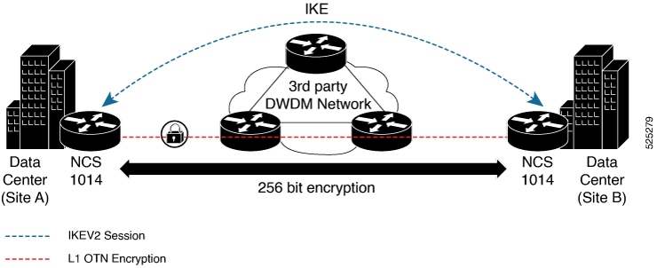
Optical encryption

Optical encryption secures all data on the communications link in and out of a facility, rendering it undecipherable to hackers tapping into the fiber strand. Protecting data at high speeds or line rates is essential for data centers today.

Cisco NCS1014 and OTNSec encryption

Cisco NCS1014 introduces AES256-based OTNSec encryption for 100GE and 400GE clients. Encryption is supported on the 2.4T card.

Role of IKEv2 protocol

OTNSec encryption uses the Internet Key Exchange Version 2 (IKEv2) protocol to negotiate and establish IKEv2 and OTNSec Security Associations (SA). IKEv2 is used for device authentication in an encryption session and provides pre-shared keys (PSK) or RSA certificate-based authentication.

General Communication Channel

General Communication Channel (GCC) is control channel used within the OTN. NCS 1014 supports GCC0 link.

The IKEv2 datagrams are carried as payloads using the point-to-point protocol (PPP) over the GCC channel.

Implementation of IKE sessions

To implement this, an IKE session is established between two endpoints, Site A and Site B, for overhead control plane communication between the two data centers. Data is encrypted at Site A using OTNSec encryption and decrypted at Site B.

The recommended deployment is to have a single IKEv2 session running over a GCC0 channel per trunk port which creates the child Security Associations (SA) for each of the OTNSec controllers that are configured on the trunk port.

Figure 1. OTNSec site-to-site example and components

IKEv2 overview

IKEv2 is a request and response encryption protocol that establishes and handles security associations (SA) in an authentication suite, such as OTNSec, to ensure secure traffic.

IKEv2 is defined in RFC 7296 and consists of the following constructs:

  • Keyring

  • IKEv2 profile

  • IKEv2 proposal

  • IKEv2 policy

Keyring

A keyring is a repository of symmetric and asymmetric pre-shared keys that is configured for a peer and identified using the IP address of the peer. The keyring is associated with an IKEv2 profile and therefore, caters to a set of peers that match the IKEv2 profile. This is a required configuration for the pre-shared keys authentication method that is used for NCS 1004.

IKEv2 profile

An IKEv2 profile is a repository of nonnegotiable parameters of the IKE SA, such as authentication method and services that are available to the authenticated peers that match the profile. The profile match lookup is done based on the IP address of the remote identity.

For security purposes, the IKE SAs have a lifetime that is defined in the IKEv2 profile. The lifetime range, in seconds, is from 120 to 86400. The SAs are rekeyed proactively before the expiry of the lifetime. The default lifetime is 86400.

An IKEv2 profile must be attached to an OTNSec configuration on the ODU controllers on both the IKEv2 initiator and responder. This is a required configuration.

IKEv2 proposal

An IKEv2 proposal is a collection of transforms that are used in the negotiation of IKE SAs as part of the IKE_SA_INIT exchange. The IKE2 proposal must be attached to an IKEv2 policy. This is an optional configuration. The transform types used in the negotiation are as follows:

  • Encryption algorithm

  • Integrity algorithm

  • Pseudo-Random Function (PRF) algorithm

  • Diffie-Hellman (DH) group


Note


The IKEv2 proposal must have at least one algorithm of each type. It is possible to specify multiple algorithms for each type; the order in which the algorithms are specified determines the precedence.


IKEv2 policy

IKEv2 employs policies that are configured on each peer to negotiate handshakes between the two peers. An IKEv2 policy contains proposals that are used to negotiate the encryption, integrity, PRF algorithms, and DH group in the SA_INIT exchange. An IKEv2 policy is selected based on the local IP address. This is an optional configuration.


Note


The default IKEv2 proposal is used with default IKEv2 policy in the absence of any user-defined policy.


How IKEv2 works

In this example, there are two nodes. The node with the lower IP address always acts as the initiator. In this case, node A (R1) has the role of an initiator while Node B (R2) has the role of a responder.

Figure 2. Configuration schema

IKEv2 communications rely on structured request-response pairs called exchanges as shown in this image.

Figure 3. IKEv2 Exchanges
  • IKE performs mutual authentication between two endpoints and establishes an IKE Security Association (SA). At first it exchanges two messages: IKE_SA_INIT and the IKE_AUTH to establish an IKE SA/

  • Subsequently IKE exchanges either CREATE_CHILD_SA or INFORMATIONAL messages.

Benefits of IKEv2

The benefits of IKEv2 include:

Let me know if you'd like it refined further!

  • Reliability and error-processing : IKEv2 uses sequence numbers and acknowledgments to provide reliability and mandates some error-processing logistics and shared state management (windowing).

  • Security features : IKEv2 does not process a request until it determines the requester, helping to mitigate DoS attacks.

  • Dead Peer Detection: IKEv2 provides built-in support for Dead Peer Detection (DPD), which periodically confirms the availability of the peer node. When there is no response from the peer node, the system attempts to establish the session again.

OTNSec encryption overview

The OTNSec encryption feature in the NCS 1014 platform includes these key characteristics:

  • Layer 1 security: Encryption is applied at the OTN layer 1 level, specifically targeting the OPU client payload.

  • Encryption algorithm: The system uses the Galois-Counter-Mode (GCM) AES 256-bit cipher as the default method for encrypting and decrypting OPU payloads.

  • Independent encrypted channels: Each client operates with a separate encrypted channel for both transmission and reception.

  • Programmable key registers: Two banks of 256-bit programmable key registers are available:

    • Current key: Used for ongoing encryption.

    • Future key: Allows for seamless key updates via software without disrupting traffic.

    Each key is associated with an Association Number (AN[1:0]), supporting up to four distinct numbers.

  • Interhost key exchange: Key exchange between hosts is supported through communication over the GCC .

  • Headless mode support: The encryption functionality remains operational even in headless mode.However, headless mode support is timebound and depends on the rekey interval.The maximum supported duration in headless mode is 14 days.

Key concepts in OTNSec encryption and key management

These are the key concepts involved in the OTNSec encryption:

Key generation and function

The OTNSec control plane generates two different keys, one for the transmit (Tx) side and the other for the receive (Rx) side. These keys are used by the line card to program the encryptor and decryptor blocks. These blocks encrypt and decrypt the data packets between the trunk ports of the two nodes.

Key lifetime and rekeying

For security purposes, the keys have a lifetime. A key's lifetime specifies the time the key expires. The "time to expire" (SA lifetime) refers to the period during which a negotiated IKE SA remains valid. The key lifetime for the child SAs can be configured using the sak-rekey-interval which ranges from 30 seconds to 14 days. For example, if the sak-rekey-interval is configured for five minutes, a new key is generated by the OTNSec layer every five minutes. In the absence of a lifetime configuration, the default lifetime is 14.18 days. When the key reaches the maximum lifetime, it becomes invalid, and the CRYPTO-KEY-EXPIRED alarm is raised.

Volume-based rekeying

Volume-based rekeying is supported; the "time to rekey" is the interval before the SA expires, indicating when a new IKE SA must be established to ensure the connection continues without interruption.

it prevents the key from reaching the maximum lifetime. This allows the OTNSec layer to generate a new key when 70% of the lifetime ( approximately11 days) of the current key is over.

Key rollover and indexing

When the lifetime of the first key expires, it automatically rolls over to the next key. To achieve a hitless rollover, the lifetimes of the keys need to be overlapped so that for a certain period of time both keys are active. To maintain this seamless switchover, a key index table is maintained. Each key pair (Tx and Rx) is associated with an Association Number (AN). The index table allows up to four numbers (0, 1, 2, and 3).

Key association and alarms

When the keys are installed, the Rx AN number of node A must match the Tx AN number of node B. Also, the Tx AN number of node A must match the Rx AN number of node B. If there is a mismatch of the AN number between the peer nodes, the CRYPTO-INDEX-MISMATCH alarm is raised.

IKEv2 certificate-based authentication

IKEv2 can use Rivest, Shamir, and Adelman (RSA) digital signatures to authenticate peer devices before setting up Security Associations (SAs). RSA signatures employ a PKI-based method of authentication.

Certification authority interoperability

Certification Authority (CA) interoperability permits Cisco NCS 1014 devices and CAs to communicate for obtaining and using digital certificates. The CA manages certificate requests and issues certificates to participating network devices.

Public key cryptography in RSA

Public key cryptography uses key pairs, such as those in the RSA encryption system, that consist of a public key and a private key. These keys act as complements; anything encrypted with one key can be decrypted with the other.

Digital signatures in RSA

igital signatures are created through encrypting data with a user’s private key. The receiver uses the sender's public key to decrypt the message and verify its signature.The ability to decrypt the message with the sender’s public key indicates that the holder of the private key, the sender, must have created the message.

Configuration workflow

This section describes the workflow to configure IKEv2 and OTNSec encryption on NCS 1014.

Figure 4. OTNSec configuration workflow

Prerequisites

Before proceeding with configuring the OTNSec using IKEV2, ensure that you have:

You can use two authentication methods:

  • Pre-shared keys (PSKs)

  • Certificate-authority (CA)

The configuration workflow using CA-based authentication method involves these sequences:

  1. Configure IKEv2 certificate-based authentication

  2. Configuring IKEv2

  3. Configuring OTNSec

  4. Verify IKEv2 and OTNSec configurations

The configuration workflow using PSK-based authentication method involves these sequences:

  1. Configuring IKEv2

  2. Configuring OTNSec

  3. Verify IKEv2 and OTNSec configurations

Configure IKEv2 certificate-based authentication

Follow these steps to configure IKEv2 certificate-based authentication.

Before you begin

You need to have a CA available to your network before you configure this interoperability feature. The CA must support Cisco Systems PKI protocol, the simple certificate enrollment protocol (SCEP).

Procedure


Step 1

Configure router IP domain name of the router if it is not already configured.

The IP domain name is required because the router assigns a fully qualified domain name (FQDN) to the keys and certificates used by OTNSec, and the FQDN is based on the hostname and IP domain name you assign to the router.

  1. Enter the domain name command to configure the domain name.

  2. Commit the changes

Example:

RP/0/RP0/CPU0:ios#configure
            RP/0/RP0/CPU0:ios(config)#domain name cisco.com
            RP/0/RP0/CPU0:ios(config)#commit
            RP/0/RP0/CPU0:ios(config)#end
          

Step 2

Enter the crypto key generate rsa keypair-label command to generate RSA key pair.

Example:

RP/0/RP0/CPU0:ios#crypto key generate rsa ioxRsa-key
Mon Jun 23 12:21:53.514 UTC
The name for the keys will be: ioxRsa-key
Choose the size of the key modulus in the range of 512 to 4096 for your General Purpose Keypair. Choosing a key modulus greater than 512 may take a few minutes.

How many bits in the modulus [2048]: yes
% A decimal number between 512 and 4096.
How many bits in the modulus [2048]:
Generating RSA keys ...

Done w/ crypto generate keypair
[OK]
RP/0/RP0/CPU0:ios#show  crypto key mypubkey rsa
Mon Jun 23 12:22:17.646 UTC
Key label: ioxRsa-key
Type     : RSA General purpose
Size     : 2048
Created  : 12:21:56 UTC Mon Jun 23 2025
Data     :
30820122 300D0609 2A864886 F70D0101 01050003 82010F00 3082010A 02820101
00DC2099 D283559A 9B38E1EB C7974230 0CFEBD41 5EB03CC1 35DB40AC 3FFC381A
1C1C5E0C 7FD6FD7F 78370B4A 9E5BA840 2CC85FB9 6DAF5CF9 96BAABA5 BFA77BC5
A41BC8F9 9AECABDB 1BD7407A 7A6B0676 8E9B1623 55BEECAD DFD1118F 2F47E4B5
4EB504D1 7B42E02E 0CF9A2C9 2CCEFCB3 21D39377 02E8789E 1CDD9290 71757DBD
E52B5B8E 6E5C5A7F 9A5DF579 3472219A 7D5C1343 F5C07F14 78574C32 101C317B
5FE45888 93776A5F 5187022A 9CE9BC69 C18E38B4 F869605B 4B512BD6 228023D8
680B1F6E E3230BC1 FB9CFC99 8AAC0B37 C4C5679D 8D17DB93 82F6BCBB 9C8E7284
45290D8C AE3F3CFA 31F2F511 5A718445 7E8ADB43 DC6D2E0E 395F9CC6 99A9B9CD
73020301 0001

Key label: the_default
Type     : RSA General purpose
Size     : 2048
Created  : 09:58:19 UTC Fri Jun 06 2025
Data     :
30820122 300D0609 2A864886 F70D0101 01050003 82010F00 3082010A 02820101
00A9B615 1F06AE38 7C843346 BEA57A9C 8557F10F 9DCC46F2 8239A386 A470232B
FE3B807F 16CA1B3C 0FCE8647 96FEB41B 16ABEF6D 246B0EA1 F5F6C7BE F52934B0
F5E88B2C 1E568833 0E4F0678 9FD302D7 B5BB17BB 0158C0A7 48F5B926 D9BBE3D7
F2B74335 D7278113 5EE0CCBA 04B20E41 B2793DE6 BC425537 D84B2197 B8FBD76B
67C03CE2 20A28E62 732FD4B5 9EE80179 045BD6E9 824EB029 766C5F64 E1D56CD2
C6884842 E6B9ADB7 B089F6E6 B5B4C0B3 244451A7 4B09692E 1563FE4C 9BE290AC
AC77F317 D3B7D5C1 DD0C8773 AF30D1C7 A9D78982 F3B52174 3B87DA23 7BA837B1
1F923C7D 1D5BC759 181F5E7B 85339C62 94CD9614 CFA130EA CC9BCAAE 106AA104
9F020301 0001

Step 3

Declare a Certification Authority and configure a trustpoint.

  1. Enter the crypto ca trustpoint command to authenticate the trust point.

  2. Enter the serial-number keyword to specify whether the router serial number should be included in the certificate request.

  3. Enter the crl optional keyword to allow the certificates of other peers to be accepted without trying to obtain the appropriate CRL.

  4. Enter the subject-name keyword to specify the subject name in the certificate request.

  5. Enter the ip-address none keyword to prevent the inclusion of an IP address in the certificate request.

  6. Enter the enrollmenturl keyword, to specify the certification authority (CA) location by naming the CA URL.

  7. Enter the rsakeypair keyword to specify a RSA key pair for this trustpoint.

Note


When you perform a Return Merchandise Authorization (RMA) or swap of an RP card, RSA keys are not stored on the chassis or SSD card and will be removed during the process. Hence you must manually generate new RSA keys and re-establish authentication and enrollment with the CA server. Before proceeding with authentication and enrollment, ensure that you clear any certificates existing on the chassis.

Note


When you delete the trustpoint configuration, you must also clear the certificates associated with the deleted trustpoint using the command clear crypto ca certificates <trustpoint_name>. This step is necessary to prevent potential issues in bringing up the IKEv2 session.

Example:

Near-end node:

RP/0/RP0/CPU0:Node-A(config)#crypto ca trustpoint trust_all_R1
            RP/0/RP0/CPU0:Node-A(config-trustp)# crl optional
            RP/0/RP0/CPU0:Node-A(config-trustp)# ip-address none
            RP/0/RP0/CPU0:Node-A(config-trustp)#subject-name CN=Acadia.cisco.com,OU=SPBU,O=Cisco Systems,L=Bengaluru,ST=KA,C=IN
            RP/0/RP0/CPU0:Node-A(config-trustp)# serial-number none
            RP/0/RP0/CPU0:Node-A(config-trustp)# enrollment url http://10.105.57.29:8080/scep
            RP/0/RP0/CPU0:Node-A(config-trustp)# rsakeypair ioxRsa-key
            RP/0/RP0/CPU0:Node-A(config-trustp)#commit
          

Far-end Node:

RP/0/RP0/CPU0:Node-B(config)#crypto ca trustpoint trust_all_R2
            RP/0/RP0/CPU0:Node-B(config-trustp)# crl optional
            RP/0/RP0/CPU0:Node-B(config-trustp)# ip-address none
            RP/0/RP0/CPU0:Node-B(config-trustp)# subject-name CN=Acadia.cisco.com,OU=SPBU,O=Cisco Systems,L=Bengaluru,ST=KA,C=IN
            RP/0/RP0/CPU0:Node-B(config-trustp)# serial-number none
            RP/0/RP0/CPU0:Node-B(config-trustp)# enrollment url http://10.105.57.29:8080/scep
            RP/0/RP0/CPU0:Node-B(config-trustp)# rsakeypair ioxRsa-key
            RP/0/RP0/CPU0:Node-B(config-trustp)#commit
          

Step 4

Enter the crypto ca authenticate ca-name command to authenticate the CA.

The router must authenticate the CA by obtaining the self-signed certificate of the CA, which contains the public key of the CA. Because the certificate of the CA is self-signed (the CA signs its own certificate), manually authenticate the public key of the CA by contacting the CA administrator to compare the fingerprint of the CA certificate.

Example:

RP/0/RP0/CPU0:ios# crypto ca authenticate trust_all_R1
Mon Jun 23 12:30:17.758 UTC
Serial Number  : 01
Subject:
CN=MICROMDM SCEP CA,OU=SCEP CA,O=scep-ca,C=US
Issued By      :
CN=MICROMDM SCEP CA,OU=SCEP CA,O=scep-ca,C=US
Validity Start : 03:39:43 UTC Wed Jan 08 2025
Validity End   : 03:39:43 UTC Mon Jan 08 2035
SHA1 Fingerprint:
853C4D0216E35AE2F765FA1F274BBD238080D06F
Do you accept this certificate? [yes/no]: yes
RP/0/RP0/CPU0:ios#

Step 5

Enter the crypto ca enroll ca-name command to request the device certificates.

You must obtain a signed certificate from the CA for each of your router’s RSA key pairs.

Example:

RP/0/RP0/CPU0:ios#crypto ca enroll trust_all_R1
Mon Jun 23 12:30:32.506 UTC
% Start certificate enrollment ... 
% Create a challenge password. You will need to verbally provide this
  password to the CA Administrator in order to revoke your certificate.
% For security reasons your password will not be saved in the configuration.
% Please make a note of it.

Password: 
Re-enter Password: 

% The subject name in the certificate will include: CN=Acadia.cisco.com,OU=SPBU,O=Cisco Systems,L=Bengaluru,ST=KA,C=IN
% The subject name in the certificate will include: 175_ne.cisco.com
% Include the router serial number in the subject name? [yes/no]: no
% The IP address in the certificate is 0.0.0.0
    Fingerprint:  34463337 30304543 44313936 36443031

Note


It is crucial to ensure that the certificate is valid and not expired. Verifying its validity in advance is essential, as an expired certificate could cause traffic disruptions, particularly in the presence of RP-related issues.


Configure the parameters for IKEv2 proposal

Follow these steps to configure various parameters for the IKEv2 proposal.

Procedure


Step 1

Enter the ikev2 proposal command to configure an IKEv2 proposal and to specify an IKEv2 proposal name.

Step 2

Enter the encryption keyword to specify the transform types for encryption.

Step 3

Enter the integrity keyword to specify one or more transforms of the integrity algorithm type.

Step 4

Enter the prf keyword to specify the Pseudo-Random Function (PRF) algorithm type.

Step 5

Enter the dh keyword to specify the Diffie-Hellman group for the IKEv2 proposal.

Step 6

Commit the changes.

Example:

Near-end node:

RP/0/RP0/CPU0:Node-A(config)#ikev2 proposal ikev2_proposal_all_0_3
RP/0/RP0/CPU0:Node-A(config-ikev2-proposal-ikev2_proposal_al)# prf sha-1
RP/0/RP0/CPU0:Node-A(config-ikev2-proposal-ikev2_proposal_al)# dh-group 19
RP/0/RP0/CPU0:Node-A(config-ikev2-proposal-ikev2_proposal_al)# encryption aes-gcm-128
RP/0/RP0/CPU0:Node-A(config-ikev2-proposal-ikev2_proposal_al)#commit
Thu Mar 7 19:20:30.916 UTC
RP/0/RP0/CPU0:Node-A(config-ikev2-proposal-proposal1)#exit 
RP/0/RP0/CPU0:Node-A(config)#exit

Far-end node:

RP/0/RP0/CPU0:Node-B(config)#ikev2 proposal ikev2_proposal_all_0_0
RP/0/RP0/CPU0:Node-B(config-ikev2-proposal-ikev2_proposal_al)# prf sha-1
RP/0/RP0/CPU0:Node-B(config-ikev2-proposal-ikev2_proposal_al)# dh-group 19
RP/0/RP0/CPU0:Node-B(config-ikev2-proposal-ikev2_proposal_al)# encryption aes-gcm-128
RP/0/RP0/CPU0:Node-B(config-ikev2-proposal-ikev2_proposal_al)#commit

Create an IKEv2 policy

Follow these steps to create an IKEv2 policy.

Procedure


Step 1

Enter the ikev2 policy command, to specify an IKEv2 policy.

Step 2

Enter the proposal keyword to specify the IKEv2 proposal for the IKEv2 policy.

Step 3

Enter the match address local keyword to specify a match type and the IP address of the local interface to be associated with this IKEv2 profile.

Step 4

Commit the changes.

Example:

Near-end node:

RP/0/RP0/CPU0:Node-A(config)#ikev2 policy ikev2_policy_all_0_3
         RP/0/RP0/CPU0:Node-A(config-ikev2-policy-ikev2_policy_all_0_)# match address local 10.1.1.1
         RP/0/RP0/CPU0:Node-A(config-ikev2-policy-ikev2_policy_all_0_)# proposal ikev2_proposal_all_0_3
         RP/0/RP0/CPU0:Node-A(config-ikev2-policy-ikev2_policy_all_0_)#commit

Far-end node:

RP/0/RP0/CPU0:Node-B(config)#ikev2 policy ikev2_policy_0_0
         RP/0/RP0/CPU0:Node-B(config-ikev2-policy-ikev2_policy_0_0)# match address local 10.1.1.2
         RP/0/RP0/CPU0:Node-B(config-ikev2-policy-ikev2_policy_0_0)# proposal ikev2_proposal_all_0_0
         RP/0/RP0/CPU0:Node-B(config-ikev2-policy-ikev2_policy_0_0)#commit
          

Create a keyring with pre shared keys

Follow these steps to create a keyring with the postquantum preshared keys.

Procedure


Step 1

Enter the keyring command to configure a keyring profile.

Step 2

Enter the peer name keyword to specify the name of the peer interface.

Step 3

Enter the pre-shared-key keyword to configure the preshared keys for authentication.

Step 4

Enter the address ip keyword to specify the IP address of the peer interface along with the prefix.

Example:

Near-end node:

RP/0/RP0/CPU0:Node-A#configure
RP/0/RP0/CPU0:Node-A(config)#keyring KR1
RP/0/RP0/CPU0:Node-A(config-keyring-KR1)#peer Node-B
RP/0/RP0/CPU0:Node-A(config-keyring-KR1-peer-Node-B)#address 10.1.1.1 255.255.255.0
RP/0/RP0/CPU0:Node-A(config-keyring-KR1-peer-Node-B)#pre-shared-key password cisco123!cisco123
RP/0/RP0/CPU0:Node-A(config-keyring-KR1-peer-Node-B)#commit
RP/0/RP0/CPU0:Node-A(config-keyring-KR1-peer-Node-B)#exit
RP/0/RP0/CPU0:Node-A(config-keyring-KR1)#exit

Far-end node:

RP/0/RP0/CPU0:Node-B#configure
RP/0/RP0/CPU0:Node-B(config)#keyring KR1
RP/0/RP0/CPU0:Node-B(config-keyring-KR1)#peer Node-A
RP/0/RP0/CPU0:Node-B(config-keyring-KR1-peer-Node-A)#address 10.1.1.2 255.255.255.0
RP/0/RP0/CPU0:Node-B(config-keyring-KR1-peer-Node-A)#pre-shared-key password cisco135!cisco135
RP/0/RP0/CPU0:Node-B(config-keyring-KR1-peer-Node-A)#commit
RP/0/RP0/CPU0:Node-B(config-keyring-KR1-peer-Node-A)#exit
RP/0/RP0/CPU0:Node-B(config-keyring-KR1)#exit

Create an IKEv2 profile that will be attached to the OTNSec profile (PSK authentication method)

Follow these steps to create an IKEv2 profile that will be attached to the OTNSec profile.

Procedure


Step 1

Enter the ikev2 profile command to specify the name of an IKEv2 profile.

Step 2

Enter the lifetime keyword to configure the lifetime of IKEv2 security association (SA).

Step 3

Enter the keyring <keyring name>keyword to specify the details of the IKEv2 keyring that consists of the preshared keys.

Step 4

Enter the match remote address keyword to specify the IP address of the remote node.

Step 5

Commit the changes.

Example:

Near-end node:

RP/0/1/CPU0:Node-A(config)#ikev2 profile profile1
RP/0/1/CPU0:Node-A(config-ikev2-profile-profile1)#keyring KR1
RP/0/RP0/CPU0:Node-A(config-ikev2-profile-profile1)#lifetime 86400
RP/0/RP0/CPU0:Node-A(config-ikev2-profile-profile1)#match address 10.1.1.1 255.255.255.0
RP/0/RP0/CPU0:Node-A(config-ikev2-profile-profile1)#commit

Far-end node:

RP/0/1/CPU0:Node-B(config)#ikev2 profile profile1
RP/0/1/CPU0:Node-B(config-ikev2-profile-profile1)#keyring dynamic
RP/0/RP0/CPU0:Node-B(config-ikev2-profile-profile1)#lifetime 86400
RP/0/RP0/CPU0:Node-B(config-ikev2-profile-profile1)#match address 10.1.1.2 255.255.255.0
RP/0/RP0/CPU0:Node-B(config-ikev2-profile-profile1)#commit

Create an IKEv2 profile that will be attached to the OTNSec profile (CA authentication method)

Follow these steps to create an IKEv2 profile that will be attached to the OTNSec profile.

Procedure


Step 1

Enter the ikev2 profile command to specify the name of an IKEv2 profile.

Step 2

Enter the lifetime keyword to configure the lifetime of IKEv2 security association (SA).

Step 3

Enter the match identity remote address keyword to specify the IP address of the remote node.

Step 4

Enter the pki trustpoint keyword to specify public key infrastructure name in the OTNSec profile.

Step 5

Enter the authentication keyword to specify that the OTNSec Peer authentication method to be followed.

Step 6

Enter the local and remote keywords to specify that the authentication occurs on the source router and the peer router.

Step 7

Enter the rsa-signature keyword to specify that the authentication is X.509v3 certificate based on rsa signature.

Step 8

Commit the changes.

Example:

Near-end node:

RP/0/RP0/CPU0:Node-A(config)#ikev2 profile profile_all_0_3
RP/0/RP0/CPU0:Node-A(config-ikev2-profile-profile_all_0_3)# match fvrf vrf2
RP/0/RP0/CPU0:Node-A(config-ikev2-profile-profile_all_0_3)# match identity remote address 10.1.1.2 255.255.255.0
RP/0/RP0/CPU0:Node-A(config-ikev2-profile-profile_all_0_3)# pki trustpoint trust_all_R1
RP/0/RP0/CPU0:Node-A(config-ikev2-profile-profile_all_0_3)# lifetime 86400
RP/0/RP0/CPU0:Node-A(config-ikev2-profile-profile_all_0_3)# authentication local rsa-signature
RP/0/RP0/CPU0:Node-A(config-ikev2-profile-profile_all_0_3)# authentication remote rsa-signature
RP/0/RP0/CPU0:Node-A(config-ikev2-profile-profile_all_0_3)#commit

Far-end node:

RP/0/RP0/CPU0:Node-B(config)#ikev2 profile profile_all_0_0
RP/0/RP0/CPU0:Node-B(config-ikev2-profile-profile_all_0_0)#match fvrf vrf2
RP/0/RP0/CPU0:Node-B(config-ikev2-profile-profile_all_0_0)#match identity remote address 10.1.1.1 255.255.255.0
RP/0/RP0/CPU0:Node-B(config-ikev2-profile-profile_all_0_0)# pki trustpoint trust_all_R2
RP/0/RP0/CPU0:Node-B(config-ikev2-profile-profile_all_0_0)# lifetime 86400
RP/0/RP0/CPU0:Node-B(config-ikev2-profile-profile_all_0_0)# authentication local rsa-signature
RP/0/RP0/CPU0:Node-B(config-ikev2-profile-profile_all_0_0)# authentication remote rsa-signature
RP/0/RP0/CPU0:Node-B(config-ikev2-profile-profile_all_0_0)#
RP/0/RP0/CPU0:Node-B(config-ikev2-profile-profile_all_0_0)#commit

Configure the OTNSec policy

Follow these steps to configure the OTNSec policy in near-end and far-end nodes.

Procedure


Step 1

Enter the otnsec policy command to configure an OTNSec policy.

Step 2

Enter the cipher-suite keyword to specify the encryption algorithm for an OTNSec policy.

Step 3

Enter the security-policy must-secure keyword to specify the security for OTNSec policy.

Step 4

Enter the sak-rekey-interval keyword to configure the key lifetime for the child security associations (SA).

Note


The interval range, in seconds, is from 30 to 1209600. If SAK rekey timer is not configured, the system sets it at a default value of 898393.

Step 5

Commit the changes.

Example:

Near-end node:

RP/0/RP0/CPU0:Node-A(config)#otnsec policy otnsec_policy_all_0_3
RP/0/RP0/CPU0:Node-A(config-otnsec-policy)# cipher-suite AES-GCM-256
RP/0/RP0/CPU0:Node-A(config-otnsec-policy)# security-policy must-secure
RP/0/RP0/CPU0:Node-A(config-otnsec-policy)# sak-rekey-interval 28800
RP/0/RP0/CPU0:Node-A(config-otnsec-policy)#commit

Far-end node:

RP/0/RP0/CPU0:Node-B#configur
Tue Apr 29 13:48:20.494 UTC
RP/0/RP0/CPU0:Node-B(config)#otnsec policy otnsec_policy_all_0_0
RP/0/RP0/CPU0:Node-B(config-otnsec-policy)# cipher-suite AES-GCM-256
RP/0/RP0/CPU0:Node-B(config-otnsec-policy)# security-policy must-secure
RP/0/RP0/CPU0:Node-B(config-otnsec-policy)# sak-rekey-interval 28800
RP/0/RP0/CPU0:Node-B(config-otnsec-policy)#commit

Configure the GCC0 interface

Follow these steps to configure GCC0 interface on the near-end and far-end nodes.

Procedure


Step 1

Enter the command CoherentDSP R/S/I/P in the configuration mode, to configure the odu-flex controller.

Step 2

Enter the gcc0 keyword to enable the GCC0 interface.

Step 3

Commit the changes and exit.

Step 4

Enter the interface gcc0 R/S/I/P command, to configure the GCC0 interface.

Step 5

Enter the ipv4 address keyword to specify the encryption algorithm for an OTNSec policy.

Step 6

Commit the changes.

Example:

Near-end node:

RP/0/RP0/CPU0:Node-A(config)#controller CoherentDSP0/3/0/7
RP/0/RP0/CPU0:Node-A(config-CoDSP)# gcc0
RP/0/RP0/CPU0:Node-A(config-CoDSP)#commit

RP/0/RP0/CPU0:Node-A(config)#interface GCC00/3/0/7
RP/0/RP0/CPU0:Node-A(config-if)# ipv4 address 10.1.1.1 255.255.255.0
RP/0/RP0/CPU0:Node-A(config-if)#commit

Far-end node:

RP/0/RP0/CPU0:Node-B(config)#controller CoherentDSP0/0/0/0
RP/0/RP0/CPU0:Node-B(config-CoDSP)# gcc0
RP/0/RP0/CPU0:Node-B(config-CoDSP)#commit

RP/0/RP0/CPU0:Node-B(config)#interface GCC00/0/0/0
RP/0/RP0/CPU0:Node-B(config-if)# ipv4 address 10.1.1.2 255.255.255.0
RP/0/RP0/CPU0:Node-B(config-if)#commit

Configure the OTNSec on ODU flex controller

Follow these steps to OTNSec on the ODU flex controller on the near-end and far-end nodes.

Procedure


Step 1

Enter the command controller odu-flex R/S/I/P to configure the ODU flex controller.

Step 2

Enter the otnsec keyword to configure OTNSec.

Step 3

Enter the source ipv4 and destination ip4 keywords to specify the ip addresses of the local and remote nodes.

Step 4

Enter the session id keyword to configure the session id for the OTNSec.

The session ID ranges 1–65535.

Step 5

Enter the policy keyword to specify the OTNSec policy that was configured.

Step 6

Enter the IKEv2 keyword to specify the ikev2 profile.

Step 7

Commit the changes.

Example:

Near-end node:

RP/0/RP0/CPU0:Node-A(config)#controller ODU-FLEX0/3/0/7/4
RP/0/RP0/CPU0:Node-A(config-oduflex)# otnsec
RP/0/RP0/CPU0:Node-A(config-otnsec)#  policy otnsec_policy_all_0_3
RP/0/RP0/CPU0:Node-A(config-otnsec)#  ikev2 profile_all_0_3
RP/0/RP0/CPU0:Node-A(config-otnsec)#  source ipv4 10.1.1.1
RP/0/RP0/CPU0:Node-A(config-otnsec)#  destination ipv4 10.1.1.2
RP/0/RP0/CPU0:Node-A(config-otnsec)#  session-id 60
RP/0/RP0/CPU0:Node-A(config-otnsec)#commit

Far-end node:

RP/0/RP0/CPU0:Node-B(config)#controller ODU-FLEX0/0/0/0/1
RP/0/RP0/CPU0:Node-B(config-oduflex)# otnsec
RP/0/RP0/CPU0:Node-B(config-otnsec)#  policy otnsec_policy_all_0_0
RP/0/RP0/CPU0:Node-B(config-otnsec)#  ikev2 profile_all_0_0
RP/0/RP0/CPU0:Node-B(config-otnsec)#  source ipv4 10.1.1.2
RP/0/RP0/CPU0:Node-B(config-otnsec)#  destination ipv4 10.1.1.1
RP/0/RP0/CPU0:Node-B(config-otnsec)#  session-id 60
RP/0/RP0/CPU0:Node-B(config-otnsec)#commit

Verify IKEv2 and OTNSec configurations

Follow these steps to view the various configurations done for IKEv2 and OTNSec.

Procedure


Step 1

Enter the show ikev2 session detail command to view the details of IKEv2 sessions configured.

Example:

Near-end node:

RP/0/RP0/CPU0:Node-A#show ikev2 session detail
Tue Apr 29 13:49:08.907 UTC

Session ID                             : 9
===============================================================================
 Status                                : UP-ACTIVE
 IKE Count                             : 1
 Child Count                           : 1
 IKE SA ID                             : 24219
-------------------------------------------------------------------------------
  Local                                : 10.1.1.1/500
  Remote                               : 10.1.1.2/500
  Status(Description)                  : READY (Negotiation done)
  Role                                 : Initiator
  Fvrf                                 : Default
  Encryption/Keysize                   : AES-GCM/128
  PRF/Hash/DH Group                    : SHA1/None/19
  Authentication(Sign/Verify)          : RSA/RSA
  Life/Active Time(sec)                : 86400/732
  Session ID                           : 9
  Local SPI                            : B8F3F6B99303FAEC
  Remote SPI                           : 88942BBDE8EC692C
  Local ID                             : 10.1.1.1
  Remote ID                            : 10.1.1.2
  Quantum resistance                   : Disabled

 Child SA
-------------------------------------------------------------------------------
   Local Selector                      : 10.1.1.1/60 - 10.1.1.1/60
   Remote Selector                     : 10.1.1.2/60 - 10.1.1.2/60
   ESP SPI IN/OUT                      : 0x3c01 / 0x3c01
   Encryption                          : AES-GCM
   Keysize                             : 256
   ESP HMAC                            : None

Far-end node:

RP/0/RP0/CPU0:Node-B#show ikev2 session detail
Tue Apr 29 13:52:07.885 UTC

Session ID                             : 9
===============================================================================
 Status                                : UP-ACTIVE
 IKE Count                             : 1
 Child Count                           : 1
 IKE SA ID                             : 18484
-------------------------------------------------------------------------------
  Local                                : 10.1.1.2/500
  Remote                               : 10.1.1.1/500
  Status(Description)                  : READY (Negotiation done)
  Role                                 : Responder
  Fvrf                                 : Default
  Encryption/Keysize                   : AES-GCM/128
  PRF/Hash/DH Group                    : SHA1/None/19
  Authentication(Sign/Verify)          : RSA/RSA
  Life/Active Time(sec)                : 86400/901
  Session ID                           : 9
  Local SPI                            : 88942BBDE8EC692C
  Remote SPI                           : B8F3F6B99303FAEC
  Local ID                             : 10.1.1.2
  Remote ID                            : 10.1.1.1
  Quantum resistance                   : Disabled

 Child SA
-------------------------------------------------------------------------------
   Local Selector                      : 10.1.1.2/60 - 10.1.1.2/60
   Remote Selector                     : 10.1.1.1/60 - 10.1.1.1/60
   ESP SPI IN/OUT                      : 0x3c01 / 0x3c01
   Encryption                          : AES-GCM
   Keysize                             : 256
   ESP HMAC                            : None

Step 2

Enter the show ikev2 proposal command to view the details of ikev2 proposal.

Example:

Near-end node:

RP/0/RP0/CPU0:Node-A#show ikev2 proposal
Tue Apr 29 13:49:27.918 UTC

Proposal Name              : default
=====================================================================================
Status                     : Complete
-------------------------------------------------------------------------------------
Total Number of Enc. Alg.  : 1
   Encr. Alg.              : CBC-AES-256
-------------------------------------------------------------------------------------
Total Number of Hash. Alg. : 2
   Hash. Alg.              : SHA 512
   Hash. Alg.              : SHA 384
-------------------------------------------------------------------------------------
Total Number of PRF. Alg.  : 2
   PRF. Alg.               : SHA 512
   PRF. Alg.               : SHA 384
-------------------------------------------------------------------------------------
Total Number of DH Group   : 3
   DH Group                : Group 19
   DH Group                : Group 20
   DH Group                : Group 21


Proposal Name              : ikev2_proposal_all_0_3
=====================================================================================
Status                     : Complete
-------------------------------------------------------------------------------------
Total Number of Enc. Alg.  : 1
   Encr. Alg.              : GCM-AES-128
-------------------------------------------------------------------------------------
Total Number of Hash. Alg. : 0
-------------------------------------------------------------------------------------
Total Number of PRF. Alg.  : 1
   PRF. Alg.               : SHA 1
-------------------------------------------------------------------------------------
Total Number of DH Group   : 1
   DH Group                : Group 19

Far-end node:

RP/0/RP0/CPU0:Node-B#show ikev2 proposal
Tue Apr 29 13:52:34.596 UTC

Proposal Name              : default
=====================================================================================
Status                     : Complete
-------------------------------------------------------------------------------------
Total Number of Enc. Alg.  : 1
   Encr. Alg.              : CBC-AES-256
-------------------------------------------------------------------------------------
Total Number of Hash. Alg. : 2
   Hash. Alg.              : SHA 512
   Hash. Alg.              : SHA 384
-------------------------------------------------------------------------------------
Total Number of PRF. Alg.  : 2
   PRF. Alg.               : SHA 512
   PRF. Alg.               : SHA 384
-------------------------------------------------------------------------------------
Total Number of DH Group   : 3
   DH Group                : Group 19
   DH Group                : Group 20
   DH Group                : Group 21


Proposal Name              : ikev2_proposal_all_0_0
=====================================================================================
Status                     : Complete
-------------------------------------------------------------------------------------
Total Number of Enc. Alg.  : 1
   Encr. Alg.              : GCM-AES-128
-------------------------------------------------------------------------------------
Total Number of Hash. Alg. : 0
-------------------------------------------------------------------------------------
Total Number of PRF. Alg.  : 1
   PRF. Alg.               : SHA 1
-------------------------------------------------------------------------------------
Total Number of DH Group   : 1
   DH Group                : Group 19

Step 3

Enter the show ikev2 policy to view the details of ikev2 policy.

Example:

Near-end node:

RP/0/RP0/CPU0:Node-A#show ikev2 policy
Tue Apr 29 13:49:47.844 UTC

Policy Name                           : default
===============================================================================
Total number of match local addr      : 1
   Match address local                : Any
-------------------------------------------------------------------------------
Total number of proposal attached     : 1
   Proposal Name                      : default
-------------------------------------------------------------------------------
Total number of fvrf attached         : 1
   Fvrf Name                          : Any


Policy Name                           : ikev2_policy_all_0_3
===============================================================================
Total number of match local addr      : 1
   Match address local                : 10.1.1.1
-------------------------------------------------------------------------------
Total number of proposal attached     : 1
   Proposal Name                      : ikev2_proposal_all_0_3
-------------------------------------------------------------------------------
Total number of fvrf attached         : 1
   Fvrf Name                          : Default

Far-end node:

RP/0/RP0/CPU0:Node-B#show ikev2 policy
Tue Apr 29 13:53:02.395 UTC

Policy Name                           : default
===============================================================================
Total number of match local addr      : 1
   Match address local                : Any
-------------------------------------------------------------------------------
Total number of proposal attached     : 1
   Proposal Name                      : default
-------------------------------------------------------------------------------
Total number of fvrf attached         : 1
   Fvrf Name                          : Any


Policy Name                           : ikev2_policy_0_0
===============================================================================
Total number of match local addr      : 1
   Match address local                : 10.1.1.2
-------------------------------------------------------------------------------
Total number of proposal attached     : 1
   Proposal Name                      : ikev2_proposal_all_0_0
-------------------------------------------------------------------------------
Total number of fvrf attached         : 1
   Fvrf Name                          : Default

Step 4

Enter the show ip interface brief command to view the status of the GCC interfaces.

Example:

Near-end node:

RP/0/RP0/CPU0:Node-A#show  ipv4 interface  brief
Tue Apr 29 13:50:16.508 UTC

Interface                      IP-Address      Status          Protocol Vrf-Name
GCC00/3/0/7                    10.1.1.1        Up              Up       default
MgmtEth0/RP0/CPU0/0            10.105.57.73    Up              Up       default
PTP0/RP0/CPU0/0                unassigned      Shutdown        Down     default
MgmtEth0/RP0/CPU0/1            unassigned      Shutdown        Down     default
PTP0/RP0/CPU0/1                unassigned      Shutdown        Down     default

Far-end node:

RP/0/RP0/CPU0:Node-B#show ipv4 in brief
Tue Apr 29 13:53:20.814 UTC

Interface                      IP-Address      Status          Protocol Vrf-Name
GCC00/0/0/0                    10.1.1.2        Up              Up       default
MgmtEth0/RP0/CPU0/0            10.127.60.79    Up              Up       default
PTP0/RP0/CPU0/0                unassigned      Shutdown        Down     default
MgmtEth0/RP0/CPU0/1            unassigned      Shutdown        Down     default
PTP0/RP0/CPU0/1                unassigned      Shutdown        Down     default

Step 5

Enter the command show controllers odu-flex R/S/I/P otnsec to view the OTNSec configuration on the odu-flex controller.

Example:

Near-end node:

RP/0/RP0/CPU0:Node-A#show  controllers odu-flEX 0/3/0/7/4 otnsec
Tue Apr 29 13:50:50.360 UTC
Controller Name          : ODU-FLEX 0/3/0/7/4
Source ip                : 10.1.1.1
Destination ip           : 10.1.1.2
Session id               : 60
IKEv2 profile            : profile_all_0_3
Session State            : SECURED

Otnsec policy name       : otnsec_policy_all_0_3
  cipher-suite           : AES-GCM-256
  security-policy        : Must Secure
  sak-rekey-interval     : 28800
Time to rekey            : 28117
Time to Expire           : 1283445

Programming Status       :
  Inbound SA(Rx)         :
    AN[1]                :
        SPI              : 0x3c01
  Outbound SA(Tx)        :
    AN[1]                :
        SPI              : 0x3c01

Far-end node:

RP/0/RP0/CPU0:Node-B#show  controllers odu-flEX 0/0/0/0/1 otnsec
Tue Apr 29 13:53:48.933 UTC
Controller Name          : ODU-FLEX 0/0/0/0/1
Source ip                : 10.1.1.2
Destination ip           : 10.1.1.1
Session id               : 60
IKEv2 profile            : profile_all_0_0
Session State            : SECURED

Otnsec policy name       : otnsec_policy_all_0_0
  cipher-suite           : AES-GCM-256
  security-policy        : Must Secure
  sak-rekey-interval     : 28800
Time to rekey            : 0
Time to Expire           : 1283281

Programming Status       :
  Inbound SA(Rx)         :
    AN[1]                :
        SPI              : 0x3c01
  Outbound SA(Tx)        :
    AN[1]                :
        SPI              : 0x3c01

Step 6

Enter the command show alarms brief system active to view the active alarms.

Example:

RP/0/RP0/CPU0:ios# show alarms brief system active
----------------------------------------------------------------------- 
Location Severity     Group      Set time                   Description               ----------------
0/1      NotAlarmed   Software   06/05/2025 00:04:18 UTC    ODU-FLEX0/1/0/0/1 - OTNSec Locally Secured