Optical safety on EDFA2 card
The optical safety mechanism applies to various components of the EDFA2 card, such as BST2 and PRE amplifiers, ensuring safe power levels and facilitating system recovery across different configurations and scenarios.
The BST1 amplifier is an internal booster within the card and does not require safety considerations because no LC fiber is connected to an external connector. This design eliminates any risk of harm to people or damage to property, so BST1 amplifier does not require optical safety measures.
When you enable the optical safety mode through the CLI command, the optical safety feature manages these main functionalities:
-
EDFA Laser shutdown: If a fiber break occurs on the network, a network safety mechanism is implemented through the automatic laser shutdown (ALS). The ALS automatically shuts down the laser output power of amplifiers BST2 and PRE contained in the EDFA2 card.
-
EDFA Laser restart: This depends on:
-
The condition of the optical input.
-
The provisioned safety operative mode and port status.
-
Optical safety on the BST2 amplifier
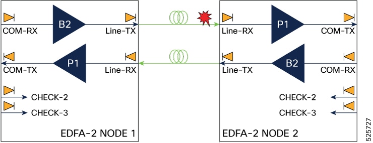
Optical safety on the BST2 amplifier in the Line-TX side, involves implementing the shutdown and automatic restart of the amplifier to prevent hazardous exposure to laser emissions.
BST2 amplifier shutdown process
The BST2 shutdown process outlines the step-by-step sequence of powering down the amplifiers.
-
Fiber is cut from Node1 to Node2.
-
In Node2, the Line-RX photodiode detects an LOS-P event. After 50 ms of soaking, the ALS mechanism shuts down the B2 amplifier in Node2.

Note
When a fiber cut occurs, both the communication channels and the OSC signal are lost, leading to an LOC alarm. However, if only the communication channels are lost and the OSC signal remains intact, an LOS-P) alarm is triggered.
-
This in turn causes a LOS-P event detected by the Node 1 Line-RX photodiode. After 50 ms of soaking, B1 in Node1 shuts down.
-
No power is present on the open fiber.
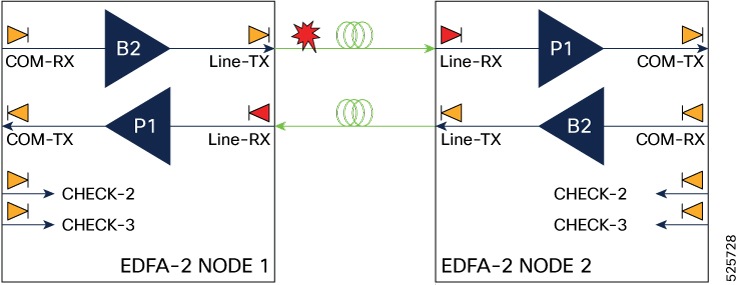
BST2 amplifier restart process
During amplifier restart, the system operates in pulse mode with Automatic Power Reduction (APR) activated. This ensures the Hazard Level 1 power limit is not exceeded while allowing safe system recovery.
-
At this point, the Line-TX port in Node 1 attempts to establish communication to Line-RX in Node 2 by emitting a pulse. The pulse cycle consists of 100 seconds with the laser off, followed by 5 to 15 seconds with the laser on at an output power of +8 dBm.
-
The Line-RX port in Node1 waits for a similar pulse in response from the Line-TX port of Node 2.
-
If no response is received within some seconds, the Node 1 tries again and again until it receives a response pulse from Line-TX port of Node2, indicating the system failure is corrected and full continuity in the fiber between the two ends exists.
-
The Node 1 amplifier operates in pulse mode at a reduced power level. It emits a laser pulse with an automatic power reduction to +20 dBm. This level assures that Hazard Level 1 is not exceeded, for personnel safety, even though the establishment of successful OSC communication is assurance that any broken fiber is fixed.
-
If Line-TX port of Node2 amplifier responds with a longer pulse within a particular duration, both amplifiers are changed from pulse mode at reduced power to normal operating power mode.
Optical safety on the PRE amplifier
PRE amplifier safety schema
In the context of PRE amplifier, the devices that receive its signal are demultiplexers. These are external components that require fiber connections. To ensure safety, they must be connected between the EDFA and the Demux monitor port. Therefore, the safety schema shown in these images is essential.There are two type of safety schema layouts:-
Double passive layout: Utilizes both passive modules, NCS1K-MD-32O-CE and NCS1K-MD-32E-CE.
Figure 3. EDFA2 with double passive layout 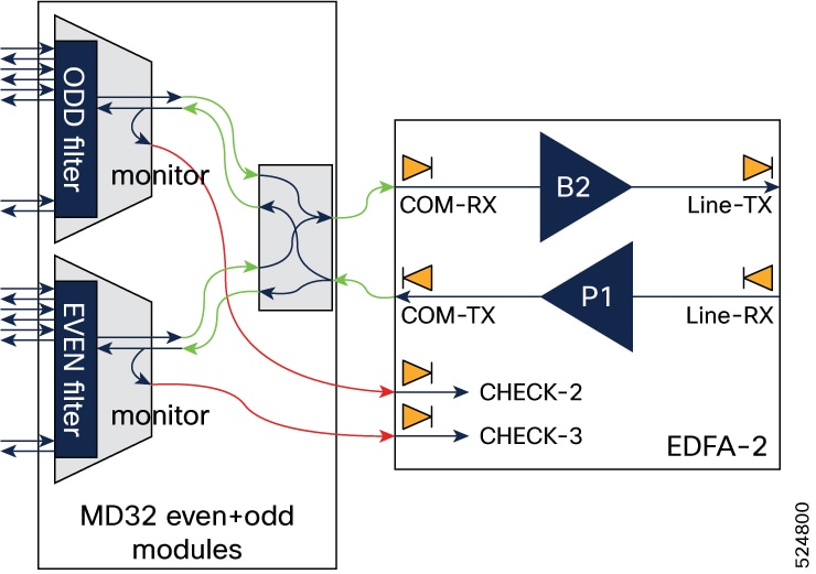
-
Single passive layout: Utilizes one of the passive modules
Figure 4. EDFA2 with single passive layout 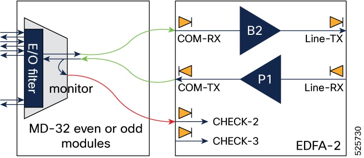
Safety schema implementation
To detect any open connection between the PRE amplifier output and the COM RX port on the passive module, connect the monitor ports on passive modules to the CHECK-RX ports of the EDFA2 card using cables indicated by red links.
-
Double passive module setup: When both NCS1K-MD-32O-CE and NCS1K-MD-32E-CE modules are present, connect loopbacks between their monitor ports using the two check ports.
-
Single Passive Module Setup: If only one module (either ODD or EVEN) is present, connect a single loopback to one check port and shut down the other port.
PRE amplifier shutdown behavior
Note |
Only the CHECK ports that are configured as In-Service (IS) participate in PRE amplifier safety operations. |
-
Double passive layout : Both ports must be configured as IS. The PRE amplifier shuts down only if one of the CHECK-2 and CHECK-3 ports detect power below the threshold.
-
Single passive layout: The EDFA2 CHECK2 port connected to the MD32 MON-E-DMX port must be configured as IS, while the other CHECK port should be Out of Service (OOS).
-
The PRE amplifier shuts down when the CHECK2 port in IS detects power below the threshold.
-
When both CHECK 2 and CHECK 3 ports are Out of Service (OOS), the PRE amplifier remains on, maintaining a power level of up to 20 dBm.
-
PRE amplifier restart procedure
To restart the PRE amplifier, create a loop connection between the Demux monitor port and one of the CHECK ports. After shutdown, the PRE amplifier can return to operation based on the loop connection evaluation to determine if one or both ports need to be alarm-free before restarting.
-
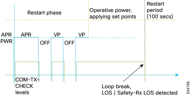
The PRE amplifier activates in APR mode with output power set to a safe level of 8 dBm.
-
The check starts with an 8-second APR pulse. If power is present on the CHECK port at the end, a Verification Phase (VP) begins:
-
Two off/on cycles are performed, monitoring expected alarm transitions.
-
Double passive layout : The alarm pattern must be detected on both CHECK2 and CHECK3 ports for PRE amplifier restart.
-
Single passive layout: The alarm pattern must be detected only on the CHECK port configured as IS.
-
-
Alarm transitions during cycles are verified to ensure proper responses. If transitions are not as expected, the process pauses, retrying after 100 seconds
-
The restart procedure is completely safe because PRE amplifier is operating at low power level (APR).
This picture demonstrates PRE amplifier power levels and alarm levels during a successful restart and subsequent shutdown event.
 Feedback