Channel APC
From Release 25.2.1, Channel APC is supported on the EDFA2 card. It is an optical application that maintains all optical channels at a consistent Power Spectral Density (PSD) target by dynamically regulating optical components. This ensures a flat spectrum before transmission over the fiber span.
The purpose of the Channel APC control loop is to equalize the Power Spectral Density (PSD) of all channels to a defined Channel Target PSD.
- Channel Target PSD:
This is an optical-line-control (OLC) configuration parameter that defines the desired PSD level for all channels. By default, this value is –20 dBm, measured in dBm/12.5GHz.
- Optical Channel Monitor (OCM):
The OCM device provides readings of the channel power spectral density, dividing the spectrum into 6.25GHz slices. The Channel PSD is calculated based on readings from the OCM and is averaged over the central 25GHz bandwidth.
- Input Channel Acceptance:
Before a channel is transmitted, its input PSD is evaluated against the Channel PSD target plus a defined margin (PSD_MARGIN). A channel is accepted and unblocked by the Wavelength Blocker (WB) if its estimated PSD after initial amplification and WB insertion loss is greater than the target PSD plus the margin.
- PSD Control Loop:
Once a channel is accepted, the WB attenuation for the channel's slices is adjusted from maximum to an initial value calculated to bring the Channel PSD near or slightly below the target. The control loop then periodically monitors the Channel PSD at the WB output. If the discrepancy between the measured PSD and the target PSD exceeds a defined threshold (PSD Correction Tolerance), the WB attenuation is corrected incrementally. The loop continues until the discrepancy is small, applying a final correction equal to the residual error. The loop regulates again if the discrepancy later exceeds the threshold.
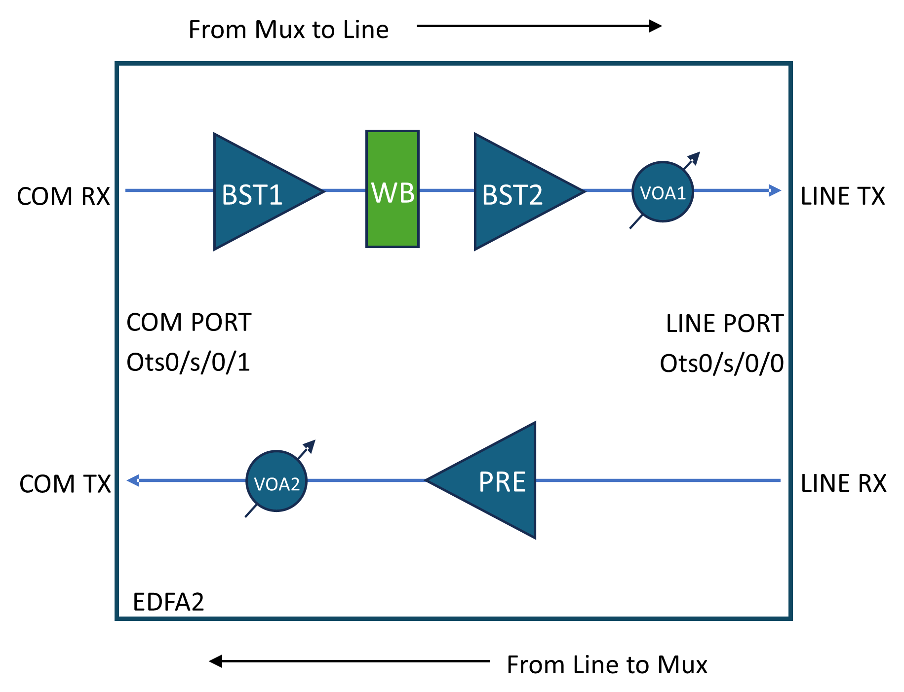
This diagram shows the NCS1K14-EDFA2 line card optical layout. Optical components controlled by channel APC are highlighted in green.
Channel Acceptance and Blocking Criteria
- Acceptance:
-
By default, WB blocks all C-band spectrum.
-
Channels must have PSD after WB (0 attenuation) higher than the target PSD plus a 0.5 dBm/12.5 GHz margin to be accepted.
-
- Blocking:
-
Channels with WB attenuation at 0 dB and PSD lower than target PSD minus 2.0 dBm/12.5 GHz tolerance are blocked by the control loop.
-

 Feedback