This topic explains the supported Cisco Optical Site Manager HA deployment models and the differences in connectivity, interface design, and failure behavior. It helps you compare options and select a model that matches site topology and operational requirements.
Cisco Optical Site Manager supports several deployment models for implementing high availability (HA), each with distinct configuration requirements, advantages, and dependencies on the Data Communication Network (DCN) architecture and local site availability. Each model:
analyzes possible deployment scenarios, detailing device connections and configurations,
covers routing protocols in use and information on any additional devices involved.
Cisco Optical Site Manager supports these deployment models:
Dual-homing deployment with devices connected to DCN: This model involves connecting devices to the DCN using a dual-homing setup.
Single-homing deployment with devices connected to DCN: This model utilizes a single-home connection for devices to the DCN.
Deployment with devices interconnected and managed remotely: In this model, devices are interconnected and managed remotely through the Optical Service Channel (OSC).
Deployment with devices interconnected with redundancy and managed remotely: This model extends the previous one by incorporating redundancy for devices interconnected and remotely managed via OSC.
Dual-homing deployment with devices connected to DCN
This deployment model ensures that Cisco Optical Site Manager can always communicate with its peer, routing traffic through an alternative interface, cable, or switch if one fails.
Requirements for the dual-homing deployment
This HA deployment model requires following conditions:
Both Cisco Optical Site Manager redundancy and management interfaces must be configured as Loopback interfaces.
The IP addresses assigned to the MgmtEth interfaces of the devices are typically part of a private subnet, isolated under the Top-of-Rack (ToR) switches.
Loopback IP addresses are distributed within the Data Communication Network (DCN) and must be reachable from Cisco Optical Network Controller.
Loopback 0 interfaces are designated as Cisco Optical Site Manager management interfaces.
Loopback 1 interfaces serve as Cisco Optical Site Manager redundancy interfaces, also providing direct access to the devices.
Implementing this deployment model requires specific network configurations and routing considerations:
ToR switches must advertise the default route to downstream devices. This can be achieved by configuring a static route on the devices or by using `default-information originate` with OSPF on the switches.
The two devices hosting Cisco Optical Site Manager in high availability must have a static route or routing protocol configuration to reach the peer's Cisco Optical Site Manager redundancy interface (for example, Loopback 1 interface) using the VRRP IP as the next hop.
ToR switches should implement VRRP and channel aggregation on multiple ports towards the peer switch for enhanced redundancy.
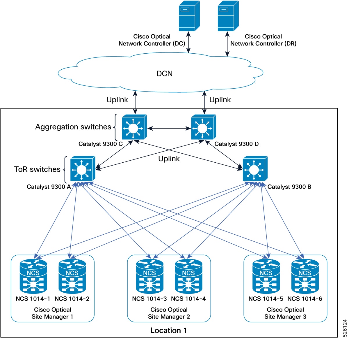
This figure explains the connections diagram of two-degrees node deployment model with devices connected to DCN in dual-homing.
Figure 1. Conceptual Explanation of High Availability Deployment for Devices Connected to DCN in a Dual-Homing Model
IP addressing schema for devices connected to DCN in dual-homing
This table details the IP addressing for the devices connected to DCN in dual-homing deployment model, with MgmtEth interfaces of the devices using the 192.168.1.0/24 subnet and loopback interfaces distributed within the DCN as part of the 10.1.1.0/27 subnet.
Table 1. IP addressing schema for dual-homing deployment
Cisco Optical Site Manager instance
NCS device
NCS device interface
NCS device IP/Mask
Connected to switch
Connected to switch interface
Cisco Optical Site Manager 1
NCS 1000-1
MgmtEth0/RP0/CPU0/0
192.168.1.11/24
Catalyst 9300 (A)
Gil/0/1
MgmtEth0/RP0/CPU0/1
192.168.1.12/24
Catalyst 9300 (B)
Gil/0/1
Loopback 0
10.1.1.1/32
–
–
Loopback 1
10.1.1.11/32
–
–
NCS 1000-2
MgmtEth0/RP0/CPU0/0
192.168.1.13/24
Catalyst 9300 (A)
Gil/0/2
MgmtEth0/RP0/CPU0/1
192.168.1.14/24
Catalyst 9300 (B)
Gil/0/2
Loopback 0
10.1.1.1/32
–
–
Loopback 1
10.1.1.12/32
–
–
Cisco Optical Site Manager 2
NCS 1000-3
MgmtEth0/RP0/CPU0/0
192.168.1.15/24
Catalyst 9300 (A)
Gil/0/3
MgmtEth0/RP0/CPU0/1
192.168.1.16/24
Catalyst 9300 (B)
Gil/0/3
Loopback 0
10.1.1.2/32
–
–
Loopback 1
10.1.1.13/32
–
–
NCS 1000-4
MgmtEth0/RP0/CPU0/0
192.168.1.17/24
Catalyst 9300 (A)
Gil/0/4
MgmtEth0/RP0/CPU0/1
192.168.1.18/24
Catalyst 9300 (B)
Gil/0/4
Loopback 0
10.1.1.2/32
–
–
Loopback 1
10.1.1.14/32
–
–
Cisco Optical Site Manager 3
NCS 1000-5
MgmtEth0/RP0/CPU0/0
192.168.1.19/24
Catalyst 9300 (A)
Gil/0/5
MgmtEth0/RP0/CPU0/1
192.168.1.20/24
Catalyst 9300 (B)
Gil/0/5
Loopback 0
10.1.1.3/32
–
–
Loopback 1
10.1.1.15/32
–
–
NCS 1000-6
MgmtEth0/RP0/CPU0/0
192.168.1.21/24
Catalyst 9300 (A)
Gil/0/6
MgmtEth0/RP0/CPU0/1
192.168.1.22/24
Catalyst 9300 (B)
Gil/0/6
Loopback 0
10.1.1.3/32
–
–
Loopback 1
10.1.1.16/32
–
–
Practical example of devices connected to DCN in dual-homing
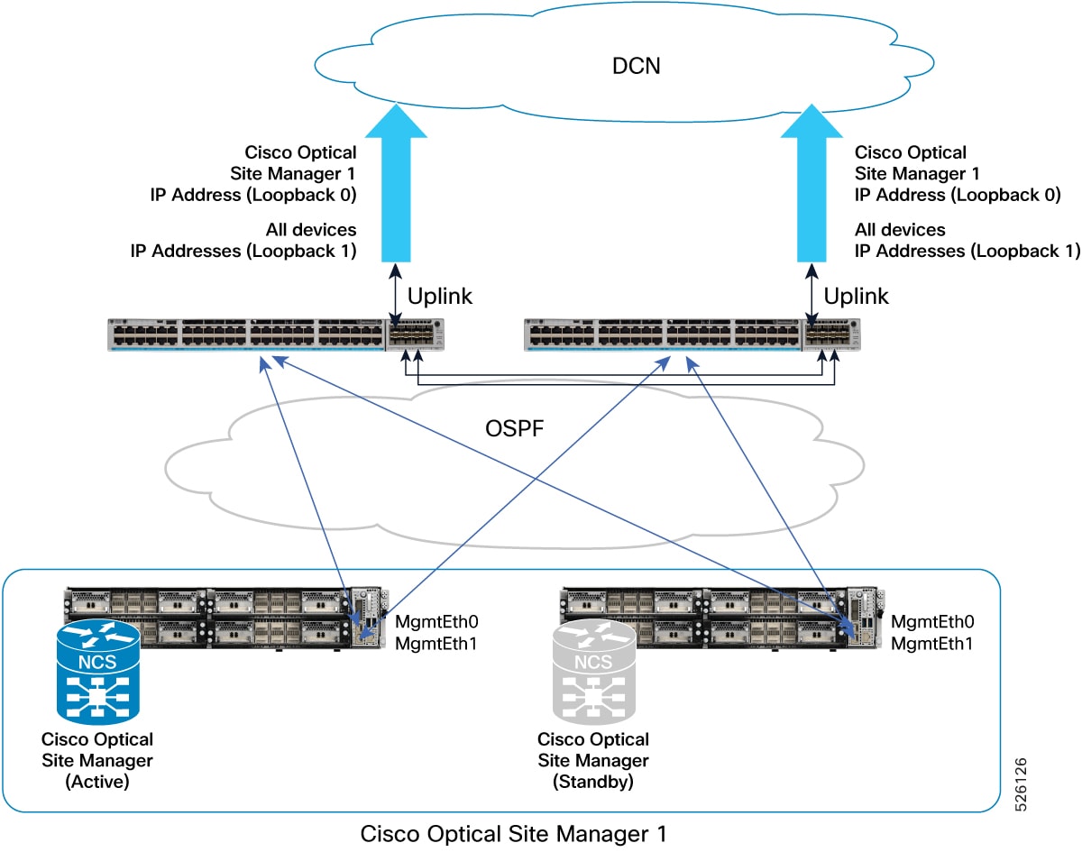
This figure provides a practical example of this deployment model, implemented with two Catalyst 9300 switches and two NCS1014 devices.
Figure 2. Deployment model featuring Catalyst 9300 Switches and Active/Standby NCS1014 devices
This example details the configurations for a Dual-Homing HA deployment model of NCS1014 devices connected to a DCN via Catalyst 9300 switches.
Catalyst 9300-A configuration
hostname CAT9300-A

fhrp version vrrp v3
ip routing

interface Vlan1
 ip address 192.168.1.253 255.255.255.0
 ip ospf 1 area 0
 vrrp 1 address-family ipv4
  address 192.168.1.1 primary
  exit-vrrp

interface TenGigabitEthernet1/1/1
 no switchport
 ip address <Uplink IP> <Uplink mask>

interface TenGigabitEthernet1/1/2
 channel-group 1 mode active

interface TenGigabitEthernet1/1/3
 channel-group 1 mode active

router ospf 1
 router-id 192.168.1.253
 default-information originate

ip route 0.0.0.0 0.0.0.0 <Uplink gateway IP>
Catalyst 9300-B configuration
hostname CAT9300-B

fhrp version vrrp v3
ip routing

interface Vlan1
 ip address 192.168.1.254 255.255.255.0
 ip ospf 1 area 0
 vrrp 1 address-family ipv4
  address 192.168.1.1 primary
  exit-vrrp

interface TenGigabitEthernet1/1/1
 no switchport
 ip address <Uplink IP> <Uplink mask>

interface TenGigabitEthernet1/1/2
 channel-group 1 mode active

interface TenGigabitEthernet1/1/3
 channel-group 1 mode active

router ospf 1
 router-id 192.168.1.254
 default-information originate

ip route 0.0.0.0 0.0.0.0 <Uplink gateway IP>
Single-homing deployment with devices connected to DCN
This deployment model for utilizes a single Top-of-Rack (ToR) switch and a single Management Ethernet interface for device connectivity.
Requirements for the single-homing deployment
This HA deployment model requires following conditions:
Devices connect to the network over a single MgmtEth interface with a single cable to a single ToR switch.
The Cisco Optical Site Manager redundancy interface can match the cabled interface (MgmtEth 0).
The Cisco Optical Site Manager management interface must be configured as a Loopback interface (Loopback 0).
IP addresses assigned to the MgmtEth interfaces can be part of a private subnet isolated under the ToR switches.
The Loopback IP address should be distributed within the Data Communication Network (DCN) and be reachable from CONC.
Direct access to the devices is always possible through the MgmtEth 0 IP addresses.
This deployment model offers specific operational characteristics and configuration guidelines:
While a single failure can impact the reachability of a device, Cisco Optical Site Manager configured in high availability remains continuously reachable.
The address plan and configurations described are specifically focused on the deployment of transponder platforms (e.g., NCS1014) to highlight differences from other deployment models.
For optical line system platforms (e.g., NCS1010) in a mesh network, where an alternative path to reach the Cisco Optical Site Manager peer device exists via OSC, the address plan and configurations are consistent with models using Loopback interfaces for both Cisco Optical Site Manager redundancy and management interfaces (excluding MgmtEth0/RP0/CPU0/1 configuration if not cabled).
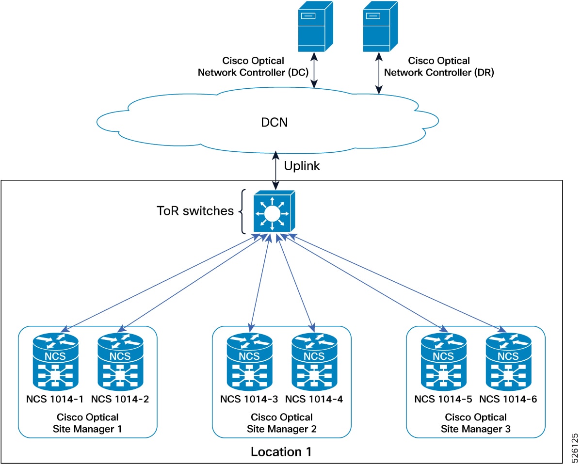
This figure explains the connections diagram of three Cisco Optical Site Manager instances configured in high availability mode on NCS 1000 device with devices connected to DCN in single-homing.
Figure 3. Conceptual explanation of HA deployment for devices connected to DCN in a single-homing model
IP addressing schema for devices connected to DCN in single-homing
This table details the IP addressing for the devices connected to DCN in single-homing deployment model, with the MgmtEth interface of the devices in subnet 192.168.1.0/24 and the Loopback interface distributed in the DCN as part of the subnet 10.1.1.0/27.
Table 2. IP addressing schema for single-homing deployment
Cisco Optical Site Manager instance
NCS device
NCS device interface
NCS device IP/Mask
Connected to switch
Connected to switch interface
Cisco Optical Site Manager-1
NCS 1000-1
MgmtEth0/RP0/CPU0/0
192.168.1.11/24
Catalyst 9300
Gi1/0/1
Loopback 0
10.1.1.1/32
–
–
NCS 1000-2
MgmtEth0/RP0/CPU0/0
192.168.1.12/24
Catalyst 9300
Gi1/0/2
Loopback 0
10.1.1.1/32
–
–
Cisco Optical Site Manager-2
NCS 1000-3
MgmtEth0/RP0/CPU0/0
192.168.1.13/24
Catalyst 9300
Gi1/0/3
Loopback 0
10.1.1.2/32
–
–
NCS 1000-4
MgmtEth0/RP0/CPU0/0
192.168.1.14/24
Catalyst 9300
Gi1/0/4
Loopback 0
10.1.1.2/32
–
–
Cisco Optical Site Manager-3
NCS 1000-5
MgmtEth0/RP0/CPU0/0
192.168.1.15/24
Catalyst 9300
Gi1/0/5
Loopback 0
10.1.1.3/32
–
–
NCS 1000-6
MgmtEth0/RP0/CPU0/0
192.168.1.16/24
Catalyst 9300
Gi1/0/6
Loopback 0
10.1.1.3/32
–
–
Practical example of devices connected to DCN in single-homing
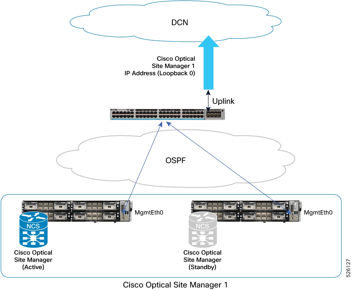
This figure provides a practical example of this deployment model, implemented with one Catalyst 9300 switch and two NCS 1014 devices.
Figure 4. Deployment model featuring Catalyst 9300 switch and Active/Standby NCS 1014 devices
This example details the configurations for a single-homing HA deployment model of NCS 1014 devices connected to a DCN via a Catalyst 9300 switch.
Catalyst 9300 configuration
hostname CAT9300

ip routing
interface Vlan1
 ip address 192.168.1.1 255.255.255.0
 ip ospf 1 area 0

interface TenGigabitEthernet1/1/1
 no switchport
 ip address <Uplink IP> <Uplink mask>

router ospf 1
 router-id 192.168.1.1
 default-information originate

ip route 0.0.0.0 0.0.0.0 <Uplink gateway IP>
Deployment with devices interconnected and managed remotely via OSC
This deployment model facilitates the management of a remote node, specifically a 2-degrees ROADM, where devices are interconnected without direct Data Communication Network (DCN) connectivity.
Requirements for devices interconnected and managed remotely via OSC
This HA deployment model requires these conditions:
Cisco Optical Site Manager is configured in high availability mode on the remote node.
The remote node is reachable over the Optical Service Channel (OSC) from other nodes connected to the customer's DCN.
Devices within the remote node (e.g., Location 2) achieve DCN reachability through multiple paths over the OSC of different degrees.
The two devices hosting Cisco Optical Site Manager in high availability are directly interconnected through an Ethernet cable connected to their MgmtEth interfaces.
Implementing this deployment model requires specific interface configurations and routing to ensure high availability and remote manageability, independent of failures.
Both Cisco Optical Site Manager redundancy and management interfaces must be configured as Loopback interfaces to ensure reachability independent of potential failures.
IP addresses assigned to the MgmtEth interfaces (used for device interconnection) and GigabitEthernet interfaces must be strategically distributed within the network to support interconnection failures.
Loopback IP addresses must be distributed within the DCN and be reachable from the Centralized Operations and Network Control (CONC) system.
The two devices hosting Cisco Optical Site Manager in high availability in the remote location, which are directly interconnected via an Ethernet cable on their MgmtEth interfaces, require a static route or routing protocol configuration.
This routing configuration must define how to reach the peer's Cisco Optical Site Manager redundancy interface (e.g., Loopback 1 interface) using the peer's MgmtEth interface as the next hop.
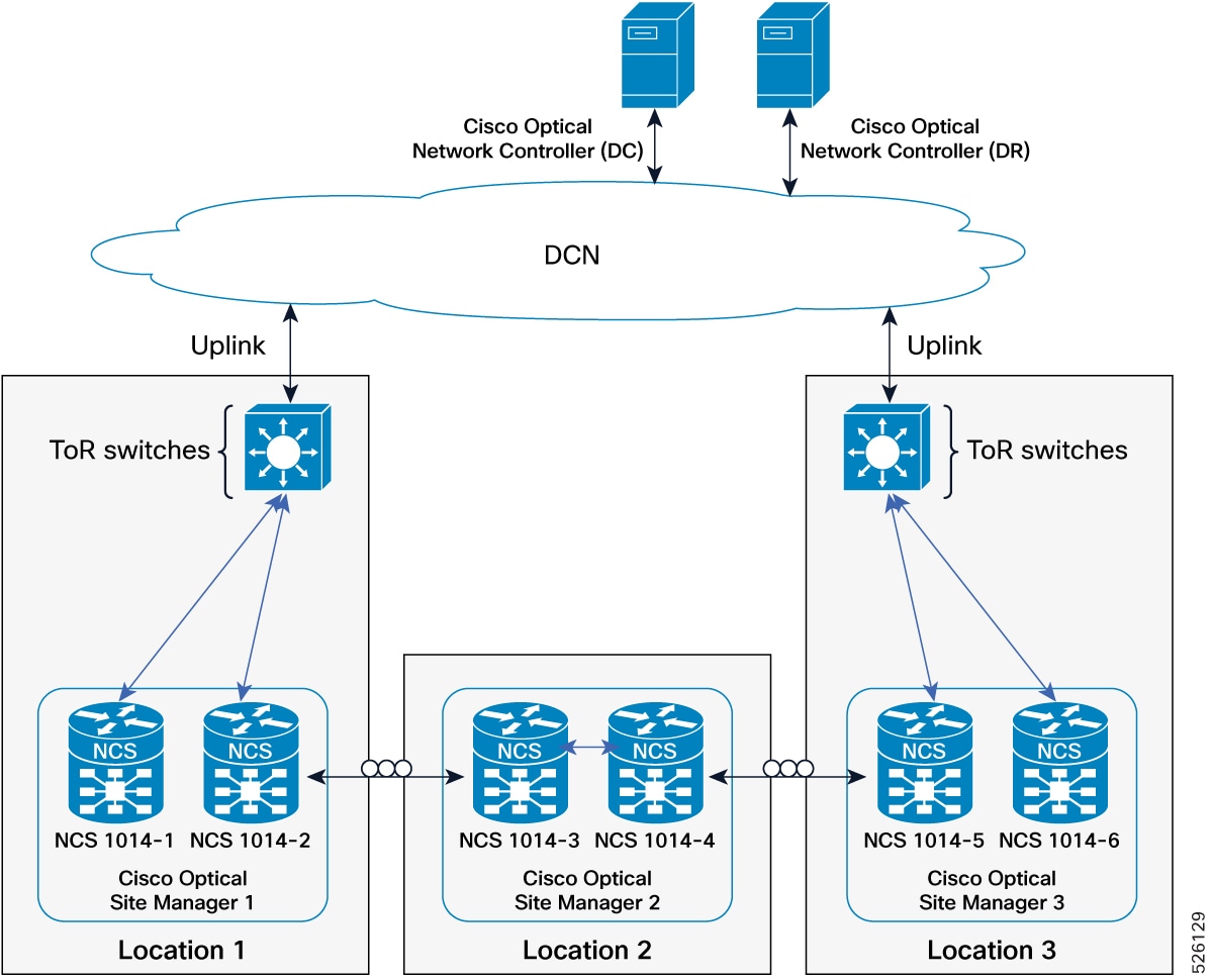
This figure shows a network diagram with three Cisco Optical Site Manager instances in three different locations, configured in HA mode on NCS 1000 family devices. The Cisco Optical Site Manager-2 device in the middle is managed as a remote device.
Figure 5. Conceptual explanation of HA deployment for devices interconnected and managed remotely via OSC
IP addressing schema for devices interconnected and managed remotely via OSC
This table details the IP addressing for devices in the managed remotely via OSC deployment model. The MgmtEth interfaces are in subnet 192.168.1.12/31, and the Loopback interfaces are distributed in the DCN as part of subnet 10.1.1.0/27.
Table 3. IP addressing schema for deployment with devices interconnected and managed remotely
Cisco Optical Site Manager instance
NCS device
NCS device interface
NCS device IP/Mask
Connected to NCS device
Connected to NCS device interface
Cisco Optical Site Manager 2
NCS 1010-3
MgmtEth0/RP0/CPU0/1
192.168.1.12/31
Peer NCS 1010
MgmtEth0/RP0/CPU0/1
GigabitEthernet0/0/0/0
172.18.0.1/31
Neighbor
GigabitEthernet0/0/0/0
Loopback 0
10.1.1.2/32
–
–
Loopback 1
10.1.1.13/32
–
–
NCS 1010-4
MgmtEth0/RP0/CPU0/1
192.168.1.13/31
Peer NCS 1010
MgmtEth0/RP0/CPU0/1
GigabitEthernet0/0/0/0
172.18.0.2/31
Neighbor
GigabitEthernet0/0/0/0
Loopback 0
10.1.1.2/32
–
–
Loopback 1
10.1.1.14/32
–
–
Practical example of deployment with devices interconnected managed remotely via OSC
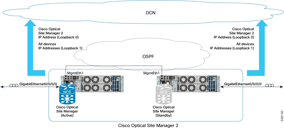
This figure provides a practical example of this deployment model, implemented with two NCS 1010 devices.
Figure 6. Example of deployment model with two NCS 1010 and Catalyst 93000 configured as 2-degrees ROADM
This example describes the configuration of two NCS 1010 devices deployed as a 2-degree ROADM, interconnected and managed remotely through the OSC.
Deployment with devices interconnected with redundancy and managed remotely via OSC
This deployment model describes the management of a remote node, a 2-degrees ROADM, with physical redundancy, where Cisco Optical Site Manager is configured in high availability and reachable over the Optical Service Channel.
Requirements for devices interconnected with redundancy and managed remotely via OSC
This HA deployment model requires these conditions:
Devices in the remote node are interconnected with physical redundancy and lack direct DCN connectivity.
Cisco Optical Site Manager instances are configured in high availability, accessible via OSC from other nodes connected to the customer's DCN.
Devices within the remote node (Location 2) achieve DCN reachability through multiple paths over the OSC with varying degrees.
Two devices hosting Cisco Optical Site Manager in high availability are directly interconnected through both an Ethernet cable plugged into MgmtEth interfaces and an external switch.
Implementing this deployment model requires specific interface configurations and routing to ensure high availability and remote manageability, even with physical redundancy.
Both Cisco Optical Site Manager redundancy and management interfaces must be configured as Loopback interfaces to ensure reachability independent of potential failures.
IP addresses assigned to the MgmtEth interfaces (used for device interconnection) and GigabitEthernet interfaces must be strategically distributed within the network to support interconnection failures.
Loopback IP addresses must be distributed within the DCN and be reachable from the Centralized Operations and Network Control (CONC) system.
The two devices hosting Cisco Optical Site Manager in high availability in the remote location require a static route or routing protocol configuration.
This routing configuration must define how to reach the redundancy interface for Cisco Optical Site Manager on the peer device (e.g., Loopback 1 interface) using the peer's MgmtEth interface as the next hop.
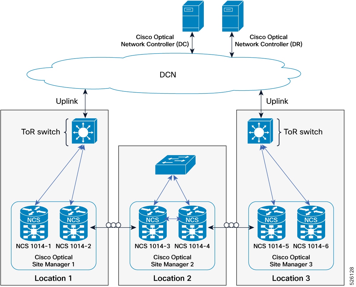
This figure illustrates the connection diagram of three Cisco Optical Site Manager instances in three different locations, configured in HA mode on NCS 1000 family devices. The device in the middle, Cisco Optical Site Manager-2, is managed as a remote device.
Figure 7. Conceptual explanation of deployment with devices interconnected with redundancy and managed remotely via OSC deployment
IP addressing schema for devices interconnected with redundancy and managed remotely via OSC deployment
This table details the IP addressing for the devices interconnected with redundancy and managed remotely via OSC deployment model, with the MgmtEth interfaces of the devices in subnets 192.168.1.0/24 and 192.168.2.12/31 and the Loopback interfaces distributed in the DCN as part of the subnet 10.1.1.0/27.
Table 4. IP addressing schema for devices interconnected with redundancy and managed remotely via OSC deployment
Cisco Optical Site Manager instance
NCS device
NCS device interface
NCS device IP/Mask
Connected to switch
Connected to switch interface
Cisco Optical Site Manager 2
NCS 1010-3
MgmtEth0/RP0/CPU0/0
192.168.1.12/24
Ext Switch
–
MgmtEth0/RP0/CPU0/1
192.168.2.12/31
Peer NCS1K
MgmtEth0/RP0/CPU0/1
GigabitEthernet0/0/0/0
172.18.0.1/31
Neighbor NCS1K
GigabitEthernet0/0/0/0
Loopback 0
10.1.1.2/32
–
–
Loopback 1
10.1.1.13/32
–
–
NCS 1010-4
MgmtEth0/RP0/CPU0/0
192.168.1.13/24
Ext Switch
–
MgmtEth0/RP0/CPU0/1
192.168.2.13/31
Peer NCS1K
MgmtEth0/RP0/CPU0/1
GigabitEthernet0/0/0/0
172.18.0.2/31
Neighbor NCS1K
GigabitEthernet0/0/0/0
Loopback 0
10.1.1.2/32
–
–
Loopback 1
10.1.1.14/32
–
–
Practical example of devices interconnected with redundancy and managed remotely via OSC deployment
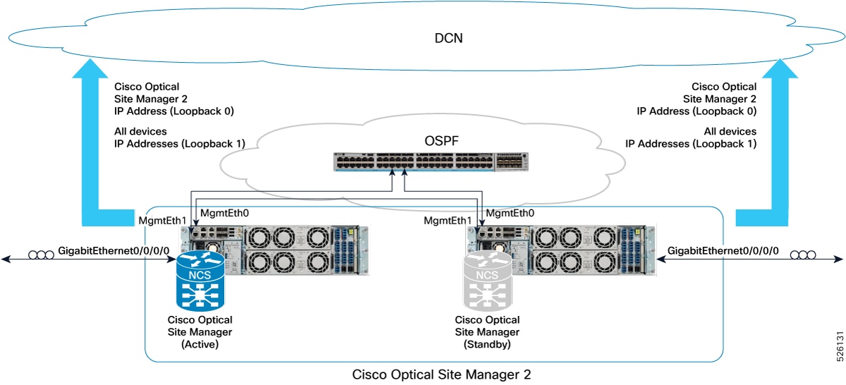
This figure provides a practical example of this deployment model, implemented with one Catalyst 9300 switch and two NCS 1010 devices.
Figure 8. Example of deployment model with two NCS 1010 configured as 2-degrees ROADM
Example configuration for the deployment
This example describes the configuration of two NCS 1010 devices set up as a 2-degree ROADM with redundancy and remote management through the OSC.